Tesla S 2012 User manual

EMERGENCY RESPONSE
GUIDE
This guide is intended only for use by trained and certified rescuers and first responders. It assumes that readers have a comprehensive understanding of how
safety systems work and have completed the appropriate training and certification required to safely handle rescue situations. Therefore, this guide provides only
the specific information required to understand and safely handle the fully electric Model S in an emergency situation. It describes how to identify ModelS, and
provides the locations and descriptions of its high voltage components, airbags, inflation cylinders, seat belt pre-tensioners, and high strength materials used in
its body structure. This guide includes the high voltage disabling procedure and any safety considerations specific to Model S. Failure to follow recommended
practices or procedures can result in serious injury or death.
The high voltage battery is the main energy source. Model S does not have a traditional gasoline or diesel engine and therefore does not have a fuel tank.
2012 - 2013

TABLE OF CONTENTS
P/N: SC-15-94-001
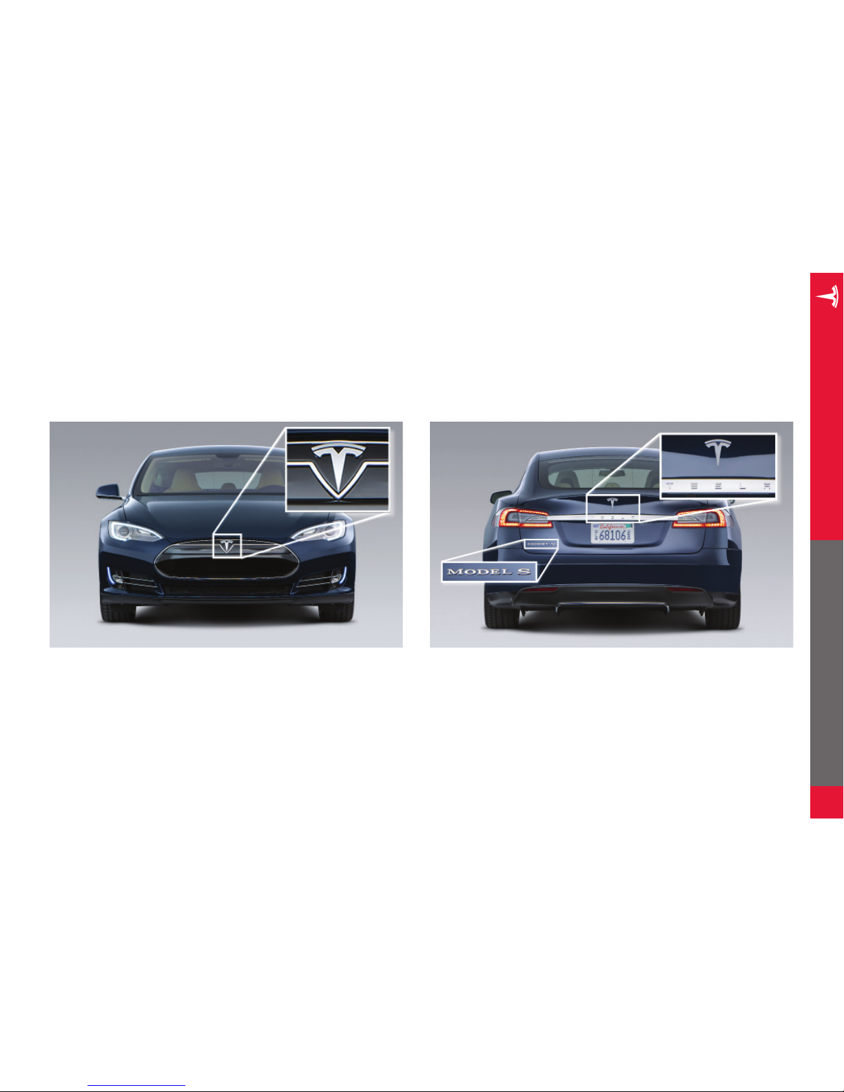
IDENTIFYING MODEL S...................................................................................1
BADGING.....................................................................................................................................1
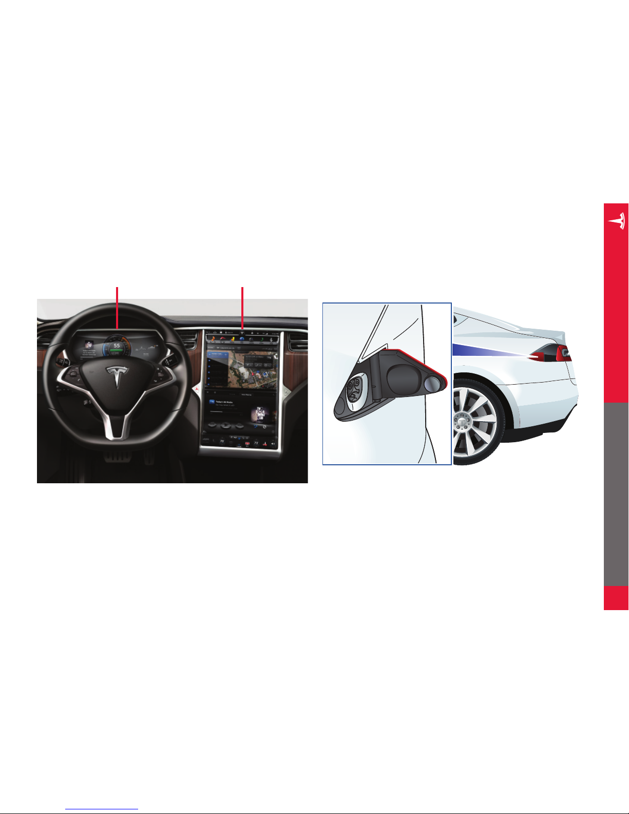
LARGE SCREEN..................................................................................................................... 2
CHARGE PORT....................................................................................................................... 2
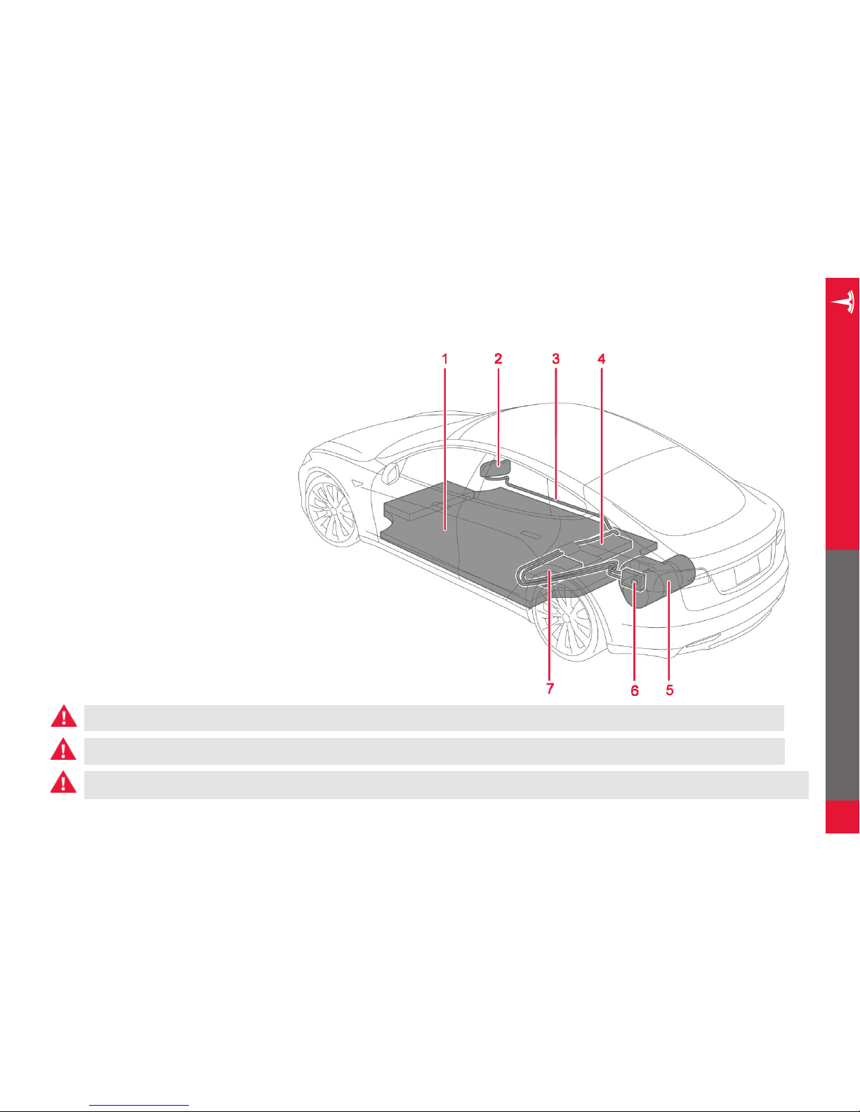
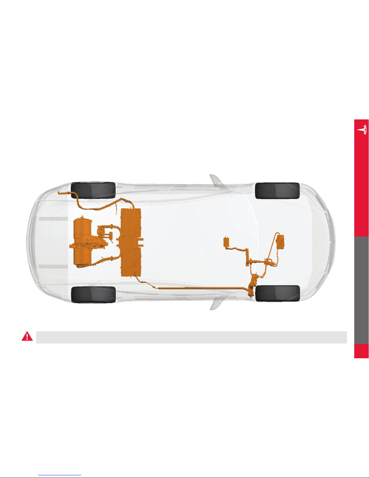
HIGH VOLTAGE COMPONENTS ..................................................................3
OVERVIEW OF HIGH VOLTAGE COMPONENTS................................................... 3
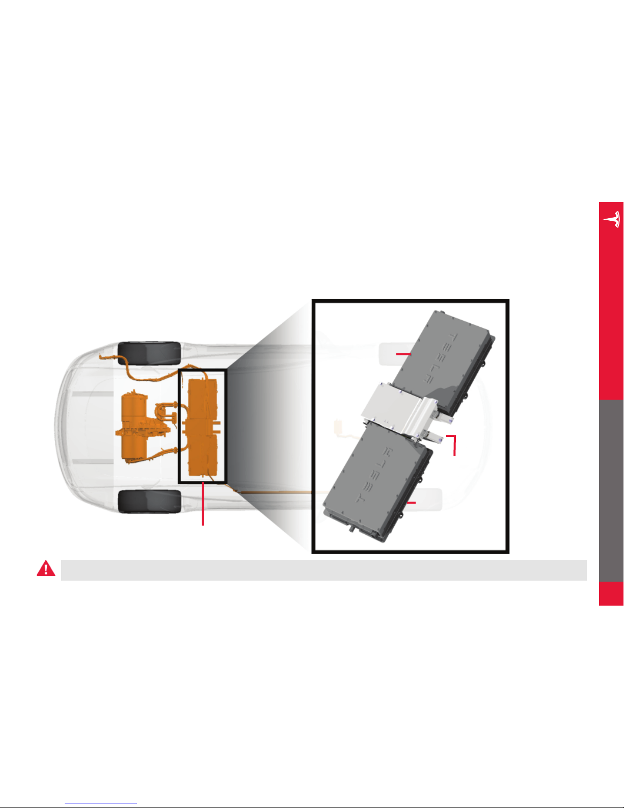
HIGH VOLTAGE BATTERY................................................................................................ 4
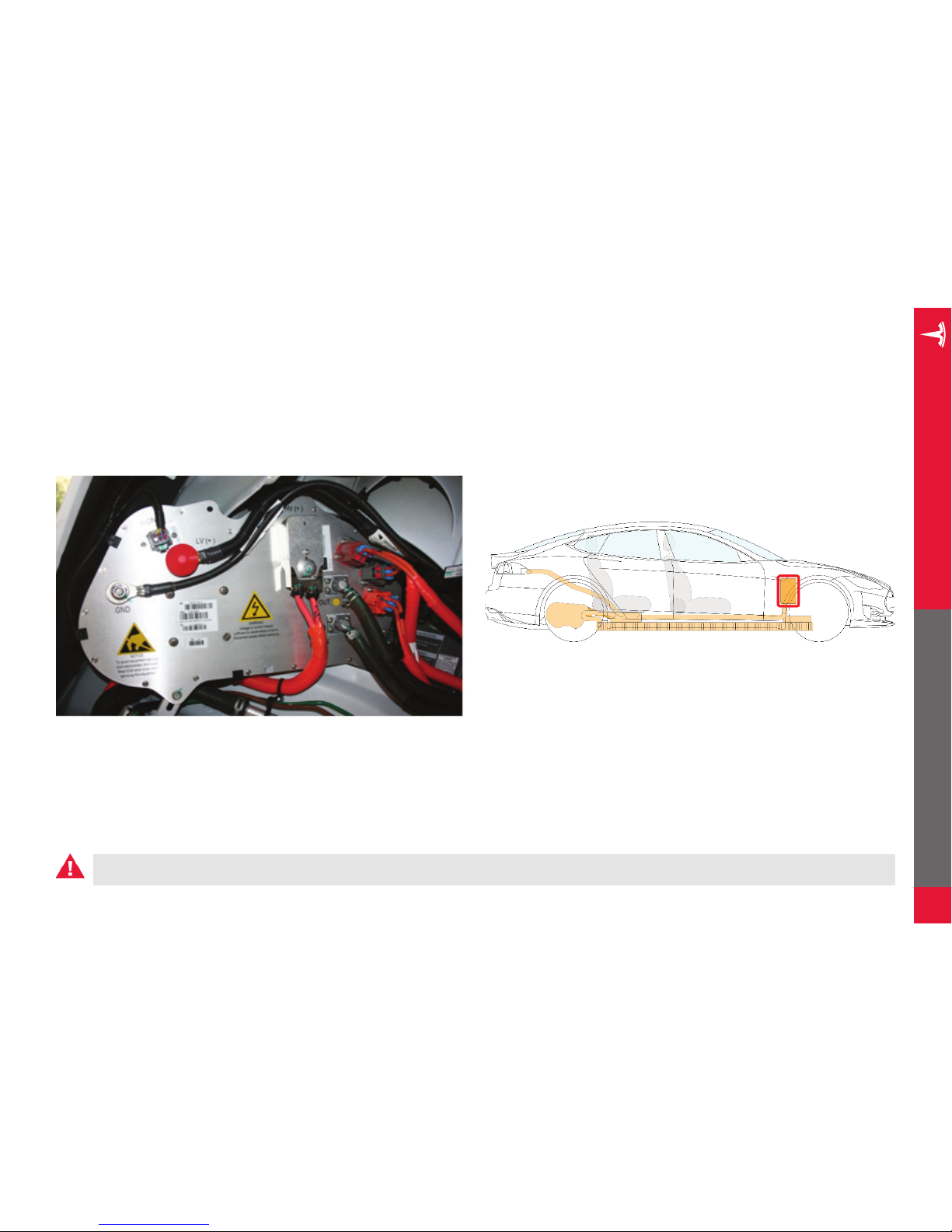
DC-DC CONVERTER ........................................................................................................... 5
HIGH VOLTAGE CABLING................................................................................................. 6
CHARGERS................................................................................................................................7
DRIVE UNIT.............................................................................................................................. 8
LOW VOLTAGE SYSTEM ................................................................................9
12V BATTERY........................................................................................................................... 9
DISABLING HIGH VOLTAGE........................................................................10
FIRST RESPONDER CUT LOOP - FRONT TRUNK ..............................................10
CUTTING THE FIRST RESPONDER LOOP - FRONT TRUNK .......................... 11
FIRST RESPONDER DISCONNECT POINT - REAR PILLAR (NEWER
MODELS ONLY) ....................................................................................................................12
CUTTING THE FIRST RESPONDER DISCONNECT POINT - REAR PILLAR
(NEWER MODELS ONLY)................................................................................................13
STABILIZING MODEL S................................................................................. 14
AIRBAGS AND SUPPLEMENTARY RESTRAINT SYSTEM (SRS)
..... 15
AIRBAGS...................................................................................................................................15
AIRBAG INFLATION CYLINDERS.................................................................................15
SEAT BELT PRE-TENSIONERS ......................................................................................16
REINFORCEMENTS........................................................................................ 17
NO-CUT ZONES............................................................................................... 18
RESCUE OPERATIONS ................................................................................. 19
FULLY OR PARTIALLY SUBMERGED VEHICLES .................................................19
PUSHING ON THE FLOOR PAN....................................................................................19
FIREFIGHTING ..................................................................................................................... 20
HIGH VOLTAGE BATTERY - FIRE DAMAGE ......................................................... 20
LIFTING MODEL S .......................................................................................... 21
OPENING MODEL S ...................................................................................... 22
USING THE KEY...................................................................................................................22
OPENING DOORS...............................................................................................................22
OPENING REAR DOORS WITH NO POWER.........................................................22
OPENING THE TRUNK......................................................................................................23
OPENING THE HOOD (FRONT TRUNK) .................................................................23
HIGH VOLTAGE LABELS ............................................................................. 24
INDEX ................................................................................................................. 25

EMERGENCY RESPONSE GUIDE
1
BADGING
Model S has three main badges to distinguish it.
IDENTIFYING MODEL S
IDENTIFYING MODEL S

EMERGENCY RESPONSE GUIDE
2
IDENTIFYING MODEL S
LARGE SCREEN
Model S has a large 17” touchscreen.
Instrument panel Touchscreen
CHARGE PORT
Model S has a charge port that is integrated into the taillight on
the rear left side fender.

EMERGENCY RESPONSE GUIDE
3
OVERVIEW OF HIGH VOLTAGE COMPONENTS
1. Battery
2. DC-DC converter
3. High voltage cabling (colored orange)
4. 10 kW on-board master charger
5. Drive unit
6. Charge port
7. OPTIONAL: 10 kW on-board slave
charger
WARNING: Regardless of the disabling procedure you use, ALWAYS ASSUME THAT ALL HIGH VOLTAGE COMPONENTS ARE ENERGIZED! Cutting, crushing or touching
high voltage components can result in serious injury or death.
HIGH VOLTAGE COMPONENTS
WARNING: The SRS control unit has a backup power supply with a discharge time of approximately ten seconds.
WARNING: After deactivation, the high voltage circuit requires two minutes to deplete.

EMERGENCY RESPONSE GUIDE
4
HIGH VOLTAGE BATTERY
Model S is equipped with a floor-mounted 400 volt lithium-ion high voltage battery. Never breach the high voltage battery when lifting
from under the vehicle. When using rescue tools, also pay special attention to ensure that you do not breach the floor pan.
HIGH VOLTAGE COMPONENTS
High voltage battery is located below the floor
WARNING: Regardless of the disabling procedure you use, ALWAYS ASSUME THAT ALL HIGH VOLTAGE COMPONENTS ARE ENERGIZED! Cutting, crushing or touching
high voltage components can result in serious injury or death.

EMERGENCY RESPONSE GUIDE
5
DC-DC CONVERTER
The DC-DC converter is located in the front right wheel well, on the right side of the firewall. It transforms the high voltage current from
the 400 volt battery to low voltage to charge the Model S 12 volt battery. High voltage is present at the DC-DC converter. Use caution
when cutting in this area during a dash lift (dash roll) procedure—use work-around techniques, if necessary.
HIGH VOLTAGE COMPONENTS
DC-DC converter is located on the
right side, towards the front
WARNING: Regardless of the disabling procedure you use, ALWAYS ASSUME THAT ALL HIGH VOLTAGE COMPONENTS ARE ENERGIZED! Cutting, crushing or touching
high voltage components can result in serious injury or death.

EMERGENCY RESPONSE GUIDE
6
HIGH VOLTAGE CABLING
High voltage cabling is highlighted in dark orange in the following illustration.
High voltage cabling is routed under the rear seats and inside the rocker panel on the right side front
HIGH VOLTAGE COMPONENTS
WARNING: Regardless of the disabling procedure you use, ALWAYS ASSUME THAT ALL HIGH VOLTAGE COMPONENTS ARE ENERGIZED! Cutting, crushing or touching
high voltage components can result in serious injury or death.

EMERGENCY RESPONSE GUIDE
7
CHARGERS
Model S has one (standard) or two (optional) chargers under the rear seat. These chargers convert the AC current from a charging
station to DC for charging the high voltage battery. A High Voltage Junction Box, located between the chargers, routes any surplus
energy from regenerative braking back to the battery.
Charger(s) are located under the
rear seat
HIGH VOLTAGE COMPONENTS
Master charger
(under rear right
side seat)
OPTIONAL:
Slave charger (under
rear left side seat)
High Voltage
Junction Box
WARNING: Regardless of the disabling procedure you use, ALWAYS ASSUME THAT ALL HIGH VOLTAGE COMPONENTS ARE ENERGIZED! Cutting, crushing or touching
high voltage components can result in serious injury or death.

EMERGENCY RESPONSE GUIDE
8
DRIVE UNIT
The drive unit is located between the rear wheels under the floor pan of the Model S. It converts the DC current from the high voltage
battery into the 3-phase AC current that the electric motor uses to power the wheels.
Drive unit is located between the rear wheels
HIGH VOLTAGE COMPONENTS
WARNING: Regardless of the disabling procedure you use, ALWAYS ASSUME THAT ALL HIGH VOLTAGE COMPONENTS ARE ENERGIZED! Cutting, crushing or touching
high voltage components can result in serious injury or death.

EMERGENCY RESPONSE GUIDE
9
12V BATTERY
In addition to the high voltage system, Model S has a low voltage system, powered by a traditional 12 volt battery. The low voltage
system operates the same electrical components found in conventional vehicles, including the supplementary restraint system (SRS),
airbags, ignition, touchscreen, and interior and exterior lights.
The low voltage system interacts with the high voltage system. The DC-DC converter supplies the 12V battery with power to support
low voltage functions, and the 12V battery supplies power to the high voltage contacts to allow power to flow out of the high voltage
battery.
12V battery is located on the right side,
under the hood and the plastic access panel
LOW VOLTAGE SYSTEM
LOW VOLTAGE SYSTEM
WARNING: Regardless of the disabling procedure you use, ALWAYS ASSUME THAT ALL HIGH VOLTAGE COMPONENTS ARE ENERGIZED! Cutting, crushing or touching
high voltage components can result in serious injury or death.

EMERGENCY RESPONSE GUIDE
10
FIRST RESPONDER CUT LOOP - FRONT TRUNK
The front trunk first responder cut loop consists of low voltage wires. Cutting this loop shuts down the high voltage system and disables
the SRS and airbag components. See cut instructions on page 11.
NOTE: When cutting the loop, double cut to remove an entire section. This eliminates the risk of the cut wires accidentally reconnecting.
The front trunk cut loop is located on the right side,
under the hood and the plastic access panel
FIRST RESPONDER CUT LOOP
DISABLING HIGH VOLTAGE
WARNING: Regardless of the disabling procedure you use, ALWAYS ASSUME THAT ALL HIGH VOLTAGE COMPONENTS ARE ENERGIZED! Cutting, crushing or touching
high voltage components can result in serious injury or death.
NOTE: If the front trunk cut loop is inaccessible in
vehicles built after June 2013, see pages 12-13 for
an alternate disconnect point.

EMERGENCY RESPONSE GUIDE
11
STEP 1: Open the hood (also known as the Front Trunk). See
page 23 for details.
The cut loop is located on the right side. Its label
protrudes from under the plastic access panel.
Cut loop
label
Remove
access
panel
DISABLING HIGH VOLTAGE
STEP 2: Remove the access panel by pulling its rear edge upward
to release the five clips that hold it in place. Maneuver it
toward the windshield to remove.
Double
cut the
loop
STEP 3: DOUBLE CUT the loop to remove an entire section.
Removing an entire section of the cut loop eliminates the
risk of the wires accidentally touching (reconnecting).
WARNING: Regardless of the disabling procedure you use, ALWAYS ASSUME THAT ALL HIGH VOLTAGE COMPONENTS ARE ENERGIZED! Cutting, crushing or touching
high voltage components can result in serious injury or death.
CUTTING THE FIRST RESPONDER LOOP - FRONT TRUNK

EMERGENCY RESPONSE GUIDE
12
FIRST RESPONDER DISCONNECT POINT - REAR PILLAR (NEWER MODELS ONLY)
If the front trunk cut loop is inaccessible on vehicles built after June 2013, the rear pillar disconnect point can shut down the high
voltage system and disable the SRS and airbag components in the same manner as the front trunk cut loop. See cut instructions on
page 13.
NOTE: Only one point needs to be disconnected, not both.
FIRST RESPONDER CUT LOOP
DISABLING HIGH VOLTAGE
WARNING: Regardless of the disabling procedure you use, ALWAYS ASSUME THAT ALL HIGH VOLTAGE COMPONENTS ARE ENERGIZED! Cutting, crushing or touching
high voltage components can result in serious injury or death.

EMERGENCY RESPONSE GUIDE
13
STEP 1: Open the rear passenger door closest to the charge port.
The disconnect point is located under the body panel on
the outside of the seat. The label indicates where to cut
into the body panel.
Cut loop
label
DISABLING HIGH VOLTAGE
STEP 2: Use a 12” circular saw to cut 6 in (152 mm) through the
label and into the pillar.
WARNING: Regardless of the disabling procedure you use, ALWAYS ASSUME THAT ALL HIGH VOLTAGE COMPONENTS ARE ENERGIZED! Cutting, crushing or touching
high voltage components can result in serious injury or death.
CUTTING THE FIRST RESPONDER DISCONNECT POINT - REAR PILLAR (NEWER
MODELS ONLY)

EMERGENCY RESPONSE GUIDE
14
STABILIZING MODEL S
CHOCK ALL FOUR WHEELS
Drivers can choose a setting that determines whether or not
Model S will “creep” when a driving gear is selected. If this setting
is o, Model S does not move unless the accelerator is pressed,
even if shifted into Drive or Reverse. However, never assume that
Model S will not move. Always chock the wheels.
STABILIZING MODEL S
STABILIZING MODEL S
SHIFT INTO PARK
Model S is silent so never assume it is powered o. Pressing the
accelerator pedal even slightly can cause Model S to move quickly
if the currently active gear is Drive or Reverse. To ensure that
the parking brake is engaged, press the button on the end of the
gear selector to shift into Park. Whenever Model S is in Park, the
parking brake is automatically engaged so that the vehicle will not
move if the accelerator pedal is pressed.
WARNING: Regardless of the disabling procedure you use, ALWAYS ASSUME THAT ALL HIGH VOLTAGE COMPONENTS ARE ENERGIZED! Cutting, crushing or touching
high voltage components can result in serious injury or death.

EMERGENCY RESPONSE GUIDE
15
AIRBAGS
Model S is equipped with eight airbags. Responders should de-
energize the airbags by cutting the First Responder Cut Loop (see
page 11) or Disconnect Point (see page 13). Airbags are shown
below in blue.
AIRBAG INFLATION CYLINDERS
Airbag (stored gas) inflation cylinders are located toward the rear
of the vehicle, as shown below in red.
AIRBAGS AND SRS
AIRBAGS AND SRS
Airbag inflation cylinders
are located toward the rear
WARNING: Regardless of the disabling procedure you use, ALWAYS ASSUME THAT ALL HIGH VOLTAGE COMPONENTS ARE ENERGIZED! Cutting, crushing or touching
high voltage components can result in serious injury or death.

EMERGENCY RESPONSE GUIDE
16
SEAT BELT PRE-TENSIONERS
Seat belt pre-tensioners are located by the B-pillars, as shown below in red.
AIRBAGS AND SRS
Seat belt pre-tensioners are located by the B-pillars
WARNING: Regardless of the disabling procedure you use, ALWAYS ASSUME THAT ALL HIGH VOLTAGE COMPONENTS ARE ENERGIZED! Cutting, crushing or touching
high voltage components can result in serious injury or death.

EMERGENCY RESPONSE GUIDE
17
LOCATION OF REINFORCEMENTS AND HIGH STRENGTH STEEL
Model S is reinforced to protect occupants in a collision. Reinforcements are shown below in green (high strength steel) and blue (extruded
aluminum).
Depending on the tools used, high strength steel can be challenging or impossible to cut. If necessary, use workaround techniques.
REINFORCEMENTS
HIGH STENGTH STEEL
Only the side B-pillars are reinforced
with high strength steel
The side doors and roof support are
reinforced with extruded aluminum
WARNING: Regardless of the disabling procedure you use, ALWAYS ASSUME THAT ALL HIGH VOLTAGE COMPONENTS ARE ENERGIZED! Cutting, crushing or touching
high voltage components can result in serious injury or death.
WARNING: Always use appropriate tools (such as a hydraulic cutter), and always wear appropriate personal protective equipment (PPE) when cutting Model S. Failure to
follow these instructions can result in serious injury or death.
Extruded
aluminum
Extruded
aluminum
High strength
steel
High strength
steel
High strength
steel
Extruded
aluminum

EMERGENCY RESPONSE GUIDE
18
NO-CUT ZONES
Model S has areas that are defined as “no-cut zones” due to high voltage, gas struts, and SRS or airbag hazards. Never cut or crush
these areas—doing so can result in serious injury or death.
NO CUT ZONES
NO-CUT ZONES
Do not cut through areas shown in red
WARNING: Regardless of the disabling procedure you use, ALWAYS ASSUME THAT ALL HIGH VOLTAGE COMPONENTS ARE ENERGIZED! Cutting, crushing or touching
high voltage components can result in serious injury or death.
WARNING: Always use appropriate tools (such as a hydraulic cutter), and always wear appropriate personal protective equipment (PPE) when cutting Model S. Failure to
follow these instructions can result in serious injury or death.
Other manuals for S 2012
2
This manual suits for next models
1
Table of contents
Other Tesla Automobile manuals

Tesla
Tesla S 2017 User manual

Tesla
Tesla Model 3 User manual

Tesla
Tesla Y 2019 User manual

Tesla
Tesla MODEL Y 2012 User manual

Tesla
Tesla MODEL Y 2012 User manual

Tesla
Tesla 2010 Roadster User manual

Tesla
Tesla MODEL X 2019 User manual

Tesla
Tesla X 2016 User manual

Tesla
Tesla MODEL S User manual

Tesla
Tesla X User manual

Tesla
Tesla MODEL X 2015 User manual

Tesla
Tesla MODEL S Service manual

Tesla
Tesla MODEL 3 2020 User manual

Tesla
Tesla S 2014 User manual

Tesla
Tesla Feature 3 User manual

Tesla
Tesla MODEL S User manual

Tesla
Tesla Y 2020 User manual

Tesla
Tesla MODEL S User manual

Tesla
Tesla MODEL S User manual

Tesla
Tesla MODEL S User manual