Tesla 3 2018 User manual

2018-2019 Tesla Models:
3 / S / X
Roadside Service Guide
Quality and Education Services
AAA Automotive
April 10, 2019
For the latest updates from AAA, visit:
AAAcampus.aaa.biz

Index
Specications 3
Start/Stop Switch 4
Electronic Key/Mechanical Key 4
Electronic Key Not Detected 4
Trunk Lid Release 5
Hood Release 5
Car Carrier Loading 6
Front Towing Eyebolt 7
Electronic Parking Brake 8
Tires and Jacking 9
High-voltage System 10
Jump-Start Procedures 11
Important Notice:
This publication should not be used while driving. The procedures in this publication should only be
used by qualied and trained personnel.
ThisRoadsideServiceQuickReferenceGuidewasdevelopedtohighlightsomemodel-specicinformation
and common procedures for servicing or towing this vehicle. It is not all-inclusive. For complete informa-
tion: The applicable vehicle’s owner’s manual and the AAA/CAA Towing and Service Manual should be
used in conjunction with this guide.
Theproceduresrecommendedanddescribedinthisguideareeectivemethodsofperforminglightservice
and towing operations. Some of these procedures require the use of auxiliary equipment specially designed
for the purpose. The auxiliary equipment should be used as recommended and whenever the trained
operator deems it appropriate. It is important to read the various WARNINGS, CAUTIONS and NOTES
in this manual in order to minimize the risk of personal injury to service personnel and or customers and to
avoid procedures which may damage the vehicle or render it unsafe. It is also important to understand that
these warnings, cautions and notes are not exhaustive. Neither AAA nor the auto and towing equipment
manufacturers could possibly know, evaluate and advise the reader of all conceivable methods of towing or
evaluate individual situations. Accordingly, anyone who uses a towing procedure must be thoroughly
convinced that neither personal safety nor vehicle safety will be jeopardized by the selected procedure.
AAA is not responsible for changes made by the manufacturers to the vehicles or their recommendations.
Important changes in procedures and updates will be furnished to all manual users at AAACampus.aaa.biz.
AAA
Attention: TTR
1000AAADrive,MS33
Heathrow,FL32746
2

2018-2019 Tesla Models: 3, S & X
SPECIFICATIONS:
3
Specications
Model3 Model S Model X
Curb Weight (pounds) 3,805(RWD)/4,100(AWD) 4,941 5,531
Front Axle Weight 1,674 (RWD) / 1,886 (AWD) 2,273 2,434
Rear Axle Weight 2,131(RWD)/2,214(AWD) 2,668 3,097
Drive Line Type Rear-Wheel Drive (RWD) or
All-Wheel Drive (AWD)
All-Wheel Drive (AWD) All-Wheel Drive (AWD)
Transmission Type Automatic Automatic Automatic
Length 184.8 inches 196.0 inches 198.3inches
Width 72.8 inches 77.3inches 81.5 inches
Wheelbase 124.4 inches 116.5 inches 116.7 inches
Height 56.8 inches 56.9 inches 66.0 inches
Fuel / Propulsion Type Electric Electric Electric
High-Voltage Battery 360VoltDCLithium-ionHV
Battery
300/350VoltDCLithi-
um-ion HV Battery
300/350VoltDCLithi-
um-ion HV Battery
Model 3
Model S
Model X

ELECTRONIC KEY:
This vehicle is not equipped with a mechanical key.
Below lists the key options available for each Tesla
model referenced in this guide.
Model3-PhoneApp,KeyCardorKeyFob
Model S - Key Fob
Model X - Key Fob
Electronic Key Fob Functions
1 Open Trunk (Double-click to unlock)
2 Lock Doors (Single-click to lock)
Unlock Doors (Double-click to unlock)
3OpenHood(Double-clicktounlock)
ELECTRONIC KEY NOT DETECTED:
NOTE: This situation occurs when the electronic key
has a low battery or there is interference from another
type of signal near the electronic key.
Model 3 - Touch the key card or fob to the driver’s
side door pillar to unlock the doors and then place the
card or electronic key on the center console behind the
cup holders to put the vehicle in “DRIVE” mode.
Model S - Hold the key fob on the lower-front wind-
shield near the passenger’s side wiper. With the fob
in position, press the front-passenger door handle. To
put the vehicle into “DRIVE” mode, place the key fob
inside the center console cup holder.
Model X - Hold the key fob at the base of the door
pillar between the driver’s front and rear doors. With
the fob in position, press the driver’s door handle. To
put the vehicle into “DRIVE” mode, place the key fob
inside the center console cup holder.
4
START/STOP (IGNITION) SWITCH OPERATION:
This vehicle does not have a conventional Start/Stop switch. The vehicle will power on automatically when
the electronic key is recognized and the driver depresses the brake pedal. When the vehicle turns on, the touch-
screen will wake up.

5
TRUNK LID RELEASE:
Interior Button:
• Press the interior release button in
image A found on the touchscreen.
Electronic Key:
• Double-click button 1 in image B.
NOTE: If the vehicle has a discharged
12v battery, power must be restored in
order to access the trunk. Image
B
Image
A
HOOD RELEASE:
Opening the Hood:
1. Press the interior release button in
image A found on the touchscreen.
2. Double-clickbutton3inimageB.
NOTE: If the vehicle has a discharged
12v battery, power must be restored be-
fore options 1 & 2 will work.
Opening the Hood without Power:
Model 3: Remove the towing eyebolt
receiver cover on the driver’s front
bumper. Inside there is a positive
(Red) and ground (Black) connection
to provide power to the hood release
when using a 12v jump box.
Model S: Two pull cords are located
behind the front fender liners. Access
and pull cord 1 on the passenger side
rstandthenpullcord2onthedriv-
er’s side to release the hood.
Model X: Remove the towing eyebolt
receiver cover located on the lower
driver’s side front bumper. Inside are
two pull cords labeled 1 & 2. Pull
cord 1 and keep it pulled while pull-
ing on cord 2 to release the hood.
Model 3
Model X
Model S

6
CAR CARRIER LOADING AND TRANSPORTING:
Special Precautions:
• Car carrier equipment is the recommended method* of towing and transporting this vehicle.
*NOTE: When the vehicle is inaccessible for loading by a car carrier, a wheel-lift with dollies may be
used to move the vehicle to a location a car carrier can load it for transport. All wheels must be lifted
from the ground before being moved at all times.
• When loading or winching DO NOT use hooks of any type on the lower control arms or any other
steeringorsuspensioncomponent.Carefullyfollowtheloadingproceduresspeciedinthefollowing
pages.
• If the towing eyebolt is not available, for the Models S and X, use nylon tow straps inserted through
the large holes of the rearmost front lower suspension control arms. Ensure adequate clearance is
maintained between the straps and the underside of the vehicle. Do not use this method on the Model
3:damagemayoccur.
• These vehicles have to be placed in TOW MODE prior to loading in order to keep the vehicle in
Neutral and keep the parking brake released. (see SELECTING NEUTRAL)
• Use only wheel strap tie-downs to secure this vehicle when transporting. The use of chains or hooks
will damage under-vehicle components.
• There is no practical roadside override provision to get the vehicle into Neutral should there be a
failure in the system.
• In an emergency situation where the vehicle will not roll or must be moved for towing access, Go-
Jaks or tire skates are recommended.
• Utilize ramping to reduce the approach angle and retain adequate ground clearance at both the front
and rear of the vehicle.
• Prior to loading Models S & X, make sure the air suspension (if equipped) is set to JACK mode using
the touchscreen. This setting can be found in the vehicle controls section of the touchscreen. Failure
to set the vehicle to JACK mode will likely result in costly damage to the suspension.

Car Carrier Loading Procedure:
7
Front Eyebolt Location
These vehicles are equipped with a towing eyebolt lo-
catedunderthefrontcargoarea’soorliner.Itscrews
into a receiver in the driver’s front bumper.
• Remove the eyebolt receiver cover from the loca-
tions shown below.
• Fully screw the towing eyebolt in, by turning it
clockwise until secure.
NOTE: This towing point is not designed for recovery
operations.
NOTE: TheeyeboltreceivercoverontheMODEL3
has a cable zip-tied to it. Ensure the cover is secured so
it is not lost or damaged during transport. If possible,
remove the assembly completely from the bumper and
stow the cover in the vehicle.
NOTE: The eyebolt receiver cover on the MODEL S
& X are corner plastic pieces located in the lower grille
area of the front bumper. Use caution not to damage
them when removing.
It is highly recommended to attach a second-
ary backup nylon strap to the vehicle. This is a
precaution in the event the eyebolt attachment
should fail. Using a short nylon strap, wrap
the lower control arm and attach the other end
to the winch line hook. This strap will remain
slack and will only be utilized as a securing
device if the eyebolt attachment fails.
Secondary Safety Strap:

In the event Neutral cannot be selected or a failure with the parking brake mechanism causes the wheels
not to roll, wheel dollies such as “GoJaks” or tire skates should be used on the non-rolling wheels to assist
with loading the vehicle. Care must be taken when installing tire skates or GoJaks due to the limited clear-
ance around the wheels and between the vehicle and the ground.
Wheel Dollies/Tire Skates:
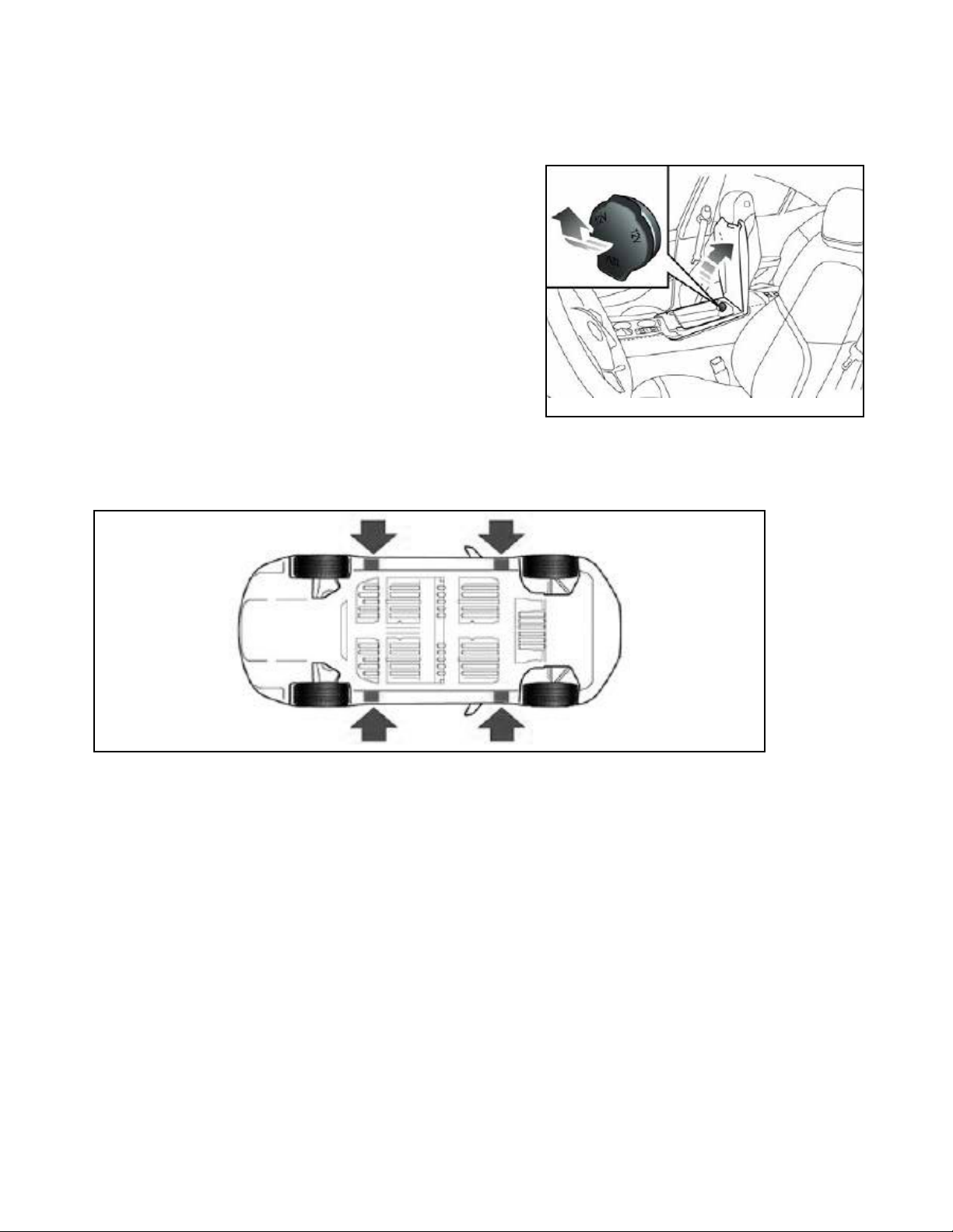
SELECTING NEUTRAL:
If the vehicle’s touchscreen can be activated to
select Neutral:
With the vehicle ON, make sure the vehicle is in
park, depress the brake pedal and put the vehicle
into TOW MODE using the touchscreen.
NOTE:The vehicle will remain in Neutral until
shifted to Park. However, if the vehicle has a low
charge, it will automatically shift to park and set
the parking brake. As a warning prior to this hap-
pening, the vehicle’s horn will sound.
Car Carrier Loading Procedures:
• Before loading, if possible, place the vehicle in Neutral with the parking brake released. Only load the
vehicle onto the car carrier enough to safely transport the vehicle. Stop loading when the winch line begins
to pull the vehicle downward. To prevent excessive downward pull, keep the leading edge of the vehicle at
least 2 feet from the winch drum (this will vary based on the towing equipment being used).
• When the vehicle is in its loaded position on the car carrier with the bed still in the deployed position,
secure the vehicle to prevent it from rolling by chocking the wheels and attaching one wheel strap to the
wheel closest to you. Continue to secure the vehicle until all four wheels are secure.
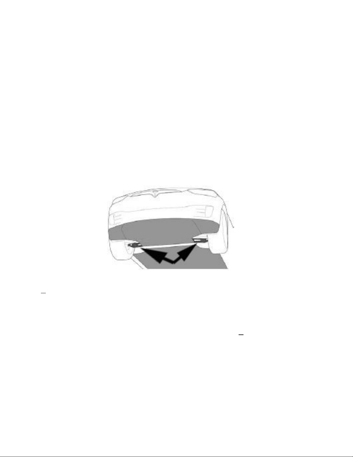
• Clearance around the wheel is limited and careful routing of straps is needed to avoid contacting brake
lines and wheel speed sensor wires, especially behind the front wheels. Careful routing of the straps is also
important to avoid contact with the painted surfaces of the vehicle.
• Once the bed is in its transport position and the vehicle is secured to the bed with four wheel strap tie-
downs, place the vehicle into Park to help secure the vehicle. Also ensure the vehicle is OFF and the elec-
tronic key is removed from the vehicle.
• After securing, slacken the winch line slightly to prevent any downward pull on the vehicle during trans-
port.
8
ELECTRONIC PARKING BRAKE:
These vehicles are not equipped with a conventional parking brake. The parking brake is engaged and disen-
gaged depending on the gear selected. There is no known override in the event of a failure in the system.

9
NOTE: Prior to loading Models S & X, make sure the air suspension (if equipped) is set
to JACK mode using the touchscreen. This setting can be found in the vehicle controls
section of the touchscreen. Failure to set the vehicle to JACK mode will likely result in
costly damages to the suspension.
Observe all standard jacking precautions and place the jack in its proper location. Ensure
thevehicleisonrm,levelgroundandthatthewheelsarechocked.Asthejackcomes
in contact with the vehicle body, ensure that it is contacting the correct location on the
vehicle and will not cause damage. Continue lifting to raise the vehicle just high enough
to perform the service needed.
TIRES AND JACKING:
Thisvehiclecomesequippedwithaninatorkitlocatedunderthetrunkoorpanel.
Tire Pressure:
Proper tire pressure can be found on the tire placard located on the driver’s side door pillar. Tire
pressure settings are also listed in the vehicle owner’s manual.
Jacking Locations
The accessory power outlet is located inside the
front center console. The vehicle has to be ON for
the accessory power outlet to work.
CAUTION: Make sure to secure the vehicle using
wheel chocks prior to service.
NOTE:Onlyusetheinatorkitasalastresort.
Accessory Power Outlet for Inator Kit:
Wheel Torque (All Models) = 129 lb. ft. (175 Nm)

10
HIGH-VOLTAGE SYSTEM:
NOTE: The high-voltage battery is not accessible. The high-voltage battery is located in
theoorofthevehicle.
Battery Type: Liquid-cooled Lithium-ion HV battery
BatteryVoltage:300-360volts
CAUTION: Avoid all contact with orange loom because this connects the electrical mo-
tors and generator (powered by the gas engine) with the high-voltage components.
This vehicle is equipped with a mechanical release in the event the high-voltage battery charge cord
will not release.
NOTE: Make sure power to the charge cord has been terminated by making sure the charging screen
is not showing on the touchscreen prior to attempting this procedure.
The emergency release is located inside the trunk on the driver’s side as shown below.
CHARGE PORT EMERGENCY RELEASE:
Model S
Model X
Model 3
Model 3 Model S Model 3

11
JUMP-START PROCEDURES:
NOTE: These vehicles may not have enough 12v battery power to unlock the doors or open the hood using the
touchscreen. If this occurs, refer to the HOOD RELEASE section on page 5 to access the 12v battery.
The following jump-starting procedures should be followed for all models:
• Follow all normal jump-starting precautions as outlined in other AAA/CAA publications.
• Ensure that all electrical accessories and the ignition are turned OFF and the electronic key is removed
from the vehicle and stored at least 15 feet away from the vehicle before connecting jumper cables or a
jumper box.
For the latest updates from AAA, visit: AAAcampus.aaa.biz
Model 3:
The battery is located under a plastic cover near the bulk-
head. Remove the cover by lifting straight up and place
where it will not be damaged. Then remove the air intake by
releasing 4 plastic clips and store where they will not be lost
or damaged.
• Connect the positive to the battery positive
• Connect the ground to a good, conductive non-paint-
ed surface
• Allow the 12v battery to charge a few minutes till
the touchscreen can be accessed
• Disconnect jump leads in the reverse order
Model 3
Model S:
The battery and dedicated jump pin are located under a
plastic cover near the bulkhead. Remove the cover by lifting
straight up. Place it where it will not be damaged.
• Connect the positive to the dedicated jump pin locat-
edinthefusebox.Itisidentiedbythearrowinthe
Model S image
• Connect the ground to a good, conductive non-paint-
ed surface
• Allow the 12v battery to charge a few minutes till
the touchscreen can be accessed
• Disconnect jump leads in the reverse order
Model S
Model X:
The battery’s jump pin is located under a plastic cover near
the bulkhead. Remove the cover by lifting straight up and
place where it will not be damaged.
• Connect the positive to the dedicated jump pin
locatedinthefuseboxidentiedbythearrowinthe
Model X image
• Connect the ground to a good, conductive non-paint-
ed surface
• Allow the 12v battery to charge a few minutes till
the touchscreen can be accessed
• Disconnect jump leads in the reverse order
Model X
Other manuals for 3 2018
1
This manual suits for next models
5
Table of contents
Other Tesla Electric Vehicle manuals