Test Equipment Depot Net Chaser TNC950AR User manual

2
Table of Contents
Introduction..................................................................................................... 3
Kit Contents ................................................................................................. 4
Optional Accessories. .................................................................................. 5
Safety Information
. ...................................................................................... 6
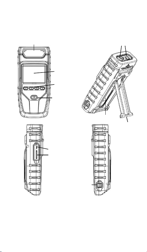
Net Chaser Description. ............................................................................... 7
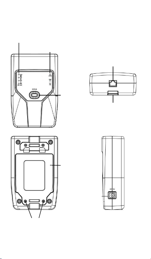
Active Remote Description. ......................................................................... 8
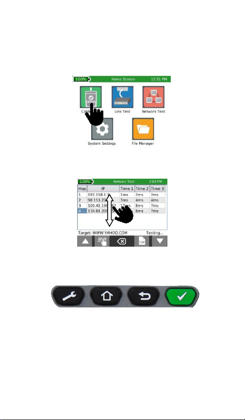
Net Chaser Touch Screen and Buttons. ....................................................... 9
General Operations
. .................................................................................. 10
System Settings. ............................................................................................ 11
First System Settings Screen (IP Setup) ..................................................... 11
Second System Settings Screen (Language).. ............................................ 12
Third System Settings Screen (Display Settings). ...................................... 12
Fourth System Settings Screen (Time and Date) ....................................... 13
Fifth System Settings Screen (Timeout Settings) ...................................... 14
Sixth System Settings Screen (User Information)...................................... 14
Seventh System Settings Screen (Firmware)............................................. 15
Eight System Settings Screen (Firmware/Hardware versions).................. 18
Active Remote ................................................................................................ 20
Cable Test ...................................................................................................... 21
Cable test Overview ...................................................................................... 22
Cable Test Setup
........................................................................................ 23
Cable Type ............................................................................................................... 24
New Cable Type .................................................................................... 24
Edit Existing Cable Type ........................................................................ 25
Select Cable Type .................................................................................. 25
Cable Name ........................................................................................... 25
Ethernet Cable Test............................................................................... 25
Cable Faults ............................................................................................... 26
Saving Cable Tests as PDF .......................................................................... 27
Saving a PDF Report. ............................................................................................. 27
Saving Test List as CSV ............................................................................... 28
Create a new Test List
............................................................................... 28
File Manager .............................................................................................. 29
Link Test
......................................................................................................... 29
Port Discovery ........................................................................................... 29
POE Test ..................................................................................................... 29
Tone ............................................................................................... 29
Link Light .................................................................................................... 30
BERT Only Test ........................................................................................... 31
Network Test ................................................................................................. 32
Link Test ..................................................................................................... 32
DHCP
.......................................................................................................... 32
Ping Test
.................................................................................................... 33
Trace Route................................................................................................. 33
VLAN ........................................................................................................... 34
Discovery Protocols
................................................................................... 35
File Manager
.................................................................................................. 36
USB Mode
...................................................................................................... 36
Icon Glossary .................................................................................................. 38
Frequently Asked Questions ............................................................................ 40
Maintenance................................................................................................... 44
Customer service ............................................................................................ 45
Specifications .................................................................................................. 46
Warranty Information
. .................................................................................. 47

3
The Net Chaser Ethernet Speed Certifier offers a complete solution to
test copper cables. The Net Chaser performs speed certification to
test the data-carrying capabilities of electrical Ethernet network cable
up to 1 Gb/s by testing for noise in the network, detecting faults in the
cable wiring, and ensuring that cables are able to support the speed
capabilities of active equipment.
To certify Ethernet speed performance of copper cable runs, the Net
Chaser handheld tester conducts Bit Error Rate (BER) tests by sending
data packets down specified cable runs at defined data rates to check
for errors at the maximum throughput of the link. The Net Chaser also
reports on signal quality that can impact high-speed data transmission
by measuring signal to noise ratio (SNR). Skew measurements report
on the signal time delay between pairs that can impact Ethernet data
transmission. The Net Chaser also provides continuity testing that
detects opens, shorts, miswires, split pairs, reversals, and high-
resistance faults while accurately measuring distance to faults and
total cable length.
The Net Chaser includes a comprehensive set of features for testing
active network capabilities: measure Power over Ethernet (PoE) to
ensure the correct power is available on the correct pins, use Port
Discovery to ensure the correct speed and duplex capability are
available; connect at gigabit Ethernet and run ping tests to verify
connectivity to IP hosts; discover network devices using Cisco
Discovery Protocol (CDP) or Link Layer Discovery Protocol (LLDP);
VLAN discovery; Trace Route function displays the path internet
packets travel to reach a specified destination. The Net Chaser also
saves test reports and exports to PCs.
INTRODUCTION

4
Net Chaser
The Net Chaser comes in one kit that will cover all your needs.
TNC950AR
▪Net Chaser main unit
▪Active remote
▪Power supply (2)
▪Network patch cables (2)
▪RJ45 Port Saver cables (2)
▪4GB SD card
▪Micro USB cable
▪Hanging strap with Carabineer clips (2)
▪Large Carrying Case
▪User Manual
Part Number
Description
NOTE
To optimize the life of the rechargeable
Lithium-Ion battery, please fully charge and
fully exhaust the battery in the tester three
times before charging the battery at mid-
levels.

5
Optional Accessories
P/N
Description
T138
#1-8 Network Testing and ID Remotes
TRK120
#1-20 ID Only Coax Remotes (Not for RF testing)
TRK220
#1-20 ID Only Network Remotes (Mapping only)
TAK030
Network Accessory Kit includes:
(4x) 1ft. network patch cables,
(2x) RJ45 to 8-way alligator clips,
(2x) F-Jack to BNC adaptor,
(2x) RJ45 Port Savers
TAR104
Net Chaser Active Remote with selectable ID's #1-
#4
TP150
Tone & Probe kit
TAK010
Hanging strap with carabineer clip
TPS120
AC to DC Power Supply: 12V 2.5A
Includes international adapter plugs NA/EU/AU/UK
21025C
RJ45 Port Saver for extending life of modular plug
TCA015
24 inch cable assembly 8-way alligator clips to RJ45
TCA016
1 ft. Network patch cables
4007
Hanging pouch
18301
F-Connector coupler (F81)

6
Safety Information
To ensure safe operations of the Net Chaser, follow instructions carefully
and observe warning and caution messages in this manual. Failure to
observe warnings can result in severe injury or death and can damage
the
equipment.
Warning/caution: potential for personal injury or damage
to equipment
Voltage!
Warning: hazards could cause harm or death
Conformité Européenne. Conforms to European Economic
Area directives.
Warning! To avoid possible fire, electric shock, or personal
injury:
Do not open the case; no user-serviceable parts are inside.
Do not modify the tester.
Do not use the tester if it is damaged. Inspect the tester
before use.
The tester is not intended to be connected to active
telephone inputs, systems, or equipment, including ISDN
devices. Prolonged exposure to the voltages applied by
these interfaces may damage the tester.
The Lithium Ion battery pack should be serviced
by qualified personnel. Only the original battery
pack type should be used with this product.
Notification
Definition

7
Net Chaser Description
Modular Cable
Interface
LCD Touch
Screen
Menu
Buttons
Power
Button
Micro USB and
SD Card Slot
Kickstand
Battery Door
DC Charger
Plug
RJ45 Jack and
F-Connector

8
Active Remote
Battery
Charge Status
LED’s
Hook Strap Loop
Linked/Pass/Fail
LED’s
RJ45 Jack
Status
Button
Battery Door
D/C Charger Plug
Battery Door Screws

9
Net Chaser Buttons and Touch Screen
The Net Chaser features buttons and a full color capacitive touch
screen to allow for easy navigation.
Touch an icon to select an option
Touch and drag a list to scroll up or down or touch the Up/Down
arrows.
The Net Chaser buttons assist with Navigation, starting and
stopping a test.
Settings - The Settings button will display the settings menu. Pressing
the settings while in the settings menu will display additional menu
screens.
Home - The Home button will display the home screen from any
menu.
Back - The Back button will display the previous screen.
Test - The Test button will start/stop a test.
Settings
Home
Back
Test

10
On/Off
▪
Turn Net Chaser on by pressing the Power button .
▪
Tap the Power button to put the Net Chaser in sleep mode.
▪
Press and hold the Power button
to power the unit off.
AutomaticPowerDown
The Net Chaser automatically enters sleep mode to conserve battery
power
if no input or activity is performed on the device. See System
Settings
on
page 14 to adjust the length of time before the automatic power down
occurs.
Net Chaser Active Remote
▪Check the Active Remote battery status and last test result by
pressing the Status button
.
General Operations

11
The Net Chaser Setup consists of eight screens to configure the unit to the
user’s preference. Use the Settings button
to navigate through the
settings screens.
First System Settings Screen: IPV4 Setup
In the IPV4 setup screen, the Net Chaser’s network tests can be
configured to use DHCP or a Static IP addresses. The Net Chaser
can also be set to use a DHCP provided DNS or a fixed DNS IP.
▪
Turn the Net Chaser on by pressing the Power
button .
▪
Touch System Settings
on the home screen.
▪“Use DHCP” is set as default. To enter static IP’s touch “Use
Static IP” and enter the following:
- Touch “Set IP” and enter the Net Chaser IP address
using the numeric keypad, then touch OK.
- Touch “Set Subnet Mask” and enter the Subnet Mask
IP address using the numeric keypad, then touch OK.
- Touch “Set Gateway” and enter the Gateway IP
address, then touch OK.
▪Use “DHCP DNS” is set as default. To manually enter DNS
addresses, touch “Choose DNS”.
▪Touch “Set DNS” and use the numeric keypad to enter a
preferred DNS IP address and touch OK.
System Settings

12
Second Systems Settings Screen: Language/Date
Format
Language
Select the desired Language.
Date Format
Select the desired date format:
month/day/year or day/month/year
Third System Settings Screen: Display Settings
Length settings:
▪
Under Display Units, touch either Feet or Meters.
▪Under “Standard”, touch either T568A or T568B. The touched
wiring standard will be displayed in the cable test wiring
diagram
.
LCD screen brightness:
▪
T
o the right of Brightness, touch Set.
▪
E
nter a number between 5 and 100 then touch OK. To
cancel, press the Back button .
▪
To continue, touch More Settings or press the Settings
button.

13
Fourth System Settings Screen: Display Units
Set time/clock/date:
▪
Under Time Format, touch either 12-hour or 24-hour format.
▪
To the right of Hours (1–12), touch Set Hour. Enter the hour you wish to
display then touch
OK
.
▪
To cancel, press the Back button
.
▪
To the right of Minutes (0-59), touch Set Minute. Enter the minutes
you wish to display then touch OK. To cancel,
press the Back button
.
▪
Under AM/PM, touch AM or PM on the screen.
▪
Under Date, set the month, day, and year: Touch Set Month. Enter the
number of the month, and then
touch
OK
. To cancel, press the Back
button
.
▪
Touch Set Day. Enter the number of the day, and then touch
OK
. To cancel, press the Back button
.
▪
Touch Set Year. Enter the year (all four digits), then touch OK.
To
cancel, press the Back button
.
▪
To continue, touch More Settings or press the Settings button
.

14
Fifth System Settings Screen: Timeout Settings
▪To set Standby power down:
▪
Touch Set to the right of Stand-by (default is 10 min).
▪Enter a whole number from 1-10 for the number of
minutes then touch OK. To cancel, press the Back
button
.
▪
To set System Shutdown Time:
▪
Touch Set to the right of System Shutdown (4 hour is the default
setting).
▪
Touch the number between 1 and 8 for the hours before system
shutdown then touch OK. To cancel, press the Back button
.
▪
To configure .tst file backup to SD, touch Disable/Enable. This
allows the test files to be saved to the SD card in the event of
critical memory loss.
▪
To continue, touch More Settings
or press the Settings
button
.
Sixth System Settings Screen: User Information
The User Information screen allows the user to enter Company name, user’s
name, and email to be included on the Net Chaser test reports.

15
▪Touch Set Company and use the keypad to enter the
company name (Max 20 Characters) then touch OK.
▪Touch Set Name (Max 20 Characters) and use the keypad to
enter a name then touch OK.
▪Touch Set E-mail and use the keypad to enter an email
address then touch OK.
▪Touch Set Phone and use the keypad to enter a phone
number (20 characters maximum) then touch OK.
▪To include a company logo, copy the desired image from
your computer to the Logo folder on the Net Chaser SD
card. The image size cannot exceed 586x163 dpi. Touch the
“Enable/Disable” button to include the company logo.
Note: If the SD card does not have a logo folder, right click in
the SD Card dialog box and click on a new folder. Name the
new folder “logo”.
▪To continue, touch More Settings or press the Settings
button .
SeventhSystem Settings Screen (Firmware)
You can have more than one version of firmware on the SD card – all
firmware files on the SD Card will be displayed on this screen. Use the Up
and Down buttons to scroll through multiple firmware files.
▪The factory installed firmware revision (default firmware) is
displayed above the firmware file table.
▪The current firmware revision that is being used is
displayed above the firmware file table Current x.xx.

16
How toupdate the Net ChaserFirmware:
Warning! Do not update the firmware if the battery charge is less
than
50%, unless the Net Chaser is plugged in to A/C power.
▪Go to
http://www.platinumtools.com/support/software-
updates/
▪Download the firmware file to your computer. Take
note of where the Firmware file is saved.
Upload firmware using the SD Card:
▪
Remove the SD Card (located on the left side of Net Chaser)
and
insert it into your computer using an SD Card reader.
Your computer will recognize the SD
Card as a removable
drive. Open the removable drive folder and copy the firmware
file(s) from your computer to the removable drive
window.
Image files may be included as part of the update, be sure to
copy all files from the firmware update folder to the SD card.
Re-insert the SD Card into the Net Chaser.
▪
Proceed Installation; “Net Chaser Update” below to install
complete the update.
*
Note: When installing SD Card with firmware update refresh the
firmware table by exiting and then reentering the firmware
screen.
Upload Net Chaser firmware using the Micro USB cable:
▪Plug the included micro USB cable into the Net Chaser
then plug the other end of the cable into your
computer.
▪Touch File Manager .
▪Touch More Options .
▪Touch USB . The Net Chaser will reboot into File
Transfer Mode as shown in the image below.
▪
The Net Chaser will be recognized by your computer as a
removable drive. If your computer does not automatically prompt
you to view the removable drive, click on the windows start menu,

17
click on “Computer”, and then double click on the removable
drive.
Note: The removable drive may be listed in “Computer” as an SD
Card, as the Net Chaser simulates an SD Card reader.
▪
Navigate to the firmware file(s) that was saved to the computer
from . Right click on the firmware file(s) then click on “Copy”.
Image files may be included as part of the update. Be sure to copy
all files from the firmware update download.
▪
Navigate back to the Net Chaser removable drive and right click in
the removable drive window and click on “Paste”.
▪
Close the removable drive window then click on “safely remove
hardware” on your computers toolbar on the bottom left. Eject
“MQX Mass Storage Device”.
▪
Remove the micro USB cable from the Net Chaser.
▪
The Net Chaser will automatically reboot. Follow the instructions
below to complete the update.
Install Net Chaser Update:
▪From the home screen, Touch System Settings .
▪T
ouch More Settings
or press the Settings
button until the
firmware screen is displayed (7
th
settings screen)
.
▪
Update by touching the firmware file in the firmware table then
touch Update Firmware on the screen. A new screen will
appear,
confirming that you are updating firmware. Touch OK to
continue or
Cancel. Another window will appear: Updating
firmware.
Warning: Systemwillrebootafterupdate.Pleasemakesurebatteryisnotlow.
Press
OK
to continue or Cancel.
▪
To reset to the factory firmware, touch the Reload Factory
Firmware
. A new screen will appear, confirming that you are
deleting the firmware update and restoring to factory default. You
will be
prompted to touch
OK
to continue or Cancel to cancel. Net
Chaser
will then restart.
▪
To reset to the factory settings, touch Reset Settings .
A new
screen will appear, confirming that you are restoring factory
Cable
Type list. You will be prompted to touch
OK
to continue or Cancel
to cancel.

18
To Update the Bootloader:
Warning! If your Net Chaser currently has factory Boot version 3.03 or lower,
you must use a Windows 7, Vista, or XP computer to install the bootloader.
Bootloader 4.00 or greater is compatible with Windows XP/Vista/7/8.
▪
To download the Net Chaser bootloader, visit
www.platinumtools.com/netchaserdownloads.
▪
Download the Bootloader file to your computer.
▪
Connect the Net Chaser to your computer using the included USB
cable.
▪
Press and hold the wrench key , then press and release the
power button . The Net Chaser will display a solid color on
the touch screen and the Link LED will flash. You can release the
wrench key at this point.
▪
Open the removable drive named “Bootloader”.
▪
Copy and paste the bootloader file to the removable drive.
▪
Power off the Net Chaser, unplug it from your computer, and then
power it back on.
To Update the PIC firmware:
Warning! The PIC update requires a factory version of at least 00.23 to be
updated through the GUI. Please contact Platinum Tools technical support
for more information. Please see Firmware Hardware versions on page 19.
▪
To update the Net Chaser PIC firmware, visit
http://www.platinumtools.com/support/software-updates/.
▪
Download the Pic update file to your computer.
▪
Follow
“Upload firmware using the SD Card”
or
Upload Net
Chaser firmware using the Micro USB cable”
instructions on page
16 to upload the PIC update file to your Net Chaser.
▪
Go to the Net Chaser Firmware Update screen (7
th
Settings Screen)
and touch the PIC update file in the Firmware table.
▪
Touch the install firmware icon
A new screen will appear,
confirming that you are deleting the firmware update and restoring
to factory default. You will be
prompted to touch
OK
to continue or
Cancel to cancel. Net Chaser
will then restart.

19
Eighth System Settings Screen: Firmware/Hardware
Versions
This screen will display which versions of firmware and hardware are in
your Net Chaser.
Firmware
▪
Boot (initializes hardware, loads, and executes operating system)
▪
GUI (Graphical User Interface)
▪PIC (Net Chaser Processor)
Hardware
▪
Serial Number (Net Chaser MAC Address)
▪
Module revision (number of your updated module)
▪
Battery (type of battery)
▪
NAND size (flash memory in megabytes)
Press the More Settings soft key
to return to the first System Settings
screen or press the Home button
to return to the Home Screen.

20
The Active Remote is used with the Net Chaser to perform a speed
certification test. The Active remote can be configured to display 1-
4 remote ID’s
▪
Press the Status button to display the battery percentage and the
Pass/Fail result of the previous cable test.
▪
To set the remote ID, remove the battery door screws (see Active
Remote on pg.8) and remove the battery door.
▪
Gently pull out the battery (it is not necessary to unplug the battery to
access the ID indicator switch.
WARNING! Do not pull on the battery wires as this may damage the
battery. If the battery is removed, use caution as it plugs in one way.
Do not force the plug in to the remote as this will damage the plug
and/or remote.
▪
Push the desired ID switch up and push the other keys down (see image
below).
Active Remote
Remote set to ID 1
Table of contents
Other Test Equipment Depot Test Equipment manuals

Test Equipment Depot
Test Equipment Depot GPL-5010 User manual

Test Equipment Depot
Test Equipment Depot FHT-801 User manual

Test Equipment Depot
Test Equipment Depot Megger MPQ1000 User manual

Test Equipment Depot
Test Equipment Depot Rapport 337 User manual

Test Equipment Depot
Test Equipment Depot GOS-620 Instruction Manual

Test Equipment Depot
Test Equipment Depot teletalker 330 User manual

Test Equipment Depot
Test Equipment Depot 990DSL User manual

Test Equipment Depot
Test Equipment Depot Cable Prowler TCB300 User manual

Test Equipment Depot
Test Equipment Depot Net Prowler TNP700 User manual

Test Equipment Depot
Test Equipment Depot Druck DPI 811 User manual