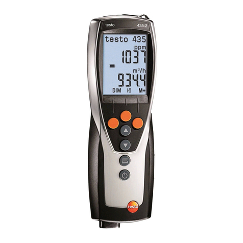
TESTO 0519.0816 User manual

Operation manual Pneumator ∙Testo Industrial Services ∙Version 1.4 ∙2019 ∙Page 1

Operation manual Pneumator ∙Testo Industrial Services ∙Version 1.4 ∙2019 ∙Page 2
Order number Measuring range
0519.0816 1 hPa
0519.0817 10 hPa
0519.0818 100 hPa
0519.0819 1000 hPa

Operation manual Pneumator ∙Testo Industrial Services ∙Version 1.4 ∙2019 ∙Page 3
Content
1. Introduction and safety instructions ................................................................ 4
2. Overview operation elements and interfaces .................................................. 5
3. Operating modes................................................................................................ 5
4. General operation............................................................................................... 6
5. Menu setting for all operating modes............................................................... 7
6. Operating mode CTRL – calibration (step-by-step)......................................... 8
7. Operating mode AUTO – calibration (programmed steps) ........................... 11
8. Operating mode MESS – Pressure measurement ......................................... 15
9. Operating mode VELO – Velocity measurement ........................................... 17
10. Operating mode FLOW – volume flow measurement ................................... 20
11. Computer programming .................................................................................. 22
12. Technical data .................................................................................................. 25
13. Trouble-shooting.............................................................................................. 23
14. Service .............................................................................................................. 26

Operation manual Pneumator ∙Testo Industrial Services ∙Version 1.4 ∙2019 ∙Page 4
1. Introduction and safety instructions
Dear Sir or Madam,
Thank you for buying a Pneumator from Testo industrial services GmbH.
We are sure, that this instrument will be of benefit to you and your work for a long
time.
Please read the operation manual carefully and get acquainted with the handling of
the Pneumator before you start operating.
Should a problem occur, which you are not able to solve yourself, please contact our
service department or your salesman. We will make every effort to help you as fast
and competent as possible.
Attention:
- The Pneumator is supplied via a power supply with 20 to 26 VDC at an
amperage of 1 A. Never touch parts under Voltage!
- The inserted reference sensor has an overload protection. However, please
note that the max. application of pressure is never exceeded, as otherwise
lasting destruction could occur:
oPneumators 1 / 10 / 100 hPa 5-times overload stability
oPneumators 1000 hPa 2-times overload stability
- Please note that a negative pressure at the minus connection may never
exceed 10% of the measuring range
- The Pneumator contains an accumulator (lithium manganese cells). This
should be unloaded occasionally, in order to optimize the performance.
- Concerning transport, the Pneumator must be packed shockproof in order to
avoid damages!
- Please leave the device closed. When opening the device the warranty
expires.

Operation manual Pneumator ∙Testo Industrial Services ∙Version 1.4 ∙2019 ∙Page 5
2. Overview operation elements
The Pneumator has two pressure connections, one display as well as 9 control
buttons:
Pressure „+“ With differential pressure, the higher pressure must be attached here
With relative pressure, please attach only to this connector
Pressure „-“ With differential pressure, the lower pressure must be attached here
Display Depending upon selected mode of operation all relevant
information is shown here.
The operating keys are described in the section „general instruction information“
Interfaces:
On the back of the Pneumator, you will find the following interfaces:
- Voltage supply (20..26 VDC, 1 A, min. 30 W, by provided power supply)
- RS232
- USB
3. Operating modes

Operation manual Pneumator ∙Testo Industrial Services ∙Version 1.4 ∙2019 ∙Page 6
Operating
mode
Page Application Pressure connection Function
CTRL 8 Calibration
(step-by-step)
Test device (Differential-/
relative pressure measuring
instrument)
Pump builds up selected
pressure, display indicates the
reference sensor value
AUTO 11 Calibration
(programmed)
Test device (Differential/
Relative pressure instrument)
As CTRL, with pre-
programmed steps
MESS 15 Pressure
measurement
Differential
pressure
Relative
pressure
Process pressure…
…connect to „Plus“ and
„Minus“
…connect to „Plus“
Pump deactivated,
Display indicates the pressure
value of the reference sensor
VELO 17 Velocity
measurement
Pitot tube (air duct) As MESS, however velocity
display
FLOW 20 Volumetric
flow-
measurement
Pitot tube (air duct) As MESS, however Volume
flow display
4. General operation
Each mode of operation is programmed at first (in the menu and/or in its submenus),
before it is used. Programming is done as follows:
oUsually by operating buttons (in this description always written in capital
letters). Their function is described below.
oBy the RS232 or USB interface (see the chapter „computer programming“)
o
Overview control-buttons:
I/O On-off switch. Function of the off switch:
In the mains operation it is switched to battery charge.
In battery operation the instrument is switched off.
MENU During operation: Start menu programming
In the menu: Leave menu, start application
In the submenu: not applied
OK During operation: see description of the individual operation mode
In the menu: Choose submenu
In the submenu: leave submenu, store set values
UP During operation: see description of the individual operation mode
In the menu: next line
In the submenu: value +1
DOWN During operation: see description of the individual operation mode
In the menu: previous line
In the submenu: value -1
0% During operation: see description of the individual operation mode
In the menu: without function

Operation manual Pneumator ∙Testo Industrial Services ∙Version 1.4 ∙2019 ∙Page 7
In the submenu: one decimal to the left
100% During operation: see description of the individual operation mode
In the menu: without function
In the submenu: one decimal to the right
LEAK Tightness test (between the test device and the reference sensor), at
CTRL and AUTO without function
ZERO Manual zero setting of the reference sensor
5. Menu settings for all operating modes
In this section the settings are described, which are relevant for all modes of
operation. All further settings, you will find described in the respective chapters.
oPress MENU
oSubmenu „Language“: Change menu language (buttons UP, DOWN,
confirming with OK).
oSubmenu settings: At OK a further menu overview is being opened.
oSubmenu zero: At zeroing the reference pressure sensor is being
pressurized with the differential pressure = 0 Pa, by opening internal
electromagnetic valves. This can be done manually (ZERO) or in
automatic cycles (each duration approx. 5 s). The setting is done in the
following submenus.
Submenu Auto-Zero: Activated = „ON“ / deactivated =
„OFF“ (buttons UP, DOWN, confirm with OK)
Submenu interval: Value range 1 .. 60 minutes selectable
(buttons UP, DOWN, 0%, 100%, confirm with OK)
Leave submenu by pressing MENU
oSubmenu RS232/USB: compare with „programming via PC“
oSubmenu display: The brightness is defined in another submenu.
Submenu „brightness “: Adjustment of the display brightness .
Range of value 0% to 100% (buttons UP, DOWN, 0%, 100%,
confirm with OK).
oSubmenu info: Equipment specification about the measuring range,
firmware and hardware

Operation manual Pneumator ∙Testo Industrial Services ∙Version 1.4 ∙2019 ∙Page 8
6. Operating mode CTRL – calibration (step-by-step)
Purpose:
The operation mode CTRL (Control / regulation) is selected for the calibration of a
test device in individual steps. In case the calibration takes place at the same
pressure ranges frequently, we recommend the operation mode AUTO.
Device function and schematic diagram:
In the operation mode CTRL the pump is turned on and regulates
in each case the requested pressure set point value. Thereby the
internal reference pressure sensor, whose measured value is
shown in the display in each case, supplies the actual pressure
value.
Connection of the test device:
Differential pressure test device: Connect to „Plus“ and „Minus“.
Relative pressure test device: Connect to „Plus“.
Programming:
oPress MENU
oSubmenu „Mode“: press UP or DOWN until CTRL appears. Selecting with
OK.
oSubmenu „Range“: Define maximal calibration pressure (buttons UP,
DOWN, 0%, 100%, confirming with OK). Possible value ranges compare
chart.
Pneumator type Minimal value Maximal value
0519.0816 -0,1 hPa 1,1 hPa
0519.0817 -1 hPa 11 hPa
0519.0818 -10 hPa 110 hPa
0519.0819 -100 hPa 1100 hPa
oSubmenu „Unit“: Define requested pressure unit (buttons UP and DOWN,
confirm with OK). The maximal calibration pressure (Submenu „Range“) is
being calculated automatically.
oSubmenu „Steps“: Define requested (percental) step rate (buttons UP,
DOWN, 0%, 100%, confirm with OK).
oExample: at range/unit = +1.000 hPa and steps = the following pressure
sequence is provided: 0 hPa, then 250 hPa, then 500 hPa, then 750 hPa, and
finally 1.000 hPa pressure.
oSubmenu „Setting Zero“: Definition of automatic zero procedure
oAuto zero = ON: right after leaving the menu, and then on a regular
basis the zero points gets adjusted
oInterval: Time Distance in minutes between two zero adjustments
oLeave the menu by pressing the MENU button
Operation manual Pneumator ∙Testo Industrial Services ∙Version 1.4 ∙2019 ∙Page 9
Operation / application:
After selecting the operation mode CTRL and leaving the menu (MENU button) a
zero adjustment is automatically conducted, in case AUTO ZERO = ON.
Subsequently, the reference sensor is venting („VENT “).
The respective pressure set point value now results now from the nominal pressure
value (see upper display middle, initial value = full measuring range), multiplied by a
percentage value (see lower display middle, initial value = 0%). The respective set
point value is indicated in the lower right display, the unit in the upper right. Note: The
new set point value is activated immediately after the change of the absolute value or
of the percental value.
Example (compare illustration):
- Nominal value: 100.00 Pa
- Percental value: 0%
- Current set point value = 100 Pa * 0% = 0 Pa
You can switch between the absolute value and the
percental value by pressing OK.
Change of the percental value (lower display middle - framed bold):
For the gradual up - and down regulation of the pressure value, e.g. 0 / 25 / 50 / 75 /
100 % of the absolute value. The step size x is defined in the submenu „range“ .
UP: Pressure rise of x % of the measuring range
DOWN: Pressure reduction of x % of the measuring range
0%: Pressure = 0 Pa
100%: Pressure = 100% of the measuring range
Change of the absolute value (upper display center - framed bold):
For the start-up of a given pressure value, e.g. 610 hPa. In most cases it is advisable
to leave this value on 100% of the measuring range.
UP: Digit +1
DOWN: Digit -1
0%: one digit position to the left
100%: one digit position to the right
Retrieval of the calibration data:
As soon as the central display figure indicates a stable value, the respective
calibration data can be retrieved:
- physical unit: Display value upper right
- pressure set value: Display value in the lower right
- actual value of test device: Display of the test device
- Reference value: Display middle
Manual zero balance (ZERO)
In case the reference measuring cell is to be set to zero during the calibration, please
use the ZERO button. After approximately 3-5 seconds, the previous status is started
up again.

Operation manual Pneumator ∙Testo Industrial Services ∙Version 1.4 ∙2019 ∙Page 10
Leakage test (LEAK)
In case the test device has to be checked whether it is connected pressure-tight, you
can start a leakage test with the LEAK button at each pressure step, upon reaching a
stabilized value. The pump is now switched off; the middle display value shows
whether a stable value is being held or whether the pressure value sinks. Pressing
the LEAK button again, you return to the CTRL operating mode.
Example (see display photo):
- Lower left: time since pressing LEAK in s, here 89 s
- Lower middle: Pressure change in % since pressing
LEAK, here increase by approx. 1%
- Lower right: Absulute Pressure change, here by
+0,099 hPa
Leaving the operation mode CTRL
When pressing the MENU button, the Pneumator is first driven into the VENT mode
(venting) in order to reduce the internal pump pressure. By pressing the MENU
button again, the operation menu is shown. In the submenu “Modus” another mode
of operation can be selected.

Operation manual Pneumator ∙Testo Industrial Services ∙Version 1.4 ∙2019 ∙Page 11
7. Operating mode AUTO – calibration (programmed steps)
Purpose:
The operation mode AUTO (automatic regulation) is chosen for the calibration of test
devices in preprogrammed steps. This makes sense and is timesaving if several test
devices have to be calibrated with the same pressure sequences.
Device function and schematic diagram:
The operation mode AUTO has the same device functions as the
calibration mode CTRL. Additionally a pressure sequence can be
started once or several times by a simple program.
The pump is on and regulates the respective pre-programmed set
pressure value. The internal reference pressure sensor, whose
measured value is shown in the middle of the display in each case,
supplies the actual pressure value.
Connection of the test device:
Differential pressure test device: Connection to „Plus“ and „Minus“.
Relative pressure test device: Connection to „Plus“.
Programming:
oPress MENU
oSubmenu „Mode“: press UP or DOWN until AUTO is indicated. Selecting
with OK .
o
Note: The sub menus „range“, „unit“, „steps“ in the main menu is of no
importance in AUTO, therefore it can remain unchanged.
oSubmenu „Settings“: By pressing OK, a further menu overview is opened, in
which at this stage only the submenu „Auto-Modus“ is relevant.
oSubmenu „Auto-Mode“ selecting with OK
Submenu „range“: Define maximum calibration pressure
(buttons UP, DOWN, 0%, 100%, confirm with by OK). Possible
value ranges see chart.
Pneumator type Minimal value Maximal value
0519.0816 0,1 hPa 1,1 hPa
0519.0817 1 hPa 11 hPa
0519.0818 10 hPa 110 hPa
0519.0819 100 hPa 1100 hPa
Submenu „Unit“: Define requested pressure unit (buttons UP
and DOWN, confirming with OK). The maximal calibration
pressure (Submenu „range“) is being converted automatically
Submenu „Steps up“: Define requested number of rising
pressure steps (buttons UP, DOWN, 0%, 100%, confirm with
OK).
Example: at range/unit = +1.000 hPa and „Steps up“ = 4 the
sequence is: 0 hPa, then 250 hPa, then 500 hPa, then 750 hPa,
and finally 1.000 hPa.

Operation manual Pneumator ∙Testo Industrial Services ∙Version 1.4 ∙2019 ∙Page 12
Submenu „Steps down“: Define requested number of
descending pressure steps (buttons UP, DOWN, 0%, 100%,
confirm with OK).
Submenu „Configuration 1“: By pressing OK, a further menu
overview is being opened. The meaning of the variables is also
clarified in the following illustration.
Submenu „Cycles“: Here is being defined how often the
pressure sequence shall be repeated (buttons UP,
DOWN, 0%, 100%, confirm with OK).
Submenu „T Start“: Initial waiting time for the venting
(buttons UP, DOWN, 0%, 100%, confirm withOK),
compare illustration and chart
Submenu „T Stop“: Waiting time at maximum pressure
(buttons UP, DOWN, 0%, 100%, confirm with OK),
compare illustration and chart
Submenu „T Hold“: Holding time of each adjusted
pressure stage (buttons UP, DOWN, 0%, 100%, confirm
with OK), compare illustration and chart
Submenu „T Pause“: Pause time between 2 cycles
(buttons UP, DOWN, 0%, 100%, confirm with OK),
compare illustration and chart
Submenu „Auto Zero“: Selection (buttons UP / DOWN,
confirm with OK), whether an automatically zero-ing shall
be driven as phase 4. ON = yes, OFF = no.
oLeave the menu by pressing the MENU button several times

Operation manual Pneumator ∙Testo Industrial Services ∙Version 1.4 ∙2019 ∙Page 13
Phase
number
Indication in
menu
Signification
1 Wait for start (activate with OK), equipment is venting
(display shows VENT)
2 T START Waiting time (in seconds) for venting (display shows
VENT)
4 Zeroing phase (if AUTO ZERO = ON), about. 3-5
seconds. At AUTO ZERO = OFF phase is dropped
7 T HOLD Holding time (in seconds) at point zero
9 Adjustment of the next higher pressure stage
10 T HOLD Holding time (in seconds) for adjusted pressure
(equivalent to the duration of phase 7)
13 T STOP Waiting time (in seconds) at maximum pressure
(„range“)
15 Adjustment of the next lower pressure stage
16 T HOLD Holding time (in seconds) at “pressure down” steps and
when reaching the zero point again (equivalent to the
duration of phase 7)
18 T PAUSE Pause time between 2 cycles
Operation / application (AUTO):
After selecting the operation mode AUTO and leaving the menu (MENU button) the
AUTO display appears which supplies all relevant information for the automated
calibration procedure. The device is now in phase 1
(Waiting for OK = start).
The meaning of the display elements (AUTO):
oTop left: Indication of the current operation mode
oVENT = venting
oZERO = zeroing
oCTRL = Adjustment and holding of the programmed pressure stages

Operation manual Pneumator ∙Testo Industrial Services ∙Version 1.4 ∙2019 ∙Page 14
oUpper middle and right: Indication of the maximum pressure and unit
oMiddle left: Number of past and future cycles
oMiddle: Phase number (compare chart above), phase-duration, reference
pressure value
oBottom to the left: Battery load indicator (at mains operation: plug symbol)
oBottom in the middle: percental indication of the current set pressure stage (in
percent of the maximum pressure)
oBottom right: Absolute value of the current set pressure stage.
Example (see illustration):
- Maximum pressure = 10 mbar
- Currently phase 1 (waiting for OK), venting
- Currently pressure = 0,002 mbar,
- first of ten cycles
- power supply operation (lower left)
Retrieval of calibration data:
The programmed calibration cycles will be started by the OK button. As soon as the
display (middle) indicates a stable value in the phases 10 or 16, the adequate
calibration data can be registered (please note: the values will not be stored):
- Physical unit: Value in the upper right of the display
- Set value: value in the lower right of the display
- Actual value of the test device: Display of the test device
- Reference value: Middle of display
Leakage test (LEAK)
The leakage test is not available in the AUTO-Modus.
Leaving the operating mode AUTO
Pressing the MENU button, the AUTO-Modus will be canceled and left at any time.
While the menu is shown, the equipment is venting (VENT) in order to reduce the
internal pressure of the pump. If desired, you can switch to another mode (CTRL,
MESS).

Operation manual Pneumator ∙Testo Industrial Services ∙Version 1.4 ∙2019 ∙Page 15
8. Operating mode MESS – Pressure measurement
Purpose:
The operating mode MESS (pressure measurement) is used for measurement of
process pressure (differential pressure or relative pressure).
Device function and schematic diagram:
In the operating mode MESS the pump is turned off. The internal
reference pressure sensor immediately measures the pressure
value of the process.
Connection to the process:
oDifferential pressure process: Connection to „plus“ and
„minus“.
oRelative pressure process: Connection to „plus“.
Programming:
oPress the button MENU.
oSubmenu „Mode“: Press UP or DOWN, until MESS appears. Selecting with
OK.
oSubmenu „Unit“: Define the favored pressure unit (buttons UP and DOWN,
confirm with OK). The maximum measurement range is automatically
converted (in the upper middle of the MESS display).
oSubmenu „Setting Zero“: Definition of automatic zero procedure
oAuto zero = ON: right after leaving the menu, and then on a regular
basis the zero points gets adjusted
oInterval: Time Distance in minutes between two zero adjustments
oRemark: The submenus which are contained in the menu „Range“ and
„Steps“ are not relevant in MESS, they can remain unchanged.
Operation / Application (MESS):
After selecting the operating mode MESS and leaving the menu (MENU button) a
zero adjustment is automatically conducted, in case AUTO ZERO = ON. Thereafter
the MESS display indication appears which provides all relevant information of the
measurement.
Meaning of the display elements (MESS):
oTop left: Display of current operating mode (ZERO = zeroing, MESS =
measurement operation, ERR = overload error)
oIn the upper middle: maximum measurement range (cannot be changed, size
according to model)
oTop right: physical unit
oIn the middle: current pressure measurement value (of the internal pressure
sensor).
oBottom left: Rechargeable battery charger display (at mains operation: plug
symbol)

Operation manual Pneumator ∙Testo Industrial Services ∙Version 1.4 ∙2019 ∙Page 16
Example (see illustration):
- Operating mode pressure measurement
(MESS)
- Maximum pressure = 10 mbar
- Current measurement value = 0 mbar
- Current pressure = 0,002 mbar,
- Mains operation (bottom left)
Protection against overload:
IMPORTANT: Please bear in mind that the connected pressure does
not exceed 125% of the measurement range of the Pneumator. If this
happens slowly, the internal magnetic valve will lock at this value and
ERR appears in the display. Make sure that the high pressure is no
longer present and unlock the equipment by pushing the button OK.
ATTENTON: If an overload occurs too quickly (approx. <1ms), the
pressure sensor can be destroyed.
Manual zero balance (ZERO)
In case the reference measurement element has to be set to zero during the
measuring procedure, please press the ZERO button. After approx. 3-
5 seconds the measurement operation will proceed again.
ERR
ZERO

Operation manual Pneumator ∙Testo Industrial Services ∙Version 1.4 ∙2019 ∙Page 17
9. Operating mode VELO – Velocity measurement
Purpose:
The operating mode VELO (velocity measurement) is used for the measurement of
process velocity (e.g. in an air duct) with the help of a pitot tube.
Device function and schematic diagram:
In the operating mode VELO the pump is turned off. The internal
reference pressure sensor immediately measures the differential
pressure value of the process. This value directly relates to the
velocity value, which is indicated on the display:
v = s * sqrt ( 2 * DeltaP / rho)
with
v = Velocity [m/s]
s = Pitot tube factor (without unit)
= 0.67 if a straight pitot tube
= 1.0 if Prandtl pitot tubes
rho = density [kg/m3]
DeltaP = Differential pressure [Pa]
sqrt = Square root
Programming:
oPress MENU
oSubmenu „Mode“: Press UP or DOWN, until VELO appears. Selecting with
OK.
oSubmenu „Unit“: Define the favored velocity unit (button UP and DOWN,
confirm with OK). The maximum measurement range (is indicated in the VELO
display upper middle) is automatically converted.
oSubmenu „Settings“: Here the submenu „“VELO-FLOW“ is relevant,
selecting with OK
oSubmenu „Density“: Enter the media density (e.g.. air at 20°C: 1.20
kg/m3)
oSubmenu „Pitot tube“: Enter the pitot tube factor
= 1.0 if straight pitot tube
= 0.67, if Prandtl pitot tube
oSubmenu „Setting Zero“: Definition of automatic zero procedure
oAuto zero = ON: right after leaving the menu, and then on a regular
basis the zero points gets adjusted
oInterval: Time Distance in minutes between two zero adjustments
oRemark: The submenus “range” and “steps” in the main are not relevant in
VELO, therefore they can remain unchanged.
Operation / application (VELO):
Connect the pitot tube pressure-tight to the equipment. The end of the pitot tube is
connected with the „Plus“- junction, the other pitot tube-junction with „Minus“.
After selecting the operating mode VELO and leaving the menu (MENU button), a
zero adjustment is automatically conducted, in case AUTO ZERO = ON. Thereafter

Operation manual Pneumator ∙Testo Industrial Services ∙Version 1.4 ∙2019 ∙Page 18
the VELO display indication appears, which provides all relevant information of the
measurement, appears.
Meaning of the display elements (VELO):
oTop left: Display of current operating mode (ZERO = zero setting, VELO =
velocity measurement operation, ERR = overload error)
oIn the upper middle: maximum measurement range (cannot be changed, value
according to model)
oTop right: physical unit
oIn the middle: current velocity measurement value (calculated from the
measurement value of the internal pressure sensor).
oBottom left: Rechargeable battery charger display (at mains operation: plug
symbol)
Example (compare illustration):
- Operating mode velocity (VELO)
- Maximum velocity = 40,825 m/s
- Current measurement value = 0 m/s
- Density = 1,2 kg/m3,
- mains operation (bottom left)
Protection against overload:
IMPORTANT: Please bear in mind that the connected pressure does not exceed
125% of the measurement range of the Pneumator. If this happens slowly, the
internal magnetic valve will lock at this value and ERR appears in the display. Make
sure that the high pressure is no longer present and unlock the equipment by
pushing the button OK.
ATTENTON: If an overload occurs too quickly (approx. <1ms), the pressure sensor
can be destroyed.
Manual zero balance (ZERO)
In case the reference measurement element has to be set to zero during the
measuring procedure, please press the ZERO button. After approx. 3-5 seconds the
measurement operation will proceed again.

Operation manual Pneumator ∙Testo Industrial Services ∙Version 1.4 ∙2019 ∙Page 19

Operation manual Pneumator ∙Testo Industrial Services ∙Version 1.4 ∙2019 ∙Page 20
10. Operationg mode FLOW – volume flow measurement
Purpose:
The operating mode FLOW (volume flow measurement) is used for measurement of
process-volume flow (e.g. in an air duct) with the help of a pitot tube.
Device function and schematic diagram:
In the operating mode FLOW the pump is turned off. The internal reference pressure
sensor immediately measures the differential pressure value of the process. This
value directly relates to the volume flow value, which is indicated on the display:
V = s * A * sqrt ( 2 * DeltaP / rho)
with
V = volume flow [m3/s]
s = pitot tube pressure factor (without unit)
= 0.67 if a straight pitot tube
= 1.0 if Prandtl-pitot tube
A = cross sectional area [m2]
rho = density [kg/m3]
DeltaP = differential pressure [Pa]
sqrt = square root
Programming:
oPress MENU
oSubmenu „Mode“: Press UP or DOWN, until FLOW appears. Selecting with
OK.
oSubmenu „Unit“: Define the favored volume flow unit (button UP and DOWN,
confirm with OK). The maximum measurement range (is indicated in the
FLOW display upper middle) is automatically converted.
oSubmenu „settings“: Here the submenu „VELO-FLOW“ is relevant, selecting
with OK.
oSubmenu „density“: Enter the density media (e.g.. air at 20°C: 1.20
kg/m3)
oSubmenu„pitot tube“: Enter the pitot tube factor
= 1.0 if a straight pitot tube
= 0.67, if Prandtl-pitot tube
oSubmenu „Area“: Enter the cross sectional area in the air duct [m2].
oSubmenu „Setting Zero“: Definition of automatic zero procedure
oAuto zero = ON: right after leaving the menu, and then on a regular
basis the zero points gets adjusted
oInterval: Time Distance in minutes between two zero adjustments
oRemark: The submenus „range“ and „steps“ in the main menu are not relevant
in FLOW, therefore they can remain unchanged.
Operation / application (FLOW):
Connect the pitot tube pressure-tight to the equipment. The end of the pitot tube is
connected with the „Plus“-junction, the other pitot tube-junction with „Minus“.
After selecting the operating mode FLOW und leaving the Menu (MENU button), a
zero adjustment is automatically conducted, in case AUTO ZERO = ON. Thereafter
This manual suits for next models
3
Table of contents
Other TESTO Measuring Instrument manuals