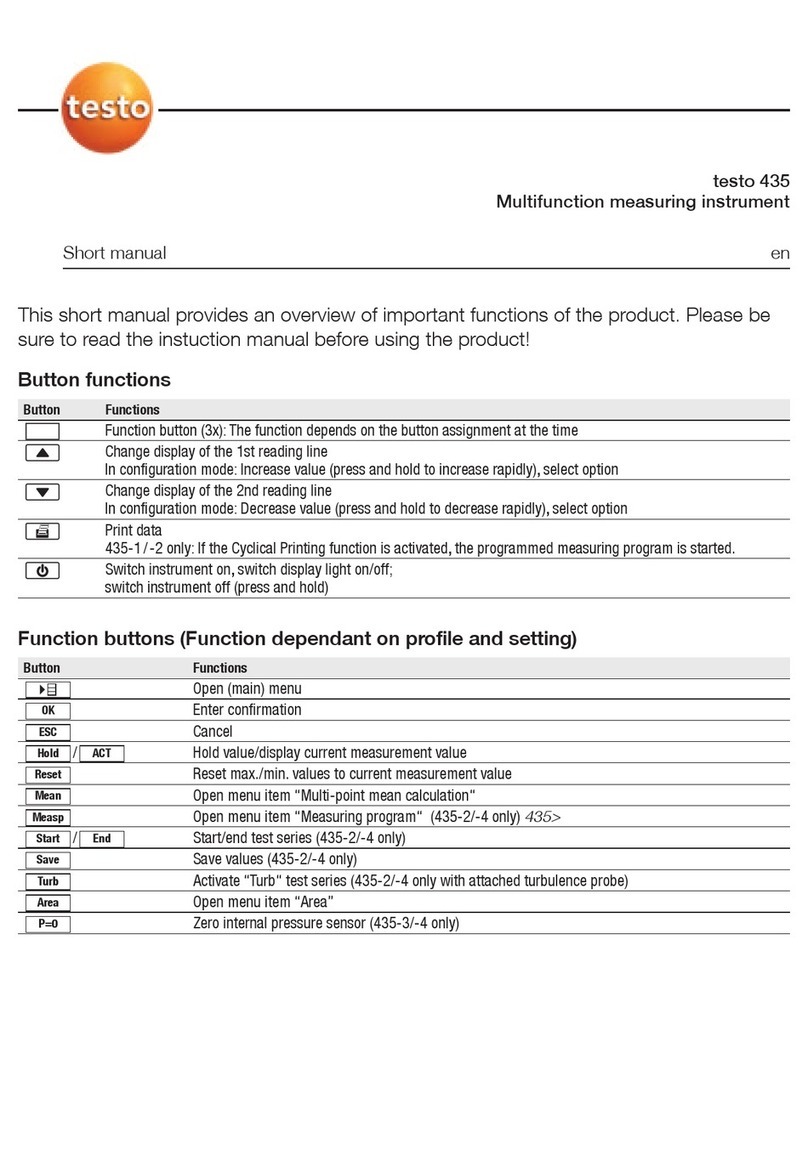
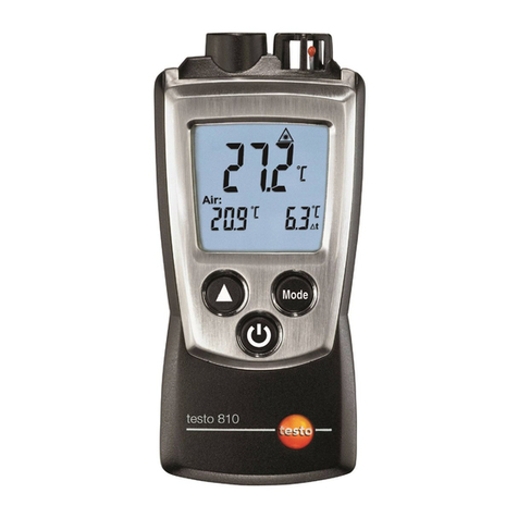
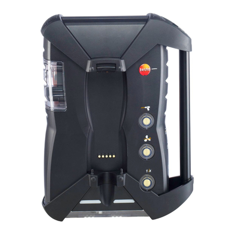
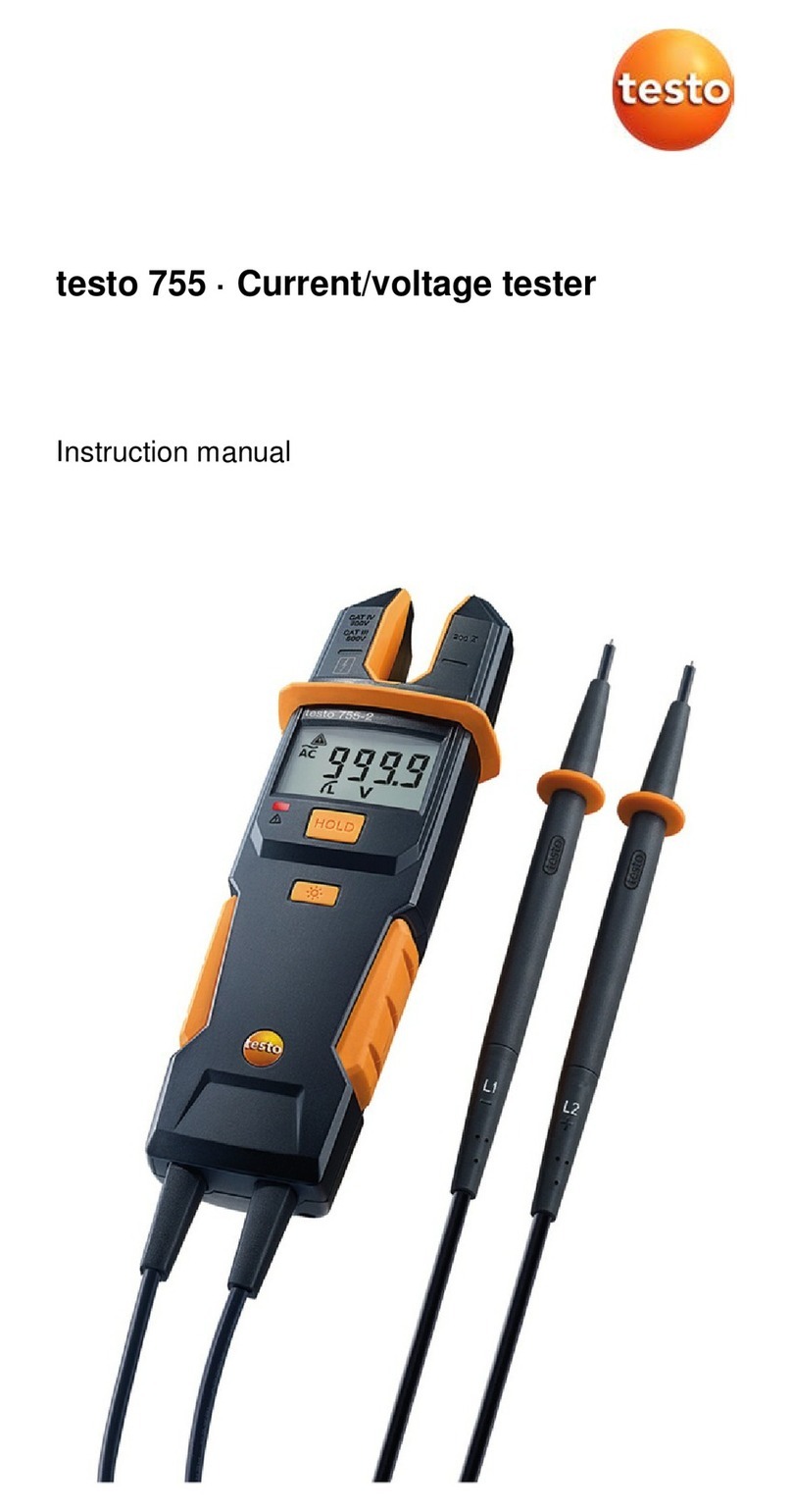
TESTO 350 Maritime V2 User manual

testo 350 MARITIME V2 · Flue gas analyzer
Instruction manual

2

1 Contents
3
1 Contents
1Contents ...................................................................................................3
2Safety and the environment....................................................................6
2.1. About this document........................................................................6
2.2. Ensure safety...................................................................................7
2.3. Hazard warnings..............................................................................8
2.4. Protecting the environment............................................................11
3Specifications ........................................................................................12
3.1. Use ................................................................................................12
3.2. Technical data ...............................................................................14
3.2.1. Declaration of Conformity ..............................................................................14
3.2.2. Measuring ranges and accuracies .................................................................15
3.2.3. Recommended test gas concentrations .........................................................16
3.2.4. Other instrument data ....................................................................................16
4Product description...............................................................................18
4.1. Scope of delivery ...........................................................................18
4.2. Control unit ....................................................................................19
4.2.1. Overview........................................................................................................ 19
4.2.2. Keyboard .......................................................................................................20
4.2.3. Display...........................................................................................................21
4.2.4. Connections / interfaces ................................................................................22
4.2.5. Menu guide for control unit ............................................................................22
4.3. Measuring box ...............................................................................23
4.3.1. Overview........................................................................................................ 23
4.3.2. Status display ................................................................................................24
4.3.3. Connections / interfaces ................................................................................25
4.3.4. Functions / instrument options .......................................................................26
4.3.5. Menu guide for measuring box.......................................................................26
4.4. Flue gas probe...............................................................................28
4.4.1. Overview........................................................................................................ 28
5First steps ..............................................................................................29
5.1. Commissioning ..............................................................................29
5.2. Getting to know the product...........................................................29
5.2.1. Mains unit, batteries/rechargeable batteries...................................................29
5.2.1.1. Recharging the rechargeable battery for the control unit .................30
5.2.1.2. Charging the rechargeable battery for the measuring box ...............30
5.2.1.3. Battery care .....................................................................................31
5.2.1.4. Mains operation...............................................................................31
5.2.2. Connecting probes / sensors .........................................................................32
5.2.3. Occupying the trigger input ............................................................................32
5.2.4. Connecting system components ....................................................................33
5.2.4.1. Connection via contact strip.............................................................33
5.2.4.2. Connection to a bus system via data bus cable (accessory)............33

1 Contents
4
5.2.5. Switching on .................................................................................................. 35
5.2.6. Calling up the function ................................................................................... 36
5.2.7. Entering values.............................................................................................. 36
5.2.8. Printing / saving data ..................................................................................... 38
5.2.9. Search for boxes ........................................................................................... 38
5.2.10. Confirming an error message ........................................................................ 38
5.2.11. Switching off .................................................................................................. 38
5.3. Folder............................................................................................ 39
5.4. Measurement records ................................................................... 41
5.5. Instrument diagnosis..................................................................... 42
5.5.1. Error diagnosis .............................................................................................. 42
5.5.2. Gas path check.............................................................................................. 42
5.5.3. Sensor diagnosis ........................................................................................... 43
5.5.4. Device information......................................................................................... 43
6Using the product ................................................................................. 43
6.1. Performing settings ....................................................................... 43
6.1.1. Assigning the right hand function key ............................................................ 43
6.1.2. Instrument settings ........................................................................................ 43
6.1.2.1. Measurement view .......................................................................... 43
6.1.2.2. Units................................................................................................ 45
6.1.2.3. Date / time....................................................................................... 46
6.1.2.4. Power options.................................................................................. 46
6.1.2.5. Display brightness ........................................................................... 46
6.1.2.6. Printer ............................................................................................. 47
6.1.2.7. Language ........................................................................................ 47
6.1.2.8. Password protection........................................................................ 47
6.1.2.9. Analog input .................................................................................... 48
6.1.2.10. Data bus.......................................................................................... 49
6.1.3. Fuels.............................................................................................................. 49
6.1.4. Sensor settings.............................................................................................. 50
6.1.4.1. Sensor protection ............................................................................ 50
6.1.4.2. Calibration / adjustment................................................................... 51
6.1.4.3. Calibration data ............................................................................... 53
6.1.4.4. Negative values............................................................................... 54
6.1.5. Programs....................................................................................................... 54
6.2. Measuring ..................................................................................... 56
6.2.1. Preparing for measurement ........................................................................... 56
6.2.2. Position flue gas probe .................................................................................. 58
6.2.2.1. Flue gas flow with hot spot characteristics....................................... 58
6.2.2.2. Flue gas flow without hot spot characteristics.................................. 58
6.2.3. Attachment options for the flue gas probe...................................................... 59
6.2.3.1. Using the probe stop ....................................................................... 59
6.2.3.2. Using the welded pipe ..................................................................... 60
6.2.4. Vibrations ...................................................................................................... 60
6.2.5. Flue gas measurement .................................................................................. 61
6.2.6. Differential pressure measurement (determining the pressure in the flue gas
duct) .............................................................................................................. 63
6.2.7. EMDS measurement ..................................................................................... 64
6.3. Analog outputs .............................................................................. 65
1 Contents
5
7Maintaining the product ........................................................................67
7.1. Changing the rechargeable battery ...............................................67
7.2. Cleaning the flue gas analyser ......................................................67
7.3. Changing / retrofitting sensors.......................................................68
7.4. Recalibrating sensors ....................................................................70
7.5. Cleaning the flue gas probe...........................................................70
7.6. Changing the thermocouple...........................................................71
7.7. Condensate container ...................................................................72
7.8. Checking / replacing the dirt filter ..................................................73
7.9. Cleaning / replacing the pump .......................................................75
7.9.1. Cleaning the main gas pump .........................................................................75
7.9.2. Changing the main gas pump ........................................................................76
7.9.3. Changing the condensate pump ....................................................................77
7.9.4. Replacing the motor of the condensate pump................................................ 78
7.10. Replacing the filtration non-woven in the gas cooler .....................80
7.11. Recommended maintenance cycles..............................................81
8Tips and assistance...............................................................................82
8.1. Questions and answers .................................................................82
8.2. Accessories and spare parts .........................................................84
8.3. Updating the instrument software ..................................................86
9Appendix ................................................................................................88
9.1. Cross-sensitivities..........................................................................88
9.2. Recommendation for emissions measurements over an extended
period of time.................................................................................89
9.3. Fuel parameters ............................................................................90
9.4. Certificates/Type Approvals...........................................................91

2 Safety and the environment
6
2 Safety and the environment
2.1. About this document
This document describes the testo 350 MARITIME.
Use
> Please read this documentation through carefully and
familiarize yourself with the product before putting it to use. Pay
particular attention to the safety instructions and warning advice
in order to prevent injuries and damage to the products.
> Keep this document to hand so that you can refer to it when
necessary.
> Hand this documentation on to any subsequent users of the
product.
Warnings
Always pay attention to information that is marked by the following
warnings with warning pictograms. Implement the specified
precautionary measures.
Representation Explanation
WARNING Indicates potential serious injuries
CAUTION indicates potential minor injuries
NOTICE indicates circumstances that may lead to
damage to the products
Symbols and writing standards
Represen-
tation
Explanation
Note: Basic or further information.
1....
2....
Action: more steps, the sequence must be followed.
> ... Action: a step or an optional step.
- ... Result of an action.
Menu Elements of the instrument, the instrument displays
or the program interface.

2 Safety and the environment
7
[OK] Control keys of the instrument or buttons of the
program interface.
... | ... Functions/paths within a menu.
“...” Example entries
2.2. Ensure safety
> Only operate the product properly, for its intended purpose and
within the parameters specified in the technical data. Do not
use any force.
> Do not operate the instrument if there are signs of damage at
the housing, mains unit or feed lines.
> Do not perform contact measurements on non-insulated, live
parts.
> Do not store the product together with solvents. Do not use any
desiccants.
> Carry out only the maintenance and repair work on this
instrument that is described in the documentation. Follow the
prescribed steps exactly. Use only original spare parts
from Testo.
> Any further or additional work must only be carried out by
authorised personnel. Testo will otherwise refuse to accept
responsibility for the proper functioning of the measuring
instrument after repair and for the validity of certifications.
> The measuring instrument should not be installed in locations
with extremely high vibrations.
> Before use: Pay strict attention to the installation information for
the flue gas probe.
> To prevent damage to the instrument, engine system or
persons due to powerful vibration of the flue gas duct, the gas
sampling probe must be attached in such a way that it is
impossible for it to come loose. The probe must be positioned
so that any parts that come loose cannot get into the machine
system's moving components.
> Once measurement has been completed, remove the gas
sampling probe from the flue gas duct and close the sampling
point.
> Temperatures given on probes/sensors relate only to the
measuring range of the sensors. Do not expose handles and
feed lines to any temperatures in excess of 70 °C unless they
are expressly permitted for higher temperatures.
> Do not operate the measuring instrument in the transport case.

2 Safety and the environment
8
2.3. Hazard warnings
Description Man Hazard
to
system
Instru
ment
Power supply
Disconnecting the protective conductor by
any means inside or outside the device is
prohibited! Using the identification plate,
check that the type, line voltage and
power correspond to the actual data.
XX
Disposing of sensors
The sensors contain small quantities of
concentrated acids. Dispose of as
hazardous waste! Hazardous when
handled inappropriately!
X
Storing the measuring instrument
Never store the measuring instrument in
rooms together with solvents. Danger of
destruction of the sensors! Ensure that the
permissible storage, transport end
operating temperatures are observed.
X
Rechargeable battery
Fully charge the rechargeable battery
before the first measurement and after
several days of disuse. Recharge the
rechargeable battery every 4 weeks
during long periods of disuse. The testo
battery block for the control unit must be
inserted so that the marking is visible on
the upper side. Otherwise, there is the risk
of short circuit and reverse polarity if the
insulating foil is damaged
X
Operating the flue gas probe
Be careful when removing the probe from
the flue gas duct, because the probe will
be hot!
X

2 Safety and the environment
9
Description Man Hazard
to
system
Instru
ment
Condensate outlet
Aggressive condensate (acid) escapes
from the condensate outlet. If there is no
appropriate drainage facility (e.g. hose),
this constitutes a hazard to materials and
user!
XX
Service and maintenance
The mains plug must always be pulled out
before opening the housing. Danger of
electric shock! Only authorised persons
may carry out work inside the instrument!
XXX
Non-permissible measurements
This instrument must NOT be used to
measure explosive or flammable gas
mixtures and gases that form flammable
mixtures when exposed to atmospheric
air!
X
Test gas pressure
A maximum of 50 mbar is permissible.
Higher pressures run the risk of
destroying the gas sensors! In addition,
test gas must only be used in well
ventilated rooms!
XX
Cleaning the instruments
Prevent the penetration of water into the
instrument at all costs!
X
Differential pressure sensor
When taking measurements, observe the
permissible measuring ranges. Exceeding
the measuring range will result in
destruction of the sensor!
X
Condensation
Avoid exposing the instrument and the
instrument electronics to condensation.
X
Measuring in closed rooms
Ensure that there is adequate ventilation.
Danger of poisoning!
X

2 Safety and the environment
10
Description Man Hazard
to
system
Instru
ment
Entire system
Do not connect any part of the system to
live parts for measurement. Danger of
electric shock!
X
Protect system against overvoltage. X
CO measurement
Ensure that there is adequate ventilation
when measuring toxic gases
(CO). Danger of poisoning!
X
Power supply to the entire system
Always ensure that the entire system is
supplied with sufficient power (new or
charged batteries, mains unit). Danger of
the entire system becoming unstable.
X
EMC
Increased electromagnetic interference
can result in readings deviating from the
standard specifications. Danger if the
analog/switching outputs are connected.
The mains plug must have a protective
earth conductor connected. The
temperature display with control unit and
separate probe can jump by up to 2°C in
the case of a thermocouple with earth
contact in connection with a switched-
mode power supply.
XX

2 Safety and the environment
11
Safety related symbols on the instrument
Representation Explanation
If the product is not used in strict compliance
with this documentation, the intended
protection may be impaired.
> Operate the product only as described in
this documentation.
> Please consult your dealer or the
manufacturer if in doubt.
2.4. Protecting the environment
> Dispose of faulty rechargeable batteries/spent batteries in
accordance with the valid legal specifications.
> At the end of its useful life, send the product to the separate
collection for electric and electronic devices (observe local
regulations) or return the product to Testo for disposal.

3 Specifications
12
3 Specifications
3.1. Use
Do not use the testo 350 MARITIME for continuous flue gas
measurements, i.e. the sensors must be regularly rinsed with fresh
air. Recommended measurement periods and rinse phases, see
Recommendation for emissions measurements over an extended
period of time, page 89.The testo 350 MARITIME is a portable
flue gas analyser, which can be used as a system component
within a complete monitoring system to measure flue gas
emissions from marine diesel engines in accordance with
MARPOL 73/78 Annex VI and NOx Technical Code 2008
(MEPC.177(58)). In order to fully comply with the on-board
detection procedure of the “Direct Measurement and
Monitoring Method” MARPOL 73/78 Annex VI and NOx
Technical Code 2008 (MEPC.177(58)), additional parameters
must be recorded.
The testo 350 MARITIME has been designed for the following
applications:
• The testo 350 MARITIME can be used as a system component
to measure the gaseous flue gas concentrations of O2, CO,
CO2, NOx and SO2for the following procedures:
• for periodical examinations and for intermediary
examinations for direct measurement and monitoring on
board
• as a component for a simplified test and measuring method
(HC must be measured separately
• testing the NOx limits specified in MARPOL Annex VI for official
NOx monitoring measurements on board.
• NOx measurement as proof in regional special zones, e.g. as
proof of NOx reduction for NOx tax in Norway
The flue gas analyser testo 350 MARITIME is certified by
DNV GL for measuring gaseous flue gas components as a
system component (e.g. for the “direct measurement and
monitoring” on board procedure, and for simplified
measurement procedures).
Other system components required in accordance with
NOx Technical Code for the “direct measurement and
monitoring” on board procedure are not included in this
certification!

3 Specifications
13
Prior authorisation from the respective flag state is
required in order to use a monitoring system and its
measurement results.
The testo 350 MARITIME V2 is not suitable for measuring
SO2 exhaust gas concentrations that correspond to sulfur
concentrations below 0.5%.

3 Specifications
14
3.2. Technical data
3.2.1. Declaration of Conformity

3 Specifications
15
3.2.2. Measuring ranges and accuracies
Measuring box
Measurement
parameter
Measurement
range
Tolerance
°C, flue gas -40 to +1000 °C max. ± 5 K
O20 to 25vol.% according to Marpol,
CO 0 to 3000 ppm Annex VI or NOx
NO 0 to 3000 ppm Technical Code 2008
NO20 to 500 ppm
SO2100 to 3000 ppm
CO2(IR) 0 to 40Vol.%
Pabs 600 to 1150 hPa ± 5 hPa at 22 °C
± 10 hPa at -5 to +45 °C
Measurement
parameter
Measurement
range
Resolution
Differential
pressure
-200 to 200 hPa 0.1 hPa
NTC (permanently
installed)
-20 to 50°C 0.1°C
Absolute pressure 600 to 1150 hPa 1 hPa
Type K (NiCr-Ni) -200 to 1370°C 0.1°C
Type S (Pt10Rh-
Pt)
0 to 1760°C 1°C
Measurement
parameter
Accuracy Response
time
Differential
pressure
± 0.5 hPa (-49.9 to 49.9 hPa)
±1.5% of reading (rest of
range)
-
Absolute pressure ±10 hPa -
Type K (NiCr-Ni) ±0.4°C (-100 to 200°C)
±1°C (rest of range)
-

3 Specifications
16
Measurement
parameter
Accuracy Response
time
Type S (Pt10Rh-
Pt)
±1°C (0 to 1760°C) -
3.2.3. Recommended test gas concentrations
Measurement
parameter
Measurement range
CO 500 ppm (in N2)
CO215% (in N2)
NO 1800 ppm (in N2)
NO2 100 ppm (in synthetic air)
SO2 1000 ppm (in N2)
3.2.4. Other instrument data
Control unit
Feature Values
Power supply • via Li-ion rechargeable battery
• via measuring box
• via mains adapter
Battery charge time 7h (via mains adapter)
14h (via CAN interface)
Rechargeable
battery life
approx. 5 hrs (display switched on)
Memory 250,000 readings
Housing material ABS_UL_94V0_black
Weight 440g
Display Graphic colour display, 240 x 320 pixels
Dimensions 88 x 38 x 220mm

3 Specifications
17
Measuring box
Feature Values
Power supply • via Li-ion rechargeable battery
• 100...240V/0.8...0.4A
Battery charge time <6h
Rechargeable
battery life
2.5 hrs (with gas cooler and IR module)
Dimensions 330 x 128 x 438mm
Housing ABS URL 94V0
Weight 4800g (completely assembled)
Memory 250,000 readings
Flue gas
overpressure
max 50 hPa
Underpressure max. 300 hPa
Pump volumetric
flow rate
1 l/min (controlled), standard litre ±0.1 l/min
Hose length max. 5m
Diluting gas Fresh air or nitrogen
Flue gas dust load max. 20g/m3
Humidity load max. 70°Ctd at measuring input
USB interface USB 2.0
Trigger input Voltage: 5 to 12 V (falling or rising flank)
Pulse width: >1 s
Load: 5V/max. 5 mA, 12 V/max. 40mA
Feature Values
Ambient
temperature
-5°C to 45°C
short-term (max. 5min.): up to 80°C by
radiated heat (e.g. heat radiation from a hot
flue gas duct)
Ambient pressure 600 to 1100mbar (abs.)
Ambient humidity 5 to 95%RH
Storage and
transport
temperature
-20 to 50°C
Protection class IP40

4 Product description
18
4 Product description
4.1. Scope of delivery
• testo 350 MARITIME control unit
• testo 350 MARITIME flue gas analyser, equipped with:
ƕO2, CO, CO2(IR), NO, NO2and SO2sensor incl. differential
pressure sensor
ƕTemperature probe input Type K NiCr-Ni and Type S
Pt10Rh-Pt
ƕTesto data bus connection
ƕRechargeable battery
ƕIntegrated combustion air probe (NTC)
ƕTrigger input
ƕMeasurement data memory
ƕUSB interface
ƕGas processing
ƕMeasurement range extension for single slot (only for SO2)
ƕFresh air valve
• Connecting cable (5m) between flue gas analyser and control
unit
• Flue gas probe for industrial engines with probe shaft prefilter
ƕ335mm immersion depth incl. probe stop and heat
protection plate,
ƕTmax 1000°C,
ƕSpecial hose for NO2/SO2 measurements, length 4m, incl.
thermocouple for flue gas temperature measurement (NiCr-
Ni, length 400mm, Tmax. +1000°C) with 4m connection
cable and additional temperature protection
• Printer
• Mains cable
• Humidity measuring instrument testo 610
• CO2 calibration kit including service adapter for applying
calibration gas
• Silicone hose, ø 4mm, length: 5m
• Hose connector
• Spare filter (optional)
• Thermal paper for printer
• Instruction manual
• Calibration report

4 Product description
19
• EC declaration of conformity
• Robust protective case with trolley function
4.2. Control unit
4.2.1. Overview
1 IrDA interface
2 Switch on / off

4 Product description
20
3 Magnetic holder (on rear)
WARNING
Magnetic field
May be harmful to those with pacemakers.
> Keep a minimum distance of 15 cm between pacemaker and
instrument.
ATTENTION
Magnetic field
Damage to other devices!
>Keep a safe distance away from products which could be
damaged by the effects of magnetism (e.g. monitors,
computers or credit cards).
4 Display
5 Keyboard
6 Contact strip for connection to the measuring box (on rear)
7 Interfaces: USB 2.0, charger, Testo data bus
4.2.2. Keyboard
Button Functions
[] Switch measuring instrument on / off
[OK]
Example
Function key (orange, 3x), relevant function is shown on
the display
>Ÿ@ Scroll up, increase value
>ź@ Scroll down, reduce value
[esc] Back, cancel function
[] Open main menu
[ i ] Open menu Instrument diagnosis
Other manuals for 350 Maritime V2
4
Table of contents
Other TESTO Measuring Instrument manuals