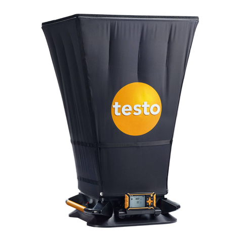
TESTO 400 User manual

testo 400 - Universal IAQ instrument
Instruction manual


Contents
Contents
1About this document ...........................................................................7
2Safety and disposal..............................................................................7
3Product-specific approvals .................................................................7
4Product-specific safety instructions ..................................................7
5Data protection .....................................................................................8
6Use.........................................................................................................8
7Product description .............................................................................9
7.1 Front view ............................................................................................................. 9
7.2 Rear view ............................................................................................................ 10
7.3 Probe connections .............................................................................................. 10
7.4 Probe overview ................................................................................................... 11
7.4.1 Compatible cable probes (digital)............................................................................... 11
7.4.2 Compatible Bluetooth®probes (digital)....................................................................... 11
7.4.3 Compatible NTC probes (analog)............................................................................... 12
7.4.4 Compatible Pt100 probes (digital) .............................................................................. 12
7.4.5 Compatible Smart Probes (digital) ............................................................................. 12
7.4.6 Compatible type K thermocouples (analog) ............................................................... 13
8Commissioning ..................................................................................14
8.1 Mains unit/energy storage unit............................................................................ 14
8.1.1 Charging the energy storage unit ............................................................................... 14
8.1.2 Rechargeable battery LED status .............................................................................. 16
8.1.3 Mains operation.......................................................................................................... 16
8.2 Switching the testo 400 on and off...................................................................... 16
8.3 Touchscreen ....................................................................................................... 18
8.4 Setup wizard ....................................................................................................... 18
8.4.1 Select language ......................................................................................................... 18
8.4.2 Country settings and units.......................................................................................... 19
8.4.3 WLAN......................................................................................................................... 19
8.4.4 Date and time............................................................................................................. 19
8.4.5 Contact information/company details ......................................................................... 19
8.4.6 Setting up an e-mail account...................................................................................... 20
8.5 Tutorial ................................................................................................................ 20
8.6 Connecting probes.............................................................................................. 20
8.6.1 Connecting a cable probe to the testo 400................................................................. 20
8.6.2 Connecting a Bluetooth®probe to the testo 400 ........................................................ 21
8.6.3 Probe update.............................................................................................................. 22

Contents
9Operation............................................................................................ 24
9.1 Display – user interface ...................................................................................... 24
9.2 Main menu .......................................................................................................... 25
9.3 Preparing for measurement................................................................................ 26
9.3.1 General measurement information ............................................................................. 26
9.3.2 Measuring mode......................................................................................................... 27
9.3.2.1 Punctual measurement ....................................................................................................... 27
9.3.2.2 Continuous measurement ................................................................................................... 29
9.4 Application menus .............................................................................................. 31
9.4.1 Basic view .................................................................................................................. 32
9.4.1.1 Graphic view ....................................................................................................................... 32
9.4.1.2 Table view........................................................................................................................... 33
9.4.2 Volume flow, duct ....................................................................................................... 33
9.4.3 Volume flow rate - grid measurement as per DIN EN 12599...................................... 36
9.4.4 Volume flow rate - grid measurement as per ASHRAE 111 ....................................... 40
9.4.5 Volume flow, outlet ..................................................................................................... 43
9.4.6 Volume flow - funnel................................................................................................... 44
9.4.7 Volume flow, Pitot tube............................................................................................... 46
9.4.8 Volume flow - k-factor................................................................................................. 49
9.4.9 Comfort level – PMV / PPD (EN 7730 / ASHRAE 55) ................................................ 51
9.4.10 Discomfort - draught rate............................................................................................ 55
9.4.11 Differential temperature (ΔT) ...................................................................................... 58
9.4.12 Differential pressure (ΔP) ........................................................................................... 60
9.5 Customer management ...................................................................................... 62
9.5.1 Creating and editing a customer................................................................................. 62
9.5.2 Creating and editing measuring sites ......................................................................... 63
9.5.2.1 Duct measuring site ............................................................................................................ 64
9.5.2.2 Outlet measuring site .......................................................................................................... 66
9.5.2.3 k-factor measuring site ........................................................................................................ 67
9.5.3 Searching for and managing customers and measuring sites .................................... 68
9.6 Measurement data management........................................................................ 70
9.6.1 Managing measurement data..................................................................................... 71
9.6.2 Editing measurement data.......................................................................................... 76
9.6.3 Searching for measurement data ............................................................................... 78

Contents
9.7 Sensor management........................................................................................... 80
9.7.1 General information about the probes........................................................................ 80
9.7.2 Calibration .................................................................................................................. 81
9.7.3 Surface increment ...................................................................................................... 82
9.7.4 Adjustment ................................................................................................................. 83
9.7.5 Damping..................................................................................................................... 85
9.7.6 Humidity calibration.................................................................................................... 86
10 Settings ...............................................................................................88
10.1 Carrying out a testo 400 update.......................................................................... 88
10.2 Setting up an e-mail account .............................................................................. 90
10.2.1 Setup via the wizard................................................................................................... 90
10.2.2 Manual set-up ............................................................................................................ 90
10.2.3 Deleting an e-mail account......................................................................................... 91
10.2.4 General information about the e-mail account............................................................ 91
10.3 Making basic settings.......................................................................................... 92
10.3.1 Regional settings........................................................................................................ 92
10.3.2 WLAN & e-mail........................................................................................................... 93
10.3.3 Measurement settings................................................................................................ 94
10.3.4 Company details ........................................................................................................ 95
10.3.5 Torch.......................................................................................................................... 95
10.3.6 Display settings .......................................................................................................... 96
10.3.7 Resetting the testo 400 to factory settings ................................................................. 97
10.4 General information ............................................................................................ 97
10.4.1 General instrument information .................................................................................. 97
10.4.2 Calling up the tutorial ................................................................................................. 98
10.4.3 Calling up the Quickstart Guide/detailed instructions ................................................. 98
10.4.4 Calling up legal information........................................................................................ 99
10.4.5 Other applications ...................................................................................................... 99
11 Maintenance .....................................................................................100
11.1 Rechargeable battery care................................................................................ 100
11.2 Notifications ...................................................................................................... 100
12 Technical data ..................................................................................101
13 testo DataControl PC software........................................................102
13.1 General information .......................................................................................... 102
13.2 Purpose............................................................................................................. 102
13.3 System requirements ........................................................................................ 103
13.4 Installing drivers and software .......................................................................... 103
Contents
13.5 Launching testo DataControl ............................................................................ 104
13.6 Connecting the testo 400.................................................................................. 104
13.7 Customer management .................................................................................... 107
13.7.1 Creating and editing customers and measuring sites............................................... 107
13.7.1.1 Customer .......................................................................................................................... 107
13.7.1.2 Measuring site................................................................................................................... 108
13.7.2 Search function ........................................................................................................ 111
13.7.3 Delete function ......................................................................................................... 112
13.8 Memory management....................................................................................... 113
13.8.1 Characteristics view.................................................................................................. 113
13.8.2 Graphic view............................................................................................................. 114
13.8.3 Table view ................................................................................................................ 117
13.8.4 Searching for and deleting measurement results ..................................................... 119
13.9 Settings............................................................................................................. 122
13.9.1 Help and Information ................................................................................................ 123
14 IAQ data logger ................................................................................ 124
14.1 IAQ data logger front view ................................................................................ 124
14.2 IAQ data logger rear view................................................................................. 125
14.3 Mains unit cable................................................................................................ 125
14.4 Switching the IAQ data logger on and off ......................................................... 126
14.5 IAQ data loggers – General information ........................................................... 126
14.6 Measuring with the IAQ data logger ................................................................. 127
14.6.1 General..................................................................................................................... 127
14.6.2 Carrying out a measurement with the IAQ data logger............................................. 128
14.7 Reading the IAQ data logger ............................................................................ 131
14.7.1 With testo 400 connected ......................................................................................... 132
14.7.2 With the testo 400 disconnected............................................................................... 133
14.8 LED status ........................................................................................................ 134
14.9 Technical data for IAQ data loggers ................................................................. 134
15 Questions and answers .................................................................. 135
15.1 Contact and support ......................................................................................... 136

1 About this document
7
1About this document
•The instruction manual is an integral part of the instrument.
•Keep this documentation to hand so that you can refer to it when necessary.
•Please read this instruction manual through carefully and familiarize yourself
with the product before putting it to use.
•Hand this instruction manual on to any subsequent users of the product.
•Pay particular attention to the safety instructions and warning advice in order
to prevent injury and damage to the product.
2Safety and disposal
Take the testo information document into account (accompanies the product).
3Product-specific approvals
You can find the current country approvals in the Approval and Certification
document (enclosed with the product).
4Product-specific safety instructions
DANGER
Integrated magnet
Danger to life for persons with pacemakers!
-Keep a distance of at least 20 cm between your pacemaker and the
measuring instrument.
ATTENTION
Integrated magnet
Damage to other devices!
-Keep a safe distance from devices that may be damaged by magnetism
(e.g. monitors, computers, credit cards, memory cards, etc.).

5Data protection
8
5Data protection
The testo 400 measuring instrument makes it possible to input and store
personal data such as name, company, customer number, address, telephone
number, e-mail address and homepage.
Please be aware that your use of the functions offered here is entirely your own
responsibility. This applies in particular to use of the interactive functions (e.g.
storing customer data or sharing readings). You are responsible for compliance
with the data protection regulations and laws applicable in your country.
Therefore it is your responsibility to ensure the legality of the processing of
personal data for which you are responsible.
The personal data collected with the measuring instrument is never
automatically transferred to Testo SE & Co. KGaA.
You can find the detailed Privacy Policy – Measuring Instruments in the testo
400 Help & Information main menu in the form of a PDF under Exclusion of
liability -> Data protection information.
6Use
The testo 400 is an instrument for measuring climate-related parameters. The
testo 400 is particularly suitable for carrying out comfort level measurements for
workplace evaluation and flow measurements in and on air conditioning
systems.
The instrument is only to be used by qualified expert personnel. The
product must not be used in potentially explosive atmospheres!

7 Product description
9
7Product description
7.1 Front view
1
On/Off and Standby button
2
User interface/Touchscreen (see
Section 9.1)
3
Front camera
4
Connections for probes (see
Section 7.3)

7Product description
10
7.2 Rear view
1
Camera 2
Differential pressure
measurement connections
(+/- marking)
3
Magnets
4
Attachment point for carrying
strap
5
USB port/mains connection
CAUTION
Make sure the pressure tube does not jump away from the connection
socket.
Risk of injury!
-Ensure correct connection.
7.3 Probe connections

7 Product description
11
1
Thermocouple probe type K
connection (T1 and T2)
2
Connection for probes with
TUC connector (A and B)
7.4 Probe overview
7.4.1 Compatible cable probes (digital)
Description Order no.
Hot wire probe, fixed cable, including temperature
sensor
0635 1032
Hot wire probe, fixed cable, including temperature and
humidity sensor
0635 1572
Vane probe (Ø 16 mm), fixed cable
0635 9532
Vane probe (Ø 16 mm), fixed cable, including
temperature sensor
0635 9572
Fume cupboard probe, fixed cable
0635 1052
Vane probe (Ø 100 mm), fixed cable, including
temperature sensor
0635 9432
High-precision vane probe (Ø 100 mm), fixed cable,
including temperature sensor
0635 9372
Humidity/temperature probe, fixed cable
0636 9732
High-precision humidity/temperature probe, fixed cable
0636 9772
Robust humidity/temperature probe for temperatures up
to +180 °C, fixed cable
0636 9775
Turbulence probe, fixed cable
0628 0152
Lux probe, fixed cable
0635 0551
CO
2
probe including temperature and humidity sensor,
fixed cable
0632 1552
CO probe, fixed cable
0632 1272
7.4.2 Compatible Bluetooth®probes (digital)
Description Order no.
Hot wire probe with Bluetooth®, including temperature
and humidity sensor
0635 1571
Vane probe (Ø 16 mm) with Bluetooth®, including
temperature sensor
0635 9571
Vane probe (Ø 100 mm) with Bluetooth®, including
temperature sensor
0635 9431
High-precision vane probe (Ø 100 mm) with Bluetooth®,
including temperature sensor
0635 9371
Temperature/humidity probe with Bluetooth
®
0636 9731

7Product description
12
Description Order no.
High-precision temperature/humidity probe with
Bluetooth
®
0636 9771
CO
2
probe with Bluetooth®, including temperature and
humidity sensor
0632 1552
CO probe with Bluetooth®
0632 1272
7.4.3 Compatible NTC probes (analog)
Description Order no.
Waterproof immersion/penetration probe – with NTC
temperature sensor
0615 1212
Robust air probe – with NTC temperature sensor
0615 1712
Temperature probe with Velcro and NTC temperature
sensor
0615 4611
Clamp probe with NTC temperature sensor – for
measurements on pipes (Ø 6-35 mm)
0615 5505
Pipe wrap probe with NTC temperature sensor – for
measurements on pipes (Ø 5-65 mm)
0615 5605
7.4.4 Compatible Pt100 probes (digital)
Description Order no.
High-precision immersion/penetration probe with Pt100
temperature sensor
0618 0275
Immersion/penetration probe with Pt100 temperature
sensor
0618 0073
Air temperature probe with Pt100 temperature sensor
0618 0072
Flexible immersion probe with Pt100 temperature sensor
and flexible PTFE probe tube
0618 0071
Laboratory probe with Pt100 temperature sensor in
glass tube (Duran 50), resistant to aggressive media
0618 7072
7.4.5 Compatible Smart Probes (digital)
Description Order no.
testo 115i - clamp thermometer operated by smartphone
0560 1115
0560 2115 02
0560 2115 03 (US)
testo 805i - infrared thermometer operated by
smartphone
0560 1805

7 Product description
13
Description Order no.
testo 605i - thermohygrometer operated by smartphone
0560 1605
0560 2605 02
0560 2605 03 (US)
testo 405i - thermal anemometer operated by
smartphone
0560 1405
testo 410i - vane anemometer operated by smartphone
0560 1410
testo 510i - differential pressure measuring instrument
operated by smartphone
0560 1510
testo 549i - high-pressure measuring instrument
operated by smartphone
0560 1549
0560 2549 02
0560 2549 03 (US)
7.4.6 Compatible type K thermocouples (analog)
Description Order no.
Surface paddle probe
0602 0193
TC measuring tip for radio probes
0602 0293
Surface probe
0602 0393
TC surface tip for radio probes
0602 0394
Flexible immersion measuring tip, TC type K
0602 0493
Immersion probe
0602 0593
TE couple with TC plug TC type K
0602 0644
TE couple with TC plug TC type K
0602 0645
TE couple PTFE with TC plug TC type K
0602 0646
Surface probe
0602 0693
Globe probe Ø 150mm
0602 0743
Surface probe
0602 0993
Immersion/penetration probe, waterproof
0602 1293
Air probe, robust
0602 1793
Surface probe
0602 1993
Surface temperature probe TC type K
0602 2394
Immersion/penetration probe
0602 2693
Pipe wrap probe TC type K
0602 4592
Clamp probe with thermoelectric couple.
0602 4692
Magnetic probe
0602 4792
Magnetic probe Tmax 400°C
0602 4892
Plug-in immersion measuring tip, flexible
0602 5693
Measuring tip with TC plug TC type K
0602 5792
Measuring tip with TC plug Type K, class 3
0602 5793
Pipe wrap probe with Velcro strip
0628 0020

8Commissioning
14
Description Order no.
Penetration probe type K
0628 0026
Penetration temperature probe
0628 1292
Surface probe
0628 9992
8Commissioning
8.1 Mains unit/energy storage unit
The measuring instrument is supplied with an energy storage unit.
Fully charge the energy storage unit before using the measuring
instrument.
Plug the mains unit USB cable into the USB port on the side.
If the mains unit is connected, the measuring instrument is
automatically powered via the mains unit.
Only charge the energy storage unit at an ambient temperature of 0 to
45 °C.
8.1.1 Charging the energy storage unit
1
Connect the USB mains unit to the USB interface/mains unit socket of
the testo 400 (see Section 7.2).
2
Connect the mains plug of the mains unit to a mains socket.
The charging process starts.
If the energy storage unit has completely discharged, the charging time
at room temperature is approx. 5-6 hours. Only charge the instrument
at an ambient temperature of 0 to 45 °C.
If the battery level is 6 – 10%, this message is displayed: “Once the
battery level reaches 5%, the measuring instrument undergoes a
controlled shut-
down. Please charge up your measuring instrument in a
timely manner.”
If the battery level is 5% or less, the following message is displayed:
“The battery level is very low. The measuring instrument will now shut

8 Commissioning
15
down.” The instrument should only be switched back on after a brief
charging phase. The minimum battery level must be 6%.

8Commissioning
16
8.1.2 Rechargeable battery LED status
LED status Description
Lit up green Instrument is supplied with power
(battery fully charged)
Flashing green (rapidly) Instrument is on and being supplied
with power (battery is charging)
Flashing green (slowly)
Ready for operation in battery mode
Flashing green/red
Instrument is off and being supplied
with power (battery is charging)
Flashing red
Internal error, please restart. If the
error has still not been rectified,
please carry out a factory reset (see
Section 10.3.7). If the problem
persists, contact Testo Customer
Service.
8.1.3 Mains operation
1
Connect the USB mains unit to the USB interface/mains unit socket of
the testo 400 (see Section 7.2).
2
Connect the mains plug of the mains unit to a mains socket.
The measuring instrument is powered via the mains unit. The battery
charges.
8.2 Switching the testo 400 on and off
Current
status
Action Function
Instrument off
Press and hold down the
button (> 3 sec)
Instrument is switched on

8 Commissioning
17
Current
status
Action Function
When the measuring instrument is started for the first time, the setup
wizard guides you through the following setting parameters step by
step:
- Language
- Country
- Units
- WLAN
- Date and time
- Own company address
- E-mail account
After the setup wizard, a tutorial can be launched. The tutorial
demonstrates the general o
peration and the most important functions of
the measuring instrument using examples.
Instrument on
Press the button briefly
(< 1 sec)
Instrument is switched to
standby mode. The instrument
is re-activated when the button
is pressed again.
Instrument on
Press and hold down the
button (> 1 sec)
Choice: press [OK] to switch the
instrument off or press [Cancel]
to cancel switch-off of the
instrument.
The tutorial can be executed again at any time in the main menu under
Help and Information.
Measuring values that have not been saved are lost when the
measuring instrument is switched off.

8Commissioning
18
8.3 Touchscreen
You only need three touchscreen movements to use the testo 400:
Description
Tapping
To open applications, select menu icons, press
buttons on the display or enter characters with the
keypad, tap these with a finger in each case.
Swiping
Swipe to the right or left on the display to show
further views, e.g. to switch from the list view to the
graphic view.
Zooming
In order to make a section of the display larger or
smaller, touch the display with two fingers and
move them apart or together.
8.4 Setup wizard
When the testo 400 is started up for the first time, the setup wizard is activated
and guides you step-by-step through the following setting parameters.
The instrument setup that is implemented can be adapted at any time in
the Settings menu.
8.4.1 Select language
The first step is to select the language for using the testo 400.

8 Commissioning
19
8.4.2 Country settings and units
In this step, you have the option of selecting the country and of deciding whether
you want to use the metric or imperial unit system. It is also possible to establish
user-defined settings for the units. See Section 10.3.1 and 10.3.3.
8.4.3 WLAN
Click on the WLAN field to connect the testo 400 to the internet. Here,
connection to a known WLAN must be established. The icon at top right
allows you to manually add networks, call up saved networks and update
available networks. In addition, further adjustments can be made via Advanced.
For password-protected networks, you need to enter the password. On
secured networks, various ports may be blocked, restricting the creation
of e-mail accounts and the sending/receiving of e-mails.
The WLAN connection can be used for various functions:
•Automatic notification of information for updates
•Carrying out updates of the instrument firmware (see Section 10.1)
•Sending measurement reports as PDF files and measurement data as .json
and .csv files via e-mail (see Section 9.6)
•Using the internet browser via the Other applications menu (see Section
10.4.5)
If the WLAN reception is not sufficient, the error message Network
disabled appears. Try connecting the testo 400 to a better WLAN
network.
8.4.4 Date and time
Click on the Time field to set the date and time. It is possible to automatically
retrieve the date/time via network or GPS or to set it manually. The time zone
can also be set automatically/manually and you can choose between 12-
hour/24-hour mode.
We recommend that you select Use network-provided time as the setting.
Please also see Section 10.3.1.
8.4.5 Contact information/company details
On each line, personal details can be entered for the items Company /
Technician name / Street, building number / Postcode, city / Country /
Telephone / Fax / E-mail and Homepage. In principle, company details can also
be inserted using the testo DataControl software. The company details will be
displayed in all PDF reports at the top right of the document and also listed in
the measurement data report. The company details stored in the testo 400 at
the time of the measurement cannot be subsequently changed in the PDF report

8Commissioning
20
of the measurement. The new company details will only be stored in the PDF
report once a new measurement is carried out. Please also see Section 10.3.4.
8.4.6 Setting up an e-mail account
Click on the E-mail field to connect an e-mail account to the testo 400
measuring instrument, so that you can send measurement data reports via e-
mail. See also Section 10.2.
8.5 Tutorial
At the end of the Setup wizard, the tutorial can be launched.
The tutorial can be executed again at any time via the Help and
Information menu.
The tutorial demonstrates the general operation and the most important
functions of the measuring instrument, using brief examples. The detailed
descriptions can be found in the relevant sections.
•Connect cable and Bluetooth®probes (see Section 8.6)
•Display - user interface (see Section 9.1)
•Application menus (see Section 9.4)
•General measurement information (see Section 9.3.1)
•Managing measurement data (see Section 9.6.1)
•Customer management (see Section 9.5)
•Sensor management (see Section 9.7)
•Setting up an e-mail account (see Section 10.2)
8.6 Connecting probes
All probes can be connected or changed while the instrument is
switched on. However, the connection must not be interrupted during a
probe update.
8.6.1 Connecting a cable probe to the testo 400
>
Connect the testo 400 to the probe via the TUC slot.
The cable probe is immediately displayed in the sensor management,
in the basic view and in the relevant measurement menu.
Other manuals for 400
4
Table of contents
Other TESTO Measuring Instrument manuals

TESTO
TESTO 0699 6446 Series User manual

TESTO
TESTO Saveris User manual

TESTO
TESTO 608 - H1 User manual

TESTO
TESTO Smart Probes 510i User manual

TESTO
TESTO 310 II User manual

TESTO
TESTO 816 User manual

TESTO
TESTO 417 User manual

TESTO
TESTO 420 Installation manual

TESTO
TESTO 440 User manual

TESTO
TESTO 510 User manual
Popular Measuring Instrument manuals by other brands

ICS Schneider Messtechnik
ICS Schneider Messtechnik Snap 41 Instruction Manual and Safety Information

Keithley
Keithley 6487 user manual

agratronix
agratronix 07125 Operator's manual

DIGITIZE
DIGITIZE System 3505 Installation & operation manual

Rycom
Rycom 8879 user manual

Bushnell
Bushnell 20-2018 instruction manual