TESTO 327 User manual

Instruction manual en
testo 327
Flue gas analyser, country-specific version GB

Safety and the environment 3
Safety and the environment
About this document
Please read this documentation through carefully and familiarise yourself with
the product before putting it to use. Keep this documentation to hand so
that you can refer to it when necessary. Hand this documentation on to any
subsequent users of the product.
Pay particular attention to information emphasised by the following symbols:
· With the signal word Warning!:
Warns against hazards which could result in serious physical injury if
the precautionary measures indicated are not taken.
· With the signal word Caution!:
Warns against hazards which could result in minor physical injury or
damage to equipment if the precautionary measures indicated are
not taken.
· Additional information.
Avoiding personal injury/damage to equipment
o not make measurements with the measuring instrument and its sensors
on or near live components unless the instrument is expressly approved for
current/voltage measurements!
Never store the measuring instrument together with solvents and do not use
any desiccants.
Only operate the measuring instrument properly, for its intended purpose
and within the parameters specified in the technical data. o not use force.
Only carry out the maintenance and repair work that is described in the
documentation. Follow the prescribed steps exactly. Only use original spare
parts from Testo.
Any additional work must only be carried out by authorised personnel.
Testo will otherwise refuse to accept responsibility for the proper functioning
of the measuring instrument after repair and for the validity of certifications.
Temperatures given on probes/sensors relate only to the measuring range of
the sensors. o not expose handles and feed lines to any temperatures in
excess of 70 °C unless they are expressly permitted for higher temperatures.
de
en
fr
esit
pt
sv
nl
????
Contents2
Contents
Contents ................................................................................................2
Safety and the environment ....................................................................3
EC declaration of conformity ..................................................................7
Product description ................................................................................8
First steps ..............................................................................................9
Using the product ..................................................................................12
Preparing for measurement ....................................................................12
Performing the measurement ..................................................................14
Checking the instrument ........................................................................18
Maintaining the product ........................................................................19
Tips and assistance ..............................................................................22
Accessories and spare parts ................................................................24
Appendix ..............................................................................................25

Specifications 5
de
en
fr
esit
pt
sv
nl
????
Specifications4
Products with BluetoothÒ(Option)
Changes or modifications, which are not expressly approved by the responsible
official body, can lead to a withdrawal of operating permission.
Interference with data transfer can be caused by instruments which transmit on
the same ISM band, e.g. microwave ovens, ECT telephony, non-secure
software in cellphones when telephoning, transmitting/receiving text messages
etc.
The use of radio connections is not allowed in e.g. aeroplanes and hospitals.
For this reason, the following point must be checked before entering:
eactivate Bluetooth function
MMaaiinn mmeennuuee -- SSeettttiinnggss -- BBuueettooootthh -- ddeeaaccttiivvaattee BBlluueettooootthh ((OOffff))
Protecting the environment
Take faulty rechargeable batteries/spent batteries to the collection points
provided for them.
Send the product back to Testo at the end of its useful life. We will ensure
that it is disposed of in an environmentally friendly manner.
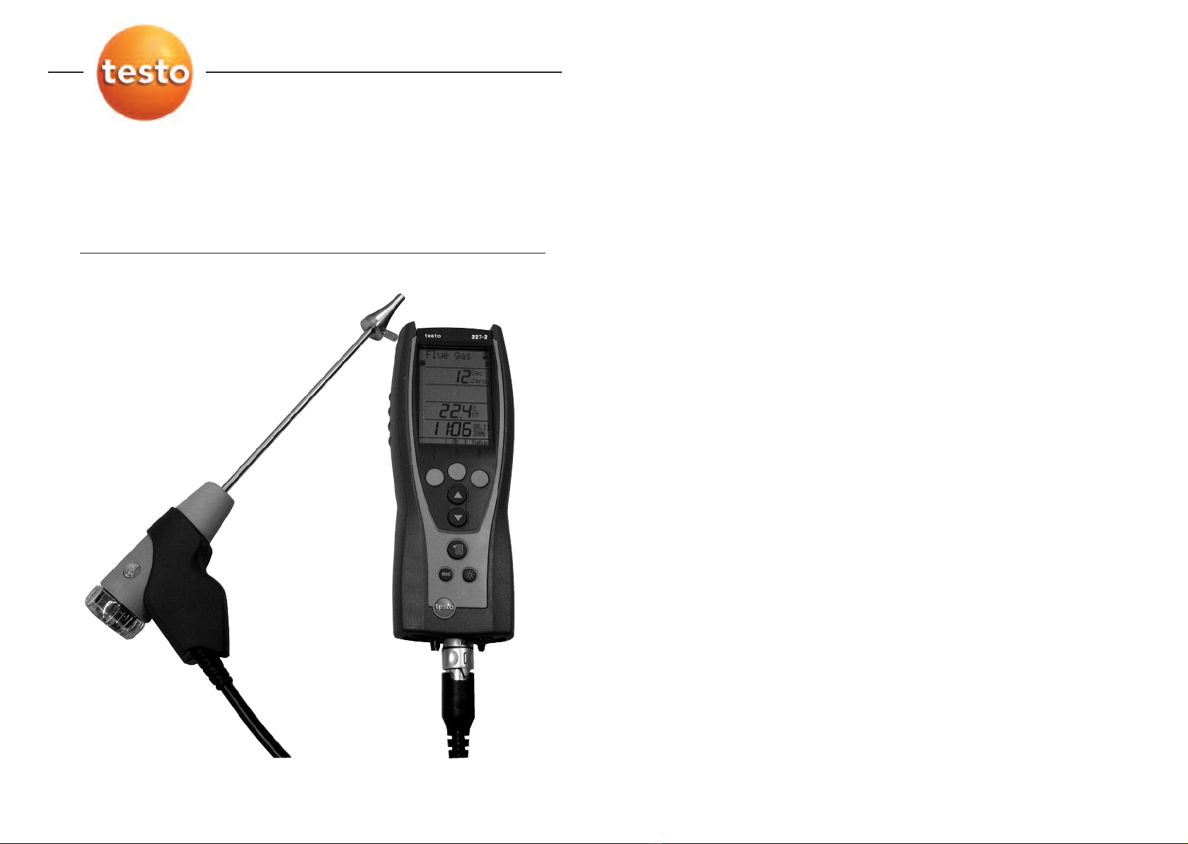
Specifications
Functions and use
The testo 327 is a hand-held measuring instrument for the professional flue gas
analysis of domestic and light commercial gas and oil boilers and appliances.
This includes condensing boilers and gas heaters. The unit is designed to carry
out tests shown in BS 7967, and has a timed tightness test, let by test and a
timed CO function.
These systems can be adjusted using the testo 327 and checked for
compliance with the applicable limit values.
The testo 327 is available in four versions; the scope of function varies
according to the version:
· testo 327 O2: Infrared interface
· testo 327 CO: Infrared interface
· testo 327-1 (O2, CO): Infrared interface
· testo 327-2 (O2, CO): Infrared / IR A interface, memory, automatic
sensor diagnosis, option: Bluetooth (data
interface)
Warning The testo 327 must not be used in areas at risk of explosion,
for long-term measurements or as a safety (alarm) device!
The testo 327 with the Bluetooth option may only be operated in countries in
which it is type approved (see Technical ata).
Technical data
iissppllaayy vvaarriiaabblleess [[uunniittss]]MMeeaassuurriinngg rraannggee//rreessoolluuttiioonnAAccccuurraaccyy//rreessppoonnssee ttiimmee 11))
OOxxyyggeenn,, vviiaa iinntteerrnnaall eelleeccttrroo--cchheemmiiccaall sseennssoorr ((nnoott 332277 CCOO))::
OO22content [%],
OO22aaiirrsupply [%],
Reference value OO22rreeff[%]0...21% / 0.1% ±0.2% / t90 <40s
CCaarrbboonn mmoonnooxxiiddee,, 332277--11::
CCOOcontent [ppm, mg/m³] 0...4,000ppm / 1ppm ±20ppm (0...400ppm), ±5% of reading
(401...1,000ppm),
(H2share <10%) ±10% of reading (1,001...4,000ppm) / t90 <60s
CCaarrbboonn mmoonnooxxiiddee,, vviiaa iinntteerrnnaall eelleeccttrroo--cchheemmiiccaall sseennssoorr ((oonnllyy 332277--22 wwiitthh ooppttiioonn CCOOHH22))::
CCOO content [ppm, mg/m³] 0...8,000ppm / 1ppm ±20ppm (0...200ppm), ±5% v. Mw. (201...2,000ppm),
±10% of reading (2001...8,000ppm) / t90 <40s
AAmmbbiieenntt CCaarrbboonn mmoonnooxxiiddee,, vviiaa iinntteerrnnaall eelleeccttrroo--cchheemmiiccaall sseennssoorr::
AAmmbbiieenntt CCOOcontent
aammCCOO[ppm] 0...2,000ppm / 1ppm ±10ppm (0...100ppm), ±10% of reading (>100ppm) /
t90 <40s
TTeemmppeerraattuurree,, vviiaa ttyyppee KK tthheerrmmooccoouuppllee ooff fflluuee ggaass pprroobbee ((NNiiCCrr--NNii))::
Flue gas temperature FFTT,
Flue gas dew point AATTPP,
Ambient air AATT-40...+600°C / 0.1°C, ±0.5°C (-40...100°C), ±0.5% of reading (>100°C),
-40...1,112°F / 0.1°F ±0.9°F (-40...212°F), ±0.5% of reading (>212°F) /
t98 <50s (TE 0.5mm); <100s (TE 1mm)
TTeemmppeerraattuurree,, vviiaa ddiiffffeerreennttiiaall tteemmppeerraattuurree sseett 0055554411220088::
Flue gas socket T1 [°C, °F],
Sensor socket T2 [°C, °F] -40...+600°C / 0.1°C, ±0.5°C (-40...100°C), ±0.5% of reading (>100°C),
-40...1,112°F / 0.1°F ±0.9°F (-40...212°F), ±0.5% of reading (>212°F) /
t98 <50s (TE 0.5mm); <100s (TE 1mm)
PPrreessssuurree,, vviiaa iinntteerrnnaall ddiiffffeerreennttiiaall pprreessssuurree sseennssoorr::
Flue draught rrgghhtt[mbar,
hPa, inW, in Hg] -40...40hPa / 0.01hPa ±0.02hPa (-0.50...0.60hPa), ±0.03hPa
(0.61...3hPa), ±1.5% of reading (>3hPa) / -
Flue draught rrgghhtt, with option
of precision draught [Pa] -100...100Pa / 0.1Pa ±3Pa / -
PPrreessssuurree aanndd ttiigghhttnneessss tteesstt vviiaa iinntteerrnnaall ddiiffffeerreennttiiaall pprreessssuurree sseennssoorr,, wwiitthh ddiiffffeerreennttiiaall pprreessssuurree sseett
0055554411220033::
ifferential pressure
∆∆pp[hPa] -200...200hPa / 0.1hPa ±0.5hPa (0.0...50.0hPa)
(with option precision ±1% of reading (50.1...100.0hPa)
difference pressure: 0.01hPa) ±1.5% of reading (100.1...200.0hPa)
EEffffiicciieennccyy,, ccaallccuullaatteedd::
Efficiency ηη2[%],
Efficiency ηη++3) [%] 0...120% / 0.1% ±0.2% / -

EC conformity declaration 7
de
en
fr
esit
pt
sv
nl
????
Specifications 6
EC declaration of conformity
i
is
sp
pl
la
ay
y
v
va
ar
ri
ia
ab
bl
le
es
s
[
[u
un
ni
it
ts
s]
]M
Me
ea
as
su
ur
ri
in
ng
g
r
ra
an
ng
ge
e/
/r
re
es
so
ol
lu
ut
ti
io
on
nA
Ac
cc
cu
ur
ra
ac
cy
y/
/r
re
es
sp
po
on
ns
se
e
t
ti
im
me
e
1
1)
)
F
Fl
lu
ue
e
g
ga
as
s
l
lo
os
ss
s,
,
c
ca
al
lc
cu
ul
la
at
te
ed
d
Flue gas loss qqAA2) [%], 0...99.9% / 0.1% - / -
Flue gas loss qqAA++3) [%], -20.0...99.9 / 0.1% - / -
A
Ai
ir
r
r
ra
at
ti
io
o
(
(n
no
ot
t
3
32
27
7
C
CO
O)
)
Air ratio λλ[-] 1...20 / 0.01 - / -
CCaarrbboonn ddiiooxxiiddee
CCOO22content [%] 0...CO2max / 0.01% - / -
1) Recommended minimum duration of measurement to guarantee correct readings: 3min, 2) Calorific value range not taken into
account,
3) Calorific value range taken into account
CCaallccuullaattiioonn ffoorrmmuullaaee ffoorr ccaallccuullaatteedd ddiissppllaayy vvaarriiaabblleess
· See Appendix
FFuueellss
· Quantity: 5
· esignation/fuel parameters: See Appendix
AAmmbbiieenntt ccoonnddiittiioonnss
· Operating temperature: -5...45°C/ 23...113°F
· Storage temperature for measuring
instrument:
-20...50°C/ -4...122°F,
Li-ion rechargeable battery: 0...35°C/
32...95°F
HHoouussiinngg
· Material: ABS/ PA/ TPU
· imensions: 240 x 90 x 58mm
· Weight: Approx. 620g
· Protection class: IP40
VVoollttaaggee ssuuppppllyy
· Current source: Li-ion rechargeable battery
3.7 V/1.4 Ah (0515 0114) / 3.7 V/2.4 Ah
(0515 0100), mains unit 6.3V/1.2A
· Battery life (measuring gas pump on, display
light off): Approx. 4 h (0515 0114) / approx.
10h (0515 0100)
· Battery charge time: Approx. 5-6 h
iissppllaayy
· Type: Illuminated LC
· Updating of readings: 1/s
iirreeccttiivveess,, ssttaannddaarrddss aanndd tteessttss
· EC irective: 2004/108/EEC
· Tests: EN 50379, Part 2 (O2, °C, hPa),
Part 3 (CO), testo 327-2 with
option COH2 additionally:
EN 50379, Part 2 (CO)
CO accuracy: independantly
tested to BS7967
WWaarrrraannttyy
· Measuring instrument, flue gas probe: 24
months
· Measuring cells: 24 months
· Thermocouple: 12 months
· Rech. batt.: 12 months
OOppttiioonn BBlluueettooootthh ((tteessttoo 332277--22 oonnllyy))
· Type-designation: BlueNiceCom IV
· Bluetooth Qualified Product Notice:
BNC4_HW2x_SW2xx
· Bluetooth listing identifier: B013784
· Bluetooth listing company: 10274
Range <10m
Option Bluetooth Certification
EEUU ccoouunnttrriieess
Belgium (BE), Bulgaria (BG), enmark ( K),
Germany ( E), Estonia (EE), Finland (FI), France
(FR), Greece (GR), Ireland (IE), Italy (IT), Latvia
(LV), Lithuania (LT), Luxembourg (LU), Malta
(MT), Netherlands (NL), Austria (AT), Poland
(PL), Portugal (PT), Romania (RO), Sweden
(SE), Slovakia (SK), Slovenia (SI), Spain (ES),
Czech Republic (CZ), Hungary (HU), United
Kingdom (GB) and Republic of Cyprus (CY).
OOtthheerr EEFFTTAA CCoouunnttrriieess
Iceland, Liechtentein, Norway and Switzerland
NNoonn--eeuurrooppeeaann ccoouunnttrriieess
Japan, Columbia, Turkey

First steps 9
At a glance: Flue gas probe
Removable filter chamber with
window and particle filter
Probe handle
Connecting cable
Connector for measuring
instrument
First steps
Charging rechargeable battery
Charge the rechargeable battery fully before using the measuring instrument.
The rechargeable battery can only be charged at an ambient temperature of
0...+35 °C. If the rechargeable battery pack has discharged completely, the
charging time at room temperature is approx. 5-6 hrs.
CChhaarrggiinngg tthhee rreecchhaarrggeeaabbllee bbaatttteerryy iinn tthhee mmeeaassuurriinngg iinnssttrruummeenntt::
The measuring instrument must be switched off.
11Connect the plug of the mains unit to the mains unit socket on the
measuring instrument.
22Connect the mains plug of the mains unit to a mains socket.
- The charging process will start. The charge status will be shown on the
display. The charging process will stop automatically when the
rechargeable battery is fully charged.
CChhaarrggiinngg tthhee rreecchhaarrggeeaabbllee bbaatttteerryy iinn cchhaarrggeerr 00555544 11008877 ((aacccceessssoorryy))::
Refer to the documentation that comes with the charger.
de
en
fr
esit
pt
sv
nl
????
Product description8
Product description
At a glance: Measuring instrument
Head: IR interface (327-2: IR A) for
connection to Testo protocol
printers, ON/OFF switch ( ),
condensate outlet.
CCaauuttiioonn!!Risk of injury from
infrared beam!
o not point infrared beam at
people's eyes!
isplay.
iissppllaayy ssyymmbboollss
: Battery capacity( : full, : empty)
: Print function: sends data
Control keys
KKeeyy ffuunnccttiioonnss
: Function keys (3x): shows relevant
function on the display.
: Up/down keys: changes display view.
: Light key: switches display light on/off.
: Menu key.
: Cancel key.
Sensor socket for TC temperature probe, flue gas socket for flue gas probe,
gas outlet, mains socket
Sides: window of condensate trap with fill level display
Rear: service compartment (battery, measuring cells)
Rear: magnets for fixing measuring instrument to metallic surfaces.
WWaarrnniinngg!!Strong magnets can cause damage!
Keep well away from products which could be damaged through the
effects of magnetism (e.g. pacemakers, monitors, computers, credit
cards).
Rear: eyelet for attaching a carrying strap (accessory).

First steps 11
de
en
fr
esit
pt
sv
nl
????
First steps10
33Select the required function using / and confirm entry with the OOKK
function key.
F
Fu
un
nc
ct
ti
io
on
ns
s
11..iissppll.. sseeqq: selects parameters and units of measurement and assigns a position number
for the
display/protocol printouts.
22..aattee//TTiimmee: sets the date and time
33..LLaanngguuaaggee: sets the language.
44..PPrriinntteerr: sets the printer to be used.
- The selected function is opened and the position number
(iissppll.. sseeqq function only) or parameter which can be set flashes.
55..BBlluueettooootthh (327-2 with option Bluetooth only): activate/ deactivate interface.
44Set the position number ( iissppll.. sseeqq function only)/parameter:
For iissppll.. sseeqq function only: Select the position number to be changed
using / and confirm with the CChhaannggeefunction key.
Alternatively: elete the position number with eell..and insert a new
position number using IInnss...
iissppll.. sseeqq function: Only parameters and units of measurement which are
assigned to a position number appear in the display and on printouts.
A maximum of 20 position numbers can be activated.
KKeeyy ffuunnccttiioonnss
· : Change parameters.
· For aattee// TTiimmee function: changes between hours, minutes, day, month and year.
· For iissppll.. sseeqq function: changes between parameter and unit of measurement (only
available if there are several units of measurement for the selected parameter).
·OOKKfor iissppll.. sseeqqfunction and a flashing position number: confirms setting and moves to
next display position.
·OOKKfor iissppll.. sseeqqand FFiinniisshhflashing: confirms settings and leaves the function.
·OOKKfor aattee// TTiimmee, LLaanngguuaaggee, and PPrriinntteerr: functions: confirms setting and leaves the
function.
·eesscc: leaves the parameter or function without applying the changes.
EExxaammppllee:: ""CChhaannggee ddiissppllaayy ppoossiittiioonn""
The position number to be changed has been selected.
1 Press / several times until the required parameter flashes.
2 Press the or function key to go to the menu for selecting the unit of measurement.
3 Press / several times until the required unit of measurement flashes.
4 Press the OOKKfunction key to confirm the setting and move to the next display position.
5 At the end of performing the settings: Press / several times until FFiinniisshhflashes
(appears after the last position number) and confirm entry with OOKK.
Operation with the mains unit
If the mains unit is connected, the measuring instrument is automatically
powered from the mains unit. It is not possible to charge the rechargeable
battery in the measuring instrument during operation.
11Connect the plug of the mains unit to the mains unit socket on the
measuring instrument.
22Connect the mains plug of the mains unit to a mains socket.
- The measuring instrument is powered via the mains unit.
- If the instrument is switched off and a rechargeable battery is inserted,
the charging process will start automatically. Switching the measuring
instrument on has the effect of stopping rechargeable battery charging
and the measuring instrument is then powered via the mains unit.
Switching on/off
SSwwiittcchhiinngg tthhee iinnssttrruummeenntt oonn::
Press .
- Initialisation phase:
· All display segments are lit (length of time: 3 s).
· Serial number, firmware version, instrument designation, date, time
and country-specific version of instrument are displayed (length of
time: 5 s).
- The MMeeaassuurreeflue gas option is displayed.
SSwwiittcchhiinngg tthhee iinnssttrruummeenntt ooffff::
Press .
- sometimes: The pump starts and the measuring cells are rinsed until the
switch-off thresholds (O2>20 %, other parameters 50 ppm) are reached.
Rinsing lasts no more than 2 minutes.
Performing instrument settings
PPeerrffoorrmmiinngg sseettttiinnggss::
11Press .
22Select SSeettttiinnggssusing / and confirm entry with the OOKKfunction key.

Using the product 13
AAlliiggnniinngg tthhee fflluuee ggaass pprroobbee::
The flue gas must be able to flow freely past the thermocouple.
Align the probe by turning it as required.
The tip of the probe must be in the centre of the flue gas flow.
Align the flue gas probe in the flue gas duct
so that the tip is in the centre of the flow
(area of the highest flue gas temperature).
Activating the required functions
SSwwiittcchhiinngg tthhee iinnssttrruummeenntt oonn::
Press .
AAccttiivvaattiinngg ffuueell::
11Press .
22Select FFuueellusing / and confirm entry with the OOKKfunction key.
33Select the fuel to be measured using / and confirm entry with the
OOKKfunction key.
RGS
de
en
fr
esit
pt
sv
nl
????
Using the product12
sing the product
Preparing for measurement
Connecting probes/sensors
The instrument needs to detect which probes or sensors are connected, before
switch on. If you fail to do this simply turn off instrument connect probe and
re-start unit.
CCoonnnneeccttiinngg tthhee pprroobbeess::
Insert the connector into the flue gas
socket and lock by turning it clockwise
gently (bayonet lock).
There must be no more than one extension
lead (0554 1201) between the measuring
instrument and the flue gas probe.
CCoonnnneeccttiinngg tthhee sseennssoorr::
If no ambient air temperature sensor is connected, the temperature
measured by the thermocouple of the flue gas probe during the zeroing
phase is used as the ambient air temperature. All dependent parameters
are calculated using this value. This method of measuring ambient air
temperature is sufficient for systems dependent on ambient air. However,
ensure that the flue gas probe is near the intake duct of the burner during
the zeroing phase.
If an ambient air temperature sensor is connected, the ambient air
temperature is measured continuously by this sensor.
Insert the connector of the sensor into the sensor socket.
sing the flue gas probe
CChheecckkiinngg tthhee tthheerrmmooccoouuppllee::
The thermocouple of the flue gas probe must not lie against the probe cage.
Check before use. Bend the thermocouple
back if necessary.

Using the product 15
de
en
fr
esit
pt
sv
nl
????
Using the product14
not be pressurised during zeroing!
To help position the flue gas probe in the centre of the flow (area of the
highest flue gas temperature), the flue gas temperature measured is
shown graphically.
o not measure for longer than 5 minutes, as the readings may fall
outside of the tolerances due to a possible drift of the pressure sensor.
SSmmookkee//OOiillddfunction: Only available if a liquid fuel has been activated.
iiffff--tteemmpp.. function: The differential temperature set (0554 1208)
must be connected. The ambient air sensor must be unplugged (located
bottom left of unit) before connecting the T1 sensor. Be aware that the
connector is a firm fit, when disconnecting.
The differential temperature is calculated from T1 - T2.
iiffff--pprreessss function: The gas pressure set (0554 1203) must be connected.
The pressure sensors are zeroed when the iiffff..--pprreessssfunction is started
(length of time: 5 s). The measuring instrument must not be pressurised
during zeroing!
o not measure for longer than 5 min, as a drift of the pressure sensor
may result in readings outside the tolerance limits.
AAmmbbiieennttCCOO: When the measuring cells are first started after the
measuring instrument is switched on, they are zeroed (length of time: 30
s). Exception: The FFlluuee ggaassfunction has already been called up.
Any connected probe must be in the open air during the zeroing phase!
The measurement values from the functions rraauugghhtt,, iiffff..--tteemmpp..,
iiffff..--pprreessssand SSmmookkee//OOiilldd are transferred to the the central measurement
menu FFlluuee ggaassand must therefore be carried out before the flue gas
measurement.
FFlluuee ggaassfunction:
11Start the measurement with the SSttaarrttfunction key.
- The current readings are displayed.
Ensure flue is at normal operating temperature and the readings are steady,
before accepting flue gas measurements.
22Stop the measurement with the SSttooppfunction key.
LLeett bbyyand ttiigghhttnneessssfunction:
- The time value is blinking.
11Set measuring time (from 1 to 15 minutes) using / and confirm with
the SSttaarrttfunction key.
- The message ZZeerrooiinngg wwiitthhoouutt ooppeerraattiinngg pprreessssuurreeis displayed.
- After zeroing, the message AAttttaacchh ttoo tthhee ssyysstteemm aanndd ssttaarrttis displayed.
AAccttiivvaattiinngg mmeeaassuurriinngg ffuunnccttiioonn::
11Press .
22Select MMeeaassuurreeusing / and confirm entry with the OOKKfunction key.
33Select the required measuring function using / and confirm entry with
the OOKKfunction key.
FFuunnccttiioonnss
11..FFlluuee ggaass: flue gas measurement with flue gas probe and central measurement menu for
displaying/printing out all readings obtained from the various measuring functions.
22..LLeett bbyy: timed measurement of differential pressure with differential pressure set
(accessory).
33..ttiigghhttnneessss: timed measurement of differential pressure with differential pressure set
(accessory).
44..rraauugghhtt: flue draught measurement with flue gas probe and differential pressure
measurement with gas pressure set (accessory).
55..SSmmookkee//OOiilldd: enter smoke number/oil derivative (only available if a liquid fuel has been
activated).
66..HHCCTT: enter the heat carrier temperature.
77..iiffff--pprreessss: measurement of differential pressure with differential pressure set (accessory).
88..iiffff--tteemmpp: measurement of differential temperature with differential temperature set
(accessory).
99..AAmmbbiieenntt CCOO: timed measurement of ambient CO with flue gas probe.
FFlluuee ggaassfunction: When the measuring cells are first called up after the
measuring instrument is switched on, they are zeroed (length of time: 30 s).
Exception: the AAmmbbiieennttCCOOfunction has already been started.
uring the zeroing phase, the fuel can be selected. Any connected probe
must be in the open air during the zeroing phase!
Performing the measurement
MMeeaassuurriinngg::
The steps described in the chapter Preparing for measurement have
been completed.
LLeett bbyy and ttiigghhttnneessss function: The iff Press Kit (0554 1203) must be
connected.
WWaarrnniinngg!!Risk of explosion due to dangerous mixture of gases!
Make sure there are no leaks between the sampling point and
the measuring instrument.
o not smoke or use naked flames during measurement.
rraauugghhttfunction: The pressure sensors are zeroed when the rraauugghhtt
function is started (length of time: 5 s). The measuring instrument must

Using the product 17
de
en
fr
esit
pt
sv
nl
????
Using the product16
22Start the measurement with the SSttaarrttfunction key only when the required
gas pressure of 10mbar (LLeett bbyy) or 20mbar (ttiigghhttnneessss) is displayed.
-pp11displays the start pressure in mbar, pp22displays the actual value in
mbar.
33After measuring time, the pressure difference is displayed (pp22- pp11on let
by test, pp22- pp11on tightness test).
OOppttiioonn::
Stop the measurement with the SSttooppfunction key.
rraauugghhtt, iiffff..--tteemmpp.., and iiffff..--pprreessssfunctions:
11Start the measurement with the SSttaarrttfunction key.
- The current readings are displayed.
22Stop the measurement with the SSttooppfunction key.
33Transfer the readings to the central FFlluuee ggaassmeasurement menu using the
OOKKfunction key.
SSmmookkee//OOiillddand HHCCTTfunctions:
Recording values with the smoke pump and manual input:
11Select the value to be changed using / and confirm with the cchhaannggee
function key.
22Set the value using / and confirm entry with the OOKKfunction key.
33Once all values have been input, select FFiinniisshhusing / .
44Transfer the readings to the central FFlluuee ggaassmeasurement menu using the
OOKKfunction key.
The values entered are not shown in the central Flue gas measurement
menu. However, they can be printed out together with the readings from
other functions.
Recording values with the smoke tester testo 308 and wireless transfer:
- The testo 308 must be in data transfer mode ( lights up).
11Press function key tt330088.
- The values recorded by the smoke tester are transferred.
22Once all values have been input, select FFiinniisshhusing / .
33Transfer the readings to the central FFlluuee ggaassmeasurement menu using the
OOKKfunction key.
The values entered are not shown in the central Flue gas measurement
menu. However, they can be printed out together with the readings from
other functions.
AAmmbbiieennttCCOO function:
- The time value is blinking.
11Set measuring time (from 1 to 30 minutes) using / .
22Start the measurement with the Start function key.
- The following values are displayed:
AAmmbbCCOO: current ambient CO value in ppm.
aavveerr..:average ambient CO value in ppm. Every minute the average
value is calculated. If the measured value is lower than the min value,
the min value will be set to the current value. If the measured value is
higher than the max value, the max value will be set to the current
value.
mmiinn: minimum ambient CO value in ppm.
mmaaxx: maximum ambient CO value in ppm.
- Alarmlevels:
Current value > 10 ppm: The value blinks (1 sec on / 1 sec off).
Current value > 30 ppm: The value blinks (0.5 sec on / 0.5 sec off).
- After measuring time the average ambient CO value is displayed.
OOppttiioonn::
Stop the measurement with the SSttooppfunction key.
PPrriinnttiinngg rreeaaddiinnggss::
To print out the readings recorded in the instrument, you need Testo
protocol printer 0554 0545 or 0554 0547. You must also follow the
operating instructions for the printer!
The PPrriinnttfunction key is only available if a printout is possible in the
instrument's current status.
Start the printout with the PPrriinnttfunction key.
- Printing out from FFlluuee ggaassfunction: All readings taken since the
instrument was last switched on and transferred to the central FFlluuee
ggaass measurement menu are printed out.
Printing out from other functions: Only those readings taken using the
respective measuring function are printed.
SSaavviinngg rreeaaddiinnggss ((332277--22 oonnllyy))::
The SSaavveefunction key is only available if saving is possible in the
instrument's current status.
Start saving with the SSaavveefunction key.

Maintaining the product 19
de
en
fr
esit
pt
sv
nl
????
Checking the instrument18
Maintaining the product
Condensate trap
The fill level of the condensate trap can be read from the markings on the
condensate trap.
EEmmppttyyiinngg tthhee ccoonnddeennssaattee ttrraapp
Flue Gas condensate consists of a weak mix of acids. Avoid contact with the
skin. Make sure that the condensate does not run over the housing.
Caution! Failure to empty the condensate trap when the fill level is
reached results in condensate entering the sensors and pump. This
voids the warranty and results in costly repairs and replacements.
o not empty the condensate trap while the flue gas pump is in
operation!
11Keep measuring instrument in an upright
position (condensate outlet pointing upwards).
22Open the condensate outlet on the
condensate trap: pull out approx. 7 mm to
the stop.
33Let the condensate run out into a sink.
44Mop up any remaining drops on the
condensate outlet using a cloth.
55Close the condensate outlet.
The condensate outlet must be completely
closed, otherwise measuring errors could occur if external air gets in. It is
advisable to empty water trap at regular intervals, (preferably daily).
PPrriinnttiinngg//ddeelleettiinngg//ddiissppllaayyiinngg mmeeaassuurreemmeenntt ddaattaa ((332277--22 oonnllyy))::
There are 20 memory locations (PPoossiittiioonn 11to PPoossiittiioonn 2200) to which one
measurement data record can be saved per location. Memory locations
that have already been assigned are indicated by the display of the
date/time of saving.
11Press .
22Select MMeemmoorryyusing / .
- The memory capacity and available memory locations are displayed.
To print the memory: press the PPrriinnttfunction key.
To delete the whole memory: press the eellfunction key and confirm entry
with the YYeessfunction key.
33Press OOKK.
44Select memory location using / .
To display the measurement data record: press the VVaalluueefunction key.
To print the measurement data record: press the PPrriinnttfunction key.
To delete the measurement data record: press the eellfunction.
TTrraannssffeerr ddaattaa ttoo aa PPoocckkeett PPCC ((332277--22 oonnllyy))::
ata can be transferred to a Pocket PC via infrared or Bluetooth.
You must also refer to the documentation that comes with the software.
Checking the instrument
PPeerrffoorrmmiinngg aann iinnssttrruummeenntt ddiiaaggnnoossiiss::
11Press .
22Select iiaaggnnoossiissusing / and confirm entry with the OOKKfunction key.
33Select the required function using / and confirm entry with the OOKK
function key.
FFuunnccttiioonnss
11..IInnffoo: displays instrument information: serial number, instrument temperature, operating
hours, qA version, last service
22..EErrrroorr: displays list of errors.
33..RReecchh.. bbaatttt: displays the battery capacity.
44..SSeennss.. iiaagg(327-2 only): performs sensor diagnosis.
KKeeyy ffuunnccttiioonnss ffoorr SSeennss.. iiaagg ffuunnccttiioonn ((332277--22 oonnllyy))
· : select sensor.
·RReeaadd: performs sensor diagnosis and displays results of diagnosis.

Maintaining the product 21
de
en
fr
esit
pt
sv
nl
????
Maintaining the product20
CChhaannggiinngg tthhee rreecchhaarrggeeaabbllee bbaatttteerryy::
The measuring instrument must not be connected to a mains socket via
the mains unit. The measuring instrument must be switched off.
11Place the measuring instrument on its front.
22Undo the screws with a cross-head
screwdriver and remove service lid.
33Open the battery lock by pressing the button
and pushing in the direction of the arrow.
44Remove the rechargeable battery and insert
new rechargeable battery.
55Close the battery lock by pressing the
button and pushing against the direction of
the arrow until the battery engages.
66Replace service lid and fasten with screws.
Particle filter
CChheecckkiinngg tthhee ppaarrttiiccllee ffiilltteerr::
Check the particle filter of the flue gas
probe for contamination at regular intervals:
check visually by looking through the
window of the filter chamber. Replace the
filter if there are signs of contamination.
RReeppllaacciinngg tthhee ppaarrttiiccllee ffiilltteerr::
The filter chamber may contain condensate.
11Open the filter chamber by turning it gently
anticlockwise.
22Remove spent filter and fit new filter
(0554 0040).
33Fit the filter chamber and lock it by turning
it gently clockwise.
Housing
CClleeaanniinngg tthhee hhoouussiinngg::
Clean the housing with a damp cloth (soap suds) if it is dirty. o not use
aggressive cleaning agents or solvents!
Rech. batt.
RReecchhaarrggeeaabbllee bbaatttteerryy ccaarree::
If possible, always discharge the rechargeable battery fully before
recharging it.
o not store the rechargeable battery for long periods when discharged.
The best storage conditions are at 50 - 80 % charge level and 10 - 20 °C
ambient temperature; charge fully before further use.

Service recommendations 23
de
en
fr
esit
pt
sv
nl
????
Tips and assistance22
Routine servicing, calibration and gas sensor replacement.
UK specific guideline BS7967-2 provides information on the use of electronic
portable gas analysers and their use including calibration requirements.
BS7967-2 (4.1) states that “Analysers should be treated with care and used
and maintained in accordance with the manufacturer’s instructions.” Testo Ltd
recommends that our Flue Gas Analysers are serviced and calibrated at least
once annually.
Routine servicing and calibration is important to ensure that the instrument is
maintained properly and will continue to give reliable accurate readings. It is
also a requirement that any Flue Gas Analyser has current proof of calibration.
Proof of calibration is achieved by having an in date calibration certificate and
valid calibration label attached to the instrument.
Testo Flue Gas Analysers use Electro/Chemical sensor technology to measure
gas concentrations and these sensors deplete not only with use but also with
time. Testo Ltd recommends that both the O2and CO sensors are replaced at
least once every 3 years by the Manufacturer or a Testo approved service
agent. The life and reliability of these sensors cannot be guaranteed beyond
this period and by having your instrument serviced and calibrated annually will
ensure that the sensors are checked and that they are measuring correctly.
Testo Ltd will not, under any circumstances, be held liable for the performance
of any Testo gas analyser where the cell replacement, servicing or calibration
has been carried out by any organisation other than by Testo or a Testo
approved service agent.
Warranties may be affected.
Tips and assistance
Questions and answers
M
Me
ea
as
su
ur
ri
in
ng
g
i
in
ns
st
tr
ru
um
me
en
nt
t
s
sw
wi
it
tc
ch
he
es
s
i
it
ts
se
el
lf
f
o
of
ff
f
o
or
r
w
wi
il
ll
l
n
no
ot
t
s
sw
wi
it
tc
ch
h
o
on
n?
?
· Rechargeable battery is low: charge battery or connect mains unit.
· On 327-2 models condensate trap is full, red lights indicate.
BBaatttteerryy ccaappaacciittyy sseeeemmss ttoo bbee ffaauullttyy??
· Rechargeable battery was repeatedly not fully discharged/charged: discharge rechargeable
battery (until measuring instrument switches itself off) and then charge fully.
-------- aappppeeaarrss iinnsstteeaadd ooff aa rreeaaddiinngg??
· Sensor/probe is not plugged in: connect the sensor/probe
· Sensor/probe or measuring cell faulty: check sensor/probe or measuring cell.
MMeessssaaggee:: PPuummpp ffllooww rraattee ttoooo hhiigghh??
· Gas outlet is blocked: make sure that the gas outlet is clear.
MMeessssaaggee:: EERRRROORR ++ ttwwoo--ddiiggiitt nnoo.. aanndd sseerrvviiccee??
evice error: switch off the instrument and contact your dealer or Testo Customer Service.
If the above information does not solve the problem, please contact your dealer
or Testo Customer Service. For contact data, see back of this document or
web page www.testo.com/service-contact

Appendix 25
Appendix
Fuel parameters
Fuel CO2O2ref Kgr Knet K1 H MH2O Qgr Qnet
MAX (%) [%] [1/K] [1/K] [-] [% by weight][% by weight][MJ/kg] [MJ/kg]
Natural Gas 11.9 3 0.35 0.39 40 24.4 0.0 53.42 48.16
Light Oil 15.5 3 0.48 0.51 53 13.0 0.0 45.60 42.80
Heavy Oil 15.8 3 0.51 0.54 54 11.5 0.2 42.90 40.50
Propane 13.8 3 0.42 0.45 48 18.2 0.0 50.00 46.30
Butane 14.1 3 0.43 0.46 48 17.2 0.0 49.30 45.80
Kerosene 15.4 3 0.47 0.51 52.36 13.6 0.0 46.56 43.12
Calculation formulae
CCaarrbboonn ddiiooxxiiddee::CCOO22== C02max: Fuel-specific carbon
dioxide value
21%: Oxygen content of the air
O2: Measured oxygen
content as %
CCaarrbboonn mmoonnooxxiiddee::CCOO [mg/m3]== xx CCOO [ppm] xx 11..225521%: Oxygen content
of the air
O2: Measured
oxygen
content as %
O2ref: Fuel-specific
oxygen
reference number
as %
RRaattiioo::rraattiioo == C0: carbon monoxide
CO2: carbon dioxide
2211%% -- OO22rreeff
2211%% -- OO22
CCOO
CCOO22 xx 1100000000
CCOO22mmaaxxxx ((2211%% -- OO22))
2211%%
de
en
fr
esit
pt
sv
nl
????
Accessories and spare parts24
Accessories and spare parts
eessiiggnnaattiioonnAArrttiiccllee nnoo..
PPrroobbeess//sseennssoorrss
Compact flue gas probe, 180 mm, Ø 6 mm, TC 1 mm, incl. cone, up to 500 °C / 932 °F 0600
9740
Compact flue gas probe, 300 mm, Ø 6 mm, TC 1 mm, incl. cone, up to 500 °C / 932 °F 0600
9741
Thermocouple for compact flue gas probe, 180 mm, 0430 0383
Thermocouple for compact flue gas probe, 300 mm, 0430 0382
O2annular gap probe 0632 1260
Ambient air temperature (AT) probe, 300 mm 0600 9791
Ambient air temperature (AT) probe, 190 mm 0600 9787
Ambient air temperature (AT) probe, 60 mm 0600 9797
Pipe wrap probes 0600 4593
Surface probes 0600 0194
ifferential temp kit (adaptor, 2 x pipe wrap probes) 0554 1208
ifferential pressure set 054 1203
Pipe wrap probe 0600 0020
Thermocouple adaptor 0440 1261
B1 gas cooker grill probe (BS7967) 300002 7967
B2 angled probe for open flue applications (BS7967) 300001 7967
MMiisscceellllaanneeoouuss
Rechargeable battery for testo 327-O2, 327-CO, 327-1 0515 0114
Rechargeable battery for testo 327-2 0515 0100
Protocol printer, Ir A 0554 0547
Spare thermal paper for protocol printer, long-term legibility for up to 10 years 0554 0568
Charger with spare rechargeable battery 0554 1087
Smoke tester for measuring soot in flue gas 0554 0307
Spare particle filter, 10 pcs. 0554 0040
For a complete list of all accessories and spare parts, please refer to the
product catalogues and brochures or look up our website at: www.testo.co.uk

Notes 27
de
en
fr
esit
pt
sv
nl
????
Appendix26
Efficiency referred to Gross Efficiency:
E
Ef
ff
fg
g
=
=
1
10
00
0
-
-
(()
+
+
()
+
+
()
)
Efficiency referred to Nett Efficiency:
EEffffnn== 110000 -- (()
++ ()
++ ()
)
Kgr/Knet/Qgr/Qnet/K1/MH2O/H:
Fuel-specific factors
FT: Flue gas temperature
AT: Ambient temperature
CO: Measured carbon monoxide
value in %
CO2: Calculated carbon dioxide
value in %
EExxcceessss AAiirr ((EExxAAiirr))::== (--11 )xx 11000021%: Oxygen level of air
O2: Measured oxygen level in %
AAiirr rraattiioo::λλ== C02max: Fuel-specific carbon
dioxide value
CO2: Calculated carbon dioxide
value
CCaarrbboonn mmoonnooxxiiddee
uunnddiilluutteedd::uuCCOO == CCOO xx λλ
CO
: Measured carbon
monoxide value
λ: Calculated air ratio
FFlluuee ggaass ddeeww ppooiinntt
tteemmppeerraattuurree::FFTTPP == FH20: Flue gas specific water
vapour level in Vol.%
PAbs: Absolute pressure in
mbar/hPa
llnn (
llnn (
FFHH2200 xx PPAAbbss
661100..7788
FFHH2200 xx PPAAbbss
661100..7788
)xx 223344..117755
)--
1177..0088008855
CCOO22mmaaxx
CCOO22
2211%%
2211%% -- OO22
KKnneettxx ((FFTT -- AATT))
CCOO22
(
(M
MH
H22O
O
+
+
9
9
x
x
H
H)
)
x
x
(
(2
21
10
0
+
+
2
2.
.1
1
x
x
F
FT
T
-
-
4
4.
.2
2
x
x
AATT))
QQnneettxx 11000000
KK11 xx QQggrrxx CCOO
QQnneettxx ((CCOO22++ CCOO))
KKggrrxx ((FFTT -- AATT))
CCOO22
((MMHH22OO ++ 99 xx HH)) xx ((22448888 ++ 22..11 xx FFTT -- 44..22 xx
AATT))
QQggrrxx 11000000
KK11 xx CCOO
CCOO22++ CCOO

Notes 29
de
en
fr
esit
pt
sv
nl
????
Notes28

0977 3270 05 en V01.09 en_GB
Other manuals for 327
2
This manual suits for next models
2
Table of contents
Other TESTO Measuring Instrument manuals