Testomat 2000 SO3 2- User manual

TESTOMAT®2000 SO32-
Process Photometer for Sulphite 0 - 20mg/l
Operating Instructions

Table of Contents
Introduction
……………………………………… 1
Short description
…………………………… 1
Handling instructions
…………………………… 2
Operational reliability instructions
……… 2
Safety instructions
…………………………… 2
Installation and commissioning
………………. 3
Installation ……………………………………… 3
Electrical connection …………………………… 3
Mains water supply …………………………… 3
Water outlet …………………………… 4
Commissioning …………………………… 4
Installation diagram (example) ………………… 4
General description
…………………………… 5
Internal construction …………………………… 5
Description of the electrical connections ……… 6
Terminal block identification ………………… 6
Description of display and operating features …… 7
Display functions …………………………… 7
Limit value status displays …………………………… 7
Measured value display …………………………… 7
Limit value display …………………………… 7
Alarm and maintenance message ………………… 7
Status displays …………………………… 8
Description of the relay outputs ………………… 8
Flush external flush valve ………………… 8
LV1 and LV2 Limit value outputs ………………… 8
Measuring points 1 or 2 Measuring points
switch-over ……………………………………… 8
AUX programmable function output ……… 9
Alarm fault message output ………………… 9
Maintenance maintenance message ……… 9
Description of the signal inputs and outputs ……… 10
Start external analysis start ………………… 10
Stop external analysis stop ………………… 10
IN1 and IN2 universal inputs ………………… 10
OUT interface output (optional) ………………… 10
Function characteristics
………………… 11
Operating modes …………………………… 11
Analysis cycle ……………………………………… 11
Display unit ……………………………………… 11
Measuring points …………………………… 11
Parameter ……………………………………… 11
Time setting ……………………………………… 12
Limit value monitoring …………………………… 12
Hysteresis ……………………………………… 13
Logic functions ……………………………………… 13
Function IN1 ……………………………………… 13
Water meter ……………………………………… 13
Alarm / Message ……………………………………… 14
Function AUX ……………………………………… 14
Service II ……………………………………… 14
Calibration ……………………………………… 14
Reset operating time …………………………… 14
Maintenance interval …………………………… 14
Interfaces (optional) …………………………… 15
Menu structure
…………………………… 15
Selection and input …………………………… 15
Menu start ……………………………………… 15
Selection ……………………………………… 15
Input ………………………………………………… 15
Menu end ……………………………………… 15
Information menu "i"
…………………………… 16
Structure of the "i" menu …………………………… 16
Call ………………………………………………… 16
Customer service …………………………… 16
Operating values …………………………… 16
Program values ……………………………………… 16
Error history ……………………………………… 16
Maintenance ……………………………………… 16
Program menu "M"
…………………………… 17
Service I ……………………………………… 17
Input reagents ……………………………………… 17
Manual operation …………………………… 17
Confirm maintenance …………………………… 17
Diagnosis ……………………………………… 17
Date/Time ……………………………………… 18
Basic program
…………………………… 18
Program values ……………………………………… 18
Structure of the basic program ………………… 19
Error messages / Troubleshooting
……… 20
Further information
…………………………… 21
Maintenance
……………………………………… 21
Description of maintenance work ………………… 21
Cleaning the measuring chamber
& sight-glass windows …………………………… 21
Cleaning the filter housing …………………………… 21
Service instructions …………………………… 21
Monitoring/Calibration with standard ……… 22
Spare parts list Testomat
®
2000 SO
3
……… 23
Technical appendix
…………………………… 24
Block diagram Testomat
®
2000 SO
3
........... 24
Technical data ………………………………………. 24

1 / 24
Introduction
These operating instructions describe the installation, operation and programming of the process photometer
Testomat
®
2000 SO
3
2-
.
We recommend that, while familiarising yourself with the operation of the unit aided by these operating instructions,
you have immediate access to the unit in order to perform the described functions and combinations. As certain
functions are interrelated, it is advisable to follow the instructions in the given order.
Should problems or questions arise while operating the unit which are not described in these operating instructions
and/or cannot be solved, our customer service is always at your disposal.
Try to identify the problem as accurately as possible and record the actions and conditions under which it occurred.
This will enable us to offer you swift effective assistance.
Symbols and abbreviations used in these operating instructions:
☞
Operator instructions
Always observe / warning
"M" = Press the menu key M
✔Tip: Helpful hint
➔SERVICE ➔MANUAL OPERATION ➔FLUSH = Sequence of the menu selection
"STANDBY" = STANDBY lamp is “ON”
Short description
The process photometer Testomat
®
2000 SO
3
2-
is a robust wet-chemical online monitor for monitoring the sulphite
content SO
3
2-
from 0 to 20 mg using the colourimetric analysis principle.
Parameter
SO
3
2-
Measuring range/Display
(Resolution)
0 – 9.9
(0.1)
10 – 20
(1)
Analysis is carried out by adding three reagents, the analysis result is displayed after a reaction time of approx. 3
minutes (absolute measuring time without flushing times). Applications include, e.g., the monitoring of boiler feed
water or condensation water in steam boiler plants.
Two independently programmable limit value contacts are available for various monitoring and control tasks. The
analysis result can be recorded using the optional printer board (interface SK910, Art. No. 270305) with a dotted or
continuous line printer (0/4-20mA).
☞
Trouble-free operation of the Testomat
®
2000 SO
3
2-
units is only guaranteed when using the HEYL
Testomat
®
2000 reagents SO
3
2-
reagent A (Art.No. 156240) and SO
3
reagent B (Art. No. 156241) !
Interferences:
The concentration of influencing contents can be safely and easily determined by using our colourimetric TESTOVAL
®
test kits.

2 / 24
Handling instructions
• Repeated switching on/off:
• Wait at least 5 seconds before switching the unit repeatedly either on or off at the main switch.
• Observance of the ambient conditions:
• In order to guarantee reliable operation, only operate the unit under the ambient conditions described in the
technical data section. Always protect the unit against moisture and humidity. It should never come into contact
with condensation or splash water.
• Safety seal:
• The original seals attached during manufacture (e.g. EPROM labels) must not be broken, otherwise all warranty
rights are void.
• Malfunctioning / Repairing a defective unit:
• The repair of a defective unit – irrespective of the warranty period - is only possible when the unit is dismantled
and returned to us with a description of the error. Please also inform us of the measured medium and the indicator
type. The warranty shall not apply if the controller is tampered with, altered, modified or repaired contrary to the
instructions described in this manual.
• Before you return the unit for repair work, remove the reagent bottles and ensure that the measuring chamber has
been flushed out and is empty.
• Electrical load capacity
• The maximum electrical load capacity of the relay outputs and the total power rating should never be exceeded.
• Only use the Testomat
®
2000 SO
3
2-
for its intended purpose.
• Environmental protection regulations
• Please observe environmental protection regulations and collect any unused reagents and send them to us for
safe disposal in accordance with local statutory requirements.
Operational reliability instructions
Careful handling of the unit increases both its operational reliability and service life!
Therefore, carry out a visual inspection at regular intervals as described below.
• Are the hose connections of the dosing pump free of leaks?
• Is there any air inside the dosing hoses?
• Are all the water connections free of leaks?
• Are the doors of the unit closed properly?
• Is the unit unduly soiled?
Maintenance and servicing instructions
(see chapter entitled Maintenance)
Safety instructions
• The unit must be installed and operated in compliance with relevant standards (e.g. DIN, VDE, UVV) or in
accordance with regulations laid down by the respective country.
• Some functions (e.g. diagnosis, manual operation) allow direct manipulation of the plant to be monitored without
locking or monitoring. Only trained staff should use these functions, which can only be accessed after entering a
password.
• If you notice that the device is malfunctioning, switch it off immediately. Subsequently shut off the water supply
and contact our service staff.
• Do not try to repair the unit (loss of warranty rights); always contact authorised service staff. This is the only way to
ensure reliable and safe operation of the plant.
• After a protective circuit (fuse) has been tripped, attempt to eliminate the cause of malfunctioning (e.g. replace a
defective valve) before reactivating the protective circuit. Frequent tripping is always due to an error which, in
certain circumstances, may also cause damage to the unit.
• Always observe the safety instructions about working with reagents, chemicals and cleaning agents.
•Always adhere to hazard warnings and safety tips when using reagents, chemicals and cleaning agents. Please
adhere to the respective safety data sheet! Download the safety data sheets for the supplied reagents at
http://www.heyl.de .
Non-compliance with these instructions can damage the unit as well as the plant and may result in a loss of
warranty rights.

3 / 24
Installation and commissioning
Only authorised technicians should carry out installation and
commissioning!
Installation
Install the unit vertically!
Avoid twisting the housing!
The unit doors swing to the left when they are opened. Please
ensure that there is sufficient space to open them. This facilitates
electrical installation as well as future maintenance and service
work.
Electrical connection
Please observe the supply voltage specified on the rating
plate!
Basic requirements
External cables (e.g. water meter, interface) should be kept as
short as possible and clear of power cables.
Connection
Loosen both fastening screws and open the upper door. Pierce the required rubber
cable glands with a screwdriver and insert the cable (1). Subsequently pull back the
cable until the bush (2) has been turned over. Ensure that the leads are held securely
in the terminals, then close the upper door once installation has been completed using
the two fastening screws.
Mains water supply
The temperature of the sample water should be between 10 °C and 40 °C. Higher water temperatures can
damage the parts which come into contact with the water (e.g. filter housing, measuring chamber)!
Lower water temperatures can cause mist to form on the sight-glass windows.
☞
For temperatures above 40 °C the KCN type cooler should be installed in the branch line of the Testomat
®
2000 SO
3
2-
.
Hot water can scald you!
The sampling line to the Testomat
®
2000 SO
3
2-
should be equipped with a manually operated shut-off valve and kept
as short as possible (the max. length of 5 metres should not be exceeded). It is important that the branch line
connection is taken vertically from the top of the main water line in order to prevent dirt particles from entering the unit.
When operating the Testomat
®
2000 SO
3
2-
within the pressure range of 0.3 to 1 bar or when it is supplied via a feed
pump, please remove the valve body from the controller/filter housing. The feed pump should have a feeding capacity
of between 25 and 35 litres/hour and be resistant to the medium being measured.
Plug connector
The unit is equipped with a plug connector for opaque plastic hoses 6/4 x 1 (external diameter 6 mm/ internal diameter
4 mm) as standard.
Quick-release coupling (accessory: Adapter for water inlet, Art. no. 40123)
If fabric-reinforced pressure hoses (e.g. for existing installations) are used, please replace the plug connector at the
controller and filter housing with a plug for the quick-release coupling (not included).

4 / 24
Water outlet
The feed water flows through the measuring chamber to the drain via the outlet pipe (hose connection internal
diameter 14 mm). Make sure, e.g. by using an open funnel, that the water drains off freely and backwater to the
measuring chamber does not develop. An opaque hose should also be used for the drain pipe (to prevent algae
formation).
Commissioning
1. Always connect full reagent bottles prior to commissioning and switching on. Use the union nut to attach the
vacuum connection to the reagent. Observe correct allocation of the reagents A and B to the dosing pumps: A =
left, B = right.
2. Switch the unit 'on' and press the "STANDBY" key. This prevents an analysis from being carried out without
correct programming and thus an error or alarm message.
3. Subsequently bleed the dosing pumps and pipes by pressing the "Manual" key on the dosing pump. Ensure that
there is no air in the pipes! (If necessary, retighten the connections.)
4. Program the unit according to your requirements, e.g.: - Operating mode - Display unit
- Limit values - Flush times / interval
Refer to program menu“M” for a description of programming.
5. Enter the correct fill levels of the reagent bottles.
"M" ➔SERVICE I ➔INPUT REAGENTS ➔REAGENT A FILLING (100%)
"M" ➔SERVICE I ➔INPUT REAGENTS ➔REAGENT B FILLING (100%)
6. Subsequently bleed the unit’s water supply via manual flushing.
"M" ➔SERVICE ➔MANUAL OPERATION ➔FLUSH (press "ENTER" repeatedly).
7. Flush until there are no bubbles visible in the measuring chamber.
8. Check all connections for tightness.
9. Carry out the first analysis by pressing the "Manual" key.
Installation diagram (example):

5 / 24
General description
Internal construction

6 / 24
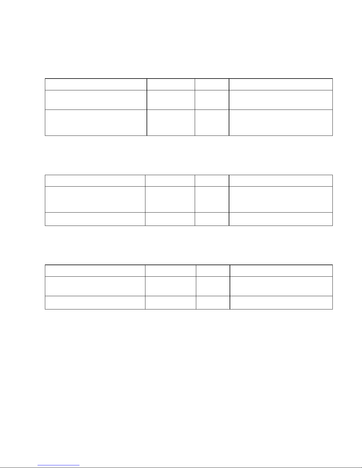
Description of the electrical connections
Terminal block identification
IN = input, OUT = output
No. Terminal Type Function Comment
- PE IN Mains – Protective earth (5 x) Only with mains 115 / 230 V !
-
-
N
LIN Mains, N = Neutral
Mains, L = Live
Mains input
230 - 240 V AC
-
-
n
lOUT Neutral, switched (8 x)
Live, switched (8 x)
Mains voltage, max. 4 A
1
2 Flush OUT External flush valve Volt-free relay output
max. load 240 V AC, 4 A
3
4
5
LV1 OUT
Limit value output 1 – Normally closed
Limit value output 1 – Normally open
Limit value output 1 – Common
Volt-free relay output
max. load 240 V AC, 4 A
6
7
8
LV2 OUT
Limit value output 2 – Normally closed
Limit value output 2 – Normally open
Limit value output 2 – Common
Volt-free relay output
max. load 240 V AC, 4 A
9
10
11
Measuring
points 1/2 OUT
Measuring point 1 – Normally closed
Measuring point 1 – Normally open
Measuring point switch-over - Common
Volt-free relay output
max. load 240 V AC, 4 A
12
13 AUX OUT Universal output Volt-free relay output
max. load 240 V AC, 4 A
14
15
16
Alarm OUT
Fault message output – Normally closed
Fault message output – Normally open
Fault message output – Common
Volt-free relay output
max. load 240 V AC, 4 A
17
18
19
Maintenance OUT
Maintenance message – Normally closed
Maintenance message – Normally open
Maintenance message – Common
Volt-free relay output
max. load 240 V AC, 4 A
20
21
Start
┴IN External analysis start
Common earth for inputs
Only for volt-free normally open
contact!
22
23
Stop
┴IN External analysis stop
Common earth for inputs
Only for volt-free normally
open/normally closed contact!
24
25 IN1
┴IN
External measuring point switch-over
Common earth for inputs
Only for volt-free normally
open/normally closed
contact!
26
27
IN2
┴IN Universal input 2 (water meter)
Common earth for inputs
Only for volt-free normally open
contact!
28
29
OUT
┴OUT 0/4 - 20 mA or serial interface Non floating output!
28 = 0/4 - 20 mA, 29 = ┴

7 / 24
Description of display and operating features
(1) ON/OFF switch
The ON/OFF switch is located on the right-
hand side panel of the unit. Use this switch to
switch the unit on or off.
(2) Unit fuse (inside the unit)
The fuse protects the outputs against
overloads and short circuits.
3 Limit value status displays
Displays the status of the limit values LV1 (1)
and LV2 (2).
4 Text display
Displays the current analysis result as well as
all important status results and programming
data via a 4-line LCD.
5 Alarm
Indicates malfunctioning.
6 Maintenance message Function keys:
Displays a maintenance request. 9 "Manual" = manual start of an analysis
10 STANDBY = manual analysis stop/standby
7 Status display 11 "Alarm" = confirms an alarm message
Six LEDs signal the current status (analysis
and unit status) of the Testomat
®
2000 SO
3
2-
. 12 i-key
Call-up all unit information (also see i menu).
8 Programming keys
(cursor block with ENTER) 13 M-key
Use these keys to enter all the values and Call-up the programming menu for user and unit-
programming data. specific settings (also see M menu).
Display functions
Limit value status displays 1 and 2
The displays signal the status of the limit values.
1: The display is red if limit value 1 has been reached or
exceeded. The display is green if the measured value
has fallen below the set limit value.
2: The display is red if limit value 2 has been reached or exceeded.
The display is green if the measured value has fallen below the set limit value.
Measured value display
The current measured value for measuring point 1 (M1:) and 2 (M2:) are displayed in lines 2 and 3, e.g. M1: 5.6 mg/l
If the measured value has exceeded the measuring range, ">" is displayed: e.g. M1: > 20 mg/l
Limit value displays
The set limit values are displayed in the bottom display line.
Alarm and maintenance message
Display of present error messages (red) and maintenance requests (yellow).
Error messages are displayed alternately with the normal display and can only be deleted via confirmation and
elimination of the fault.

8 / 24
Status displays
The displays signal active unit components.
Description of the relay outputs
Flush external flush valve:
If a long sampling line is unavoidable for installation, we recommend the installation of a flush valve upstream of the
unit.
If the unit is used for monitoring two measuring points, also install an external flush valve to prevent incorrect
measurements caused by sample mixing.
Immediately before each analysis the external flush valve is opened for the programmed period allowing the line up to
the Testomat
®
2000 SO
3
2-
to fill with measuring water. Please ensure that the programmed flush time is sufficient.
Set the flush time under menu item
"M" ➔BASIC PROGRAM ➔PROGRAM VALUES ➔FLUSH TIMES/INTERVAL ➔EXTERNAL FLUSH TIME
LV1 and LV2 limit value outputs
Two volt-free relay contacts are available to signal that a limit value has been exceeded. The limit values, the
hysteresis and the function can be freely programmed for both contacts.
Function Type of contact Action
LV1
- active when
limit value 1 or measuring point 1
have been exceeded volt-free change-over contact
programmable:
Continuous contact
Impulse (1 - 99 seconds/minutes)
Interval (1 - 99 seconds/minutes)
Two-step controller (only for one measuring
point)
Hysteresis (1, 2 or 3 limit values exceeded)
LV2
- active when
limit value 2 or measuring point 2
have been exceeded
volt-free change-over contact
programmable:
Continuous contact
Impulse (1 - 99 seconds/minutes)
Interval (1 - 99 seconds/minutes)
Hysteresis (1, 2 or 3 limit values exceeded)
Menu values:
"M" ➔BASIC PROGRAM ➔PROGRAM VALUES ➔LIMIT VALUES
"M" ➔BASIC PROGRAM ➔PROGRAM VALUES ➔FUNCTION LV1
"M" ➔BASIC PROGRAM ➔PROGRAM VALUES ➔FUNCTION LV2
"M" ➔BASIC PROGRAM ➔PROGRAM VALUES ➔HYSTERISIS LV1
"M" ➔BASIC PROGRAM ➔PROGRAM VALUES ➔HYSTERISIS LV2
Measuring points 1 or 2 Measuring points switch-over
If the unit is used for monitoring two measuring points, the solenoid valves (individual valves or one 3/2-way control
valve) of the corresponding sampling line have to be connected to this input. The switch-over can occur automatically:
The analyses are carried out alternately from measuring point 1 or 2.
Or via an external request: Input IN1 active = analysis of measuring point 2
The terminals are strictly allocated to the measuring points.
Terminal 9 = Measuring point 1
Terminal 10 = Measuring point 2
"M" ➔BASIC PROGRAM ➔PROGRAM VALUES ➔MEASURING POINTS 1/2

9 / 24
AUX programmable function output
The functioning of this volt-free relay output is programmable:
1. For contact prior to an analysis, e.g. to switch on a cooler
"M" ➔BASIC PROGRAM ➔PROGRAM VALUES ➔FUNCTION AUX ➔CONTACT PRIOR TO ANALYSIS
and/or
2. For reporting a current analysis
"M" ➔BASIC PROGRAM ➔PROGRAM VALUES ➔FUNCTION AUX ➔CONTACT FOR ANALYSIS
or
3. For contact when the input valve is open
"M" ➔BASIC PROGRAM ➔PROGRAM VALUES ➔FUNCTION AUX ➔CONTACT SUCTION
Alarm fault message output
The "Alarm" output is a volt-free change-over relay contact. During trouble-free operation the contact between the
terminals 15 – 16 is closed and the one between terminals 14– 16 is open. In case of a voltage breakdown, the
contact between the terminals 14 – 16 is closed and the one between terminals 15– 16 is open.
The unit is equipped with a range of monitoring functions. You can define the individual statuses as a fault and
program the corresponding message either as a continuous contact (A) or as a message impulse (M).
- With a continuous contact, the "Alarm" output remains activated (terminals 15 – 16 closed) as long as the fault
persists.
- With a message impulse, the output is switched 'on' for 2 seconds and then switched 'off' for 5 seconds.
- If several faults with differently programmed messages are signalled simultaneously, the output is switched to
continuous contact.
- The red LED "Alarm" and the text on the display indicate a fault.
- The fault message signal at the "Alarm" output is deleted by confirming the fault via the "Horn" key.
- The error message can only be deleted if the fault has been eliminated.
- Exception: The maintenance date has been exceeded. This message is confirmed in the M menu, see below
(maintenance).
- Each new fault is entered into the error history (also see i menu, page 16).
The following faults activate the "Alarm" output and are displayed:
The following statuses always trigger a fault message: Statuses which can be programmed as a fault:
Power failure Low reagent level
Low water level Measuring fault soiling
Function fault optics Measuring fault turbidity
Function fault dosing pump Transfer error
Function fault drain outlet Measuring range exceeded
Function fault failure 24V Maintenance interval exceeded
Descriptions of the error messages can be found under “Error messages / Troubleshooting”
Maintenance maintenance message
The "Maintenance" output is a volt-free change-over relay contact. During trouble-free operation without a
programmed maintenance interval the contact between the terminals 17 – 19 is closed and the one between terminals
18– 19 is open.
The unit is equipped with a range of monitoring functions and a programmable maintenance interval. The respective
maintenance message is always a continuous contact.
A maintenance request is displayed via the yellow "Maintenance" LED.
The maintenance display can only be deleted once the status has been corrected or after the maintenance request
has been confirmed.
"M" ➔SERVICE ➔CONFIRM MAINTENANCE
The following statuses activate the "Maintenance" output:
Low reagent level
Measuring chamber soiled (Measuring fault soiling)
Maintenance date reached
Further program and maintenance descriptions can be found under “Program menu ‘M’” and “Maintenance”
respectively.
10 / 24
Description of the signal inputs and outputs
☞
Only connect the signal inputs "Start", "Stop", "IN1" and "IN2" with volt-free contacts!
Start external analysis start
Stop external analysis stop
Function Type of contact Test time Action
Start
external analysis start
(e.g. from the process controller)
normally open
volt-free!
none In EXTERNAL operating mode an
analysis is started by triggering a contact
at the input
Stop
external analysis stop
(e.g. via flow controller or process
controller)
programmable
normally closed/
normally open
volt-free!
none As long as the contact at the input is
'open' or 'closed', no analyses are
carried out.
"M" ➔BASIC PROGRAM ➔PROGRAM VALUES ➔INPUT STOP
IN1 and IN2 universal inputs
Function Type of contact Test time Action
IN1
external measuring point switch-over
(2 measuring points externally
programmed)
programmable
normally closed/
normally open
volt-free!
none As long as the contact at the input is
'open' or 'closed', analyses are carried
out from measuring point 2.
IN2
Water meter input
normally open
volt-free!
none Quantity recording for starting an
analysis
"M" ➔BASIC PROGRAM ➔PROGRAM VALUES ➔INPUT IN1
OUT interface output (optional)
Function Connection Test time Action
Programmable interface
0 - 20 mA
4 - 20 mA
max. load 500
Ohms
- programmable
Measured value measuring point 1 or 2
Serial interface RS 232
serial bus
(2-wire cable)
- See description of the interface card
RS910
Change the function of the output by exchanging the plug-in circuit board.
"M" ➔BASIC PROGRAM ➔PROGRAM VALUES ➔INTERFACES

11 / 24
DISPLAY in mg/l *
Display in ppm
DISPLAYED UNIT
▲
▲▲
▲▼
▼▼
▼
ME
MEASURING POINTS
▲
▲▲
▲▼
▼▼
▼
M E
1 MEASURING POINT *
2 Measuring points ext.
2 Measuring points
TIME-CONTROLLED *
Volume interval
MODE OF OPERATION
▲
▲▲
▲▼
▼▼
▼
ME
External (Start)
Function characteristics
Operating modes (analysis controller)
1. Time control: Internal triggering via a timer. Shortest interval = 0 minutes
between analyses, longest interval = 99 minutes.
(Also see “Function characteristics / Time setting”)
☞
The analysis interval is determined by the duration of the supplementary program AUX, the set flush times
(internal and external), the programmed interval and the duration of the analysis. The analysis duration
depends directly on the measured value.
2. Quantity control: Triggered by the water meter.
Minimum interval = 1 litre, maximum interval = 9999 litres.
The analysis is carried out once the programmed water quantity has been measured. The line and the measuring
chamber are flushed prior to the analysis (observe the programmed flush times).
3. External analysis start by triggering a contact at the start input
☞
The current analysis interval can be interrupted by triggering a contact at the stop
input.
Analysis cycle (example with schematic cycle diagram)
1 Supplementary program AUX prior to analysis
2 Flush the line and measuring chamber (observe the flush time of the sampling
line), T
SE
und T
SI
3 Fill measuring chamber
4, 5 Check the sample for soiling (stirring mechanism is switched on)
Dose the reagents: 8 x reagent A and 8 x reagent B
Subsequent 3-minute reaction time
6 Evaluate and display reaction
7 Drain the measuring chamber
8 Waiting period until the next analysis (time or quantity analysis interval),
Tp T
I
= total analysis interval
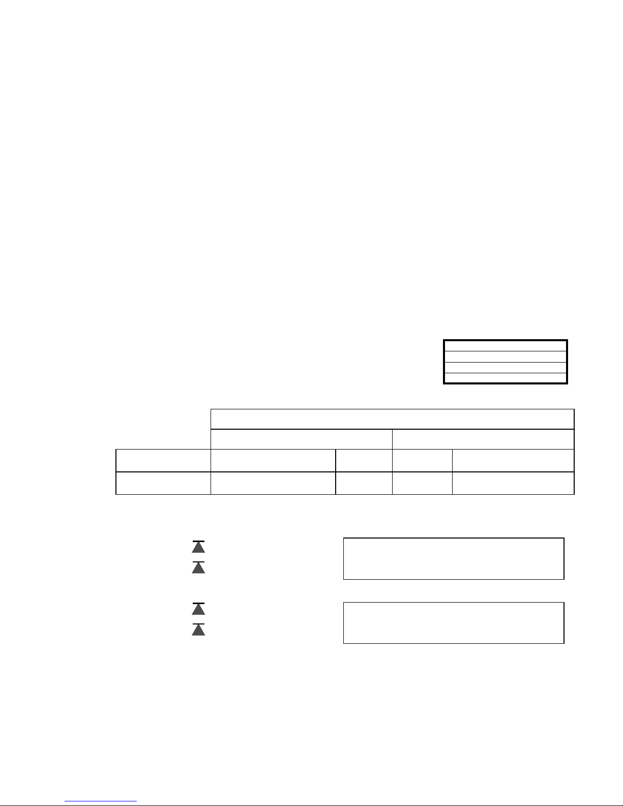
Display unit
It is possible to program the unit of the displayed value. mg/l as well as ppm can be
selected. All the following inputs and displays will be displayed in the programmed
unit.
The device has a measuring range 0-20mg/l with two resolution ranges 0-9.9mg/l
and 10-20mg/l.
Measuring points
The Testomat 2000 SO
3
can be used for monitoring 2 measuring points. Measuring
point switch-over can occur either automatically or by triggering a contact (or
normally closed) at input IN2. If the external measuring point switch-over has been
programmed ("2 MEASURING POINTS EXTERNAL"), a respective controller (e.g.
timer) has to be connected to IN1 (volt-free contact required!). The active status of
IN1 has to be programmed accordingly.
12 / 24
LIMIT VALUES
▲
▲▲
▲▼
▼▼
▼
M E
Limit val. 2: 0.50 mg/l
LIMIT VAL. 1: 1.20 mg/l
Time setting
Internal flushing
To ensure that the analysed sample represents the current value, the sampling line must be sufficiently flushed. If the
plant has been out of operation for a longer period or in the case of long analysis intervals, we recommend you to
select a flushing time greater than 60 seconds. Flushing starts by simultaneously opening the inlet and the outlet valve
of the Testomat
®
2000 SO
3
2-
.
Example: For connections longer than 3 m and with an internal hose diameter of 6 mm a minimum internal
flushing time of 10 seconds is required to ensure that a valid sample is taken from the sampling line. The required
quantity of flush water for 1-minute internal flushing is 0.5 litres.
☞
The analysis interval depends directly on the programmed flushing time. If, e.g., a flushing time of 60 seconds
has been set, the actual analysis interval cannot be less than 60 seconds.
External flushing
If very short analysis intervals are required, or if a very long (several metres) sampling line or a line with a large
diameter are used, an external flush valve should be installed upstream of the Testomat
®
2000 SO
3
2-
. The external
flush valve has to be connected to the "Flush” outlet. The external flushing time for the valve depends, just as the
flushing time for unit flushing does, on the length and diameter of the supply line to the Testomat
®
2000 SO
3
2-
.
Interval pause
If the analysis is triggered via a timer, the interval between two analyses (plus flushing time) is determined by the
interval pause. The shortest interval can be 0 minutes. In this case, analyses are carried out continuously. The longest
interval is 99 minutes.
Limit value monitoring
It is possible to program the limit values on a continuous scale. The limit value range
depends on the used reagent type and the programmed unit.
Example:
Number of measuring points
1 2
Function LV1 1, 2 or 3 exceeds upper
limit value
upper LV Measuring
point 1
1., 2. or 3 exceeds upper
limit value
Function LV2 1., 2. or 3 exceeds upper
limit value
lower LV Measuring
point 2
1., 2. or 3 exceeds upper
limit value
Two limit value outputs are available for monitoring. The functions of these outputs can be programmed independently
of each other.
Two limit values: 1 LV1 = Limit value 1
2 LV2 = Limit value 2
Two measuring points: 1 LV1 = Measuring point 1
2 LV2 = Measuring point 2
If the limit value LV1 has been exceeded, the limit value control display LV1 lights up RED and the relay output LV1
reacts as programmed in the switch function. If this limit value has not been exceeded, the display lights up GREEN.
The same applies for the limit value LV2.
If the unit is used for monitoring two limit values,
the limit value outputs are permanently allocated
to these limit values!
If the unit is used for monitoring two measuring
points, the limit value outputs are permanenty
allocated to these measuring points!

13 / 24
WATER METER
▲
▲▲
▲▼
▼▼
▼
M E
1 LITRE/IMPULSE
2,5 Litres/Impulse
5 Litres/Impulse
10 Litres/Impulse
100 Litres/Impulse
*
500 Litres/Impulse
1000 Litres/Impulse
HYSTERESIS LV1
▲
▲▲
▲▼
▼▼
▼
M E
Analysis (1,2,3) 1
Hysteresis
The respective limit value output only switches after the 1st, 2nd or 3rd limit value
has been exceeded (suppression of the first or the second measured value).
This increases the reliability of the analysis evaluation, e.g. after the measuring
point has been switched over or if the sampling line has not been flushed sufficiently. The hystereses of the two
outputs LV1 and LV2 can be set independently of each other.
Function: A further analysis is carried out immediately after the limit value has been exceeded for a hysteresis of 2.
The respective output only reacts if the limit value of this analysis is exceeded again. If a hysteresis of 3 has been set,
the respective output only reacts after the limit value has been exceeded for the 3rd time in succession.
(The basic setting for LV1 and LV2 is 1)
Logic functions of the limit value outputs LV1 and LV2
Schematic representation of the logic functions
Switch function 0, duration
If the limit value LV1 or LV2 has been
exceeded, the output relay LV1 or LV2 reacts.
If the measured value falls below the limit value
LV1 or LV2 without lock out, the relevant relay
drops out again.
Switch function 1, impulse
If the measured value exceeds the limit value
LV1 or LV2, the relevant output reacts for a
settable time t.
The respective output always remains switched
for the set time, irrespective of how long the
limit value has been exceeded.
Switch function 2, interval
If the limit value has been exceeded, the
respective output switches at intervals with the
settable impulse/pause time t.
Switch function 3, two-point
If the upper limit value LV1 has been exceeded, the output relay LV1 switches. If the lower limit value LV2 falls below
the set limit, the output relay LV1 drops out again.
The output relay LV2 switches according to the programmed switch function.
☞
This function is only possible if different values are used for the limit values LV1 and LV2 with just one
measuring point. For example, LV1 = 0.2 mg/l and LV2 = 0.3 mg/l.
Function IN1
External measuring point switch-over when monitoring 2 measuring points without automatic measuring point switch-
over. If the external measuring point switch-over has been programmed, a respective controller (e.g. timer) has to be
connected to IN1 (volt-free contact required!). The active status of IN1 has to be programmed accordingly.
Water meter
It is necessary to connect a water meter to input IN2 for quantity-dependent
analysis triggering. Program the corresponding water meter rating under the menu
item "WATER METER”.

14 / 24
ALARM/MESSAGE
▲
▲▲
▲▼
▼▼
▼
M E
REAGENT LOW LEVEL A
Ff. optics A
Low water pressure A
Mf. turbid M
Ff. dosing pump A
Ff. outlet to drain A
Mf. dirtiness M
power failure 24 V A
Meas. range exceeded M
A = Alarm / M = Message / - = no action
Ff. = Function fault
Mf. = Measuring fault
A/M
A/M/-
A/M
A/M
A/M
A/M/-
A/M/-
A/M
A/M/-
Transfer error M
A/M/-
Maint. int. exceeded M
A/M/-
FUNCTION AUX
▲
▲▲
▲▼
▼▼
▼
M E
Contact during analysis
CONTACT BEFORE ANALYSIS *
Contact "suction"
Time: 00m:10s
SERVICE II
▲
▲▲
▲▼
▼▼
▼
M
E
CALIBRATION
Reset operating time
Maintenance interval
CALIBRATION
▲
▲▲
▲▼
▼▼
▼
M E
CALIBRATION VALUE 0.35mg/l
Calibration start
Cal. factor 1.0
OPERATING TIME
▲▼
▲▼▲▼
▲▼
M E
000023h
Reset
MAINTENANCE INTERV.
▲▼
▲▼▲▼
▲▼
M E
001d
Alarm / Message
The unit is equipped with an alarm relay output for signalling faults. The events
which mean a fault at the unit or are intended to trigger a message, can either
trigger an alarm (continuous contact) or a message (2-second impulse).
Certain unit faults always trigger an alarm or a message!
The faults are recorded and stored in the error history if the event has been
programmed as an alarm or message. For example, if a low reagent level has not
been programmed as an ALARM or a MESSAGE, it is not registered in the error
history. Up to 20 error messages can be stored. A list of these errors can be
opened in the information menu. The information stored per event is the time
(day, month, year and hour) and the type of the error.
☞
The error messages are lost after a power failure.
Function AUX
The AUX relay output can be programmed for the following control functions:
- As a function output for the contact with programmable duration prior to
or during the analysis or during the open period of the inlet valve.
(Also see Function characteristics, Operating modes, Analysis cycle)
This contact can be used, e.g., to control a feed pump for sampling. It is also
possible to control the cooling water inlet of an upstream cooler via a solenoid valve. This way the cooling water only
flows when required, i.e. when an analysis is being carried out.
Service II
The service II menu contains various functions for monitoring the operation of the
unit.
☞
The functions in the service II menu directly influence the operation and
monitoring functions of the unit!
Calibration
Calibration can, e.g., be carried out to compensate for negative influences caused
by foreign ions. A standard solution or the value of the sample water determined
via a laboratory analysis is required for this.
Calibration value: Enter the known value of the standard solution or the determined value of the sample water.
Start calibration: Select menu item “Calibrate Start” and press the “ENTER” key: A reference measurement ist
carried out and the correction factor is determined. The calibration procedure with a standard solution can be found
under “Maintenance / Monitoring/Calibration with standard”
.
Correction factor: It is also possible to enter a calculatively determined factor for the correction of the display. The
current factor is displayed after calibration.
Reset operating time
After replacing the dosing pump or the measuring chamber holder, it is possible
to reset the current operating time to 0 hours.
"M" ➔BASIC PROGRAM ➔SERVICE II ➔RESET OPERATING TIME
The current operating time can be requested in the information menu:
i" ➔INFORMATION ➔OPERATING VALUES
Maintenance interval
Observance of the maintenance intervals is monitored and displayed by the
Testomat
®
2000 SO
3
2-
. Program the desired maintenance interval in days here.
( 0 days equals no maintenance interval. )

15 / 24
INTERFACES
▲▼
▲▼▲▼
▲▼
M E
Type 0-20 mA
Type RS232
Type 4-20 mA *
Interfaces (optional)
Current interface 0/4-20 mA
Another possibility for monitoring the analysis is the connection of a recorder. The
unit is equipped with a programmable current output for this purpose.
Standard values of 0 - 20 mA or 4 - 20 mA can be selected.
☞
The maximum load of 500 Ohms should not be exceeded!
For faults and when using very long cables (approx. 20 m) a screened cable should be used if possible.
Serial interface RS232
The Testomat
®
2000 SO
3
2-
can also be connected to a log printer via the serial interface RS232 to enable the printout
of measuring results and error messages. Analyses can then be continuously logged. This option is only possible in
connection with the plug-in card RS910 (Art. no. 270310).
Menu structure
Display function
"i" (key) "M"
Information menu Program menu
Selection and input
Menu start
Use either the "M" or "i" key to open one of the menus.
Selection
The current line position is displayed in CAPITAL LETTERS. Use the "ENTER" key to activate a line, i.e. a submenu is
opened. Use arrow key "" to display the next parameter below the lowest display line.
You can "scroll" the menu.
Input (only possible in the "M" menu)
Select a programming step via the arrow keys "" and "" and activate the input function by pressing the "ENTER" key.
The first digit to be changed flashes when entering digits.
Use the arrow keys "" and "" to change the value.
Use the arrow keys "" and "" to confirm the input and simultaneously change to the next or previous digit (now
flashing).
Exit the input function via the "ENTER" key.
The following line is activated.
Use the "M" key to go to the superordinate menu.
Menu end
Use the "M" or "i" key to return to the superordinate menu. After returning from the highest menu level, the unit is in
display mode again.

16 / 24
i button
CUSTOMER SERVICE i
E.g. your name and adress
i
i
E
E
E
i
i
ERROR REGISTRATION
▲▼
i E
Error display, if it is programmed as
alarm
MODE OF OPERATION
Displayed unit
PROGRAM VALUES
▲▼
i E
Measuring points 1 or 2
Flush times/interval
Parameter
Limit values
Reagent level A 060%
Operating time 00629h
OPERATING VALUES
▲▼
i
Software version 73EXXX
Maintenance
Program values
Error registration
CUSTOMER SERVICE
Operating values
INFORMATION
▲▼
i E
Maintenance interval 000d
MAINTENANCE i
Maintenance in 000d
Up to 20
error messages
Ff. optics
Ff. outlet to drain
Ff. dosing pump
Ff. dosing fault
Mf. dirtiness
Transfer error
power failure 24 V
Plant control
REAGENT LOW LEVEL
Power failure
Low water pressure
S u l f i t
0 - 20
M1: 0.6 mg/ltr
^1: 1.0 mg/ltr ^2: 5.0 mg/ltr
Ei
1
2
3
4
5
6
i
E
From
POWER FAILURE i
To
E
4 lines are displayed
(black scale)
Res. operat. time 00126h
Residual analyses 1386
Reagent level B 060%
Information menu "i"
Structure of the "i" menu
In the information menu it is possible to
request active settings and statuses of
the unit, the error history, the date for the
next maintenance and the customer
service address.
Call (1)
Use the "i" key to open the information
menu "i".
Customer service (2)
Display of the customer service address
or, e.g., a service telephone number.
These three lines can be freely
programmed in the basic program
(password protected):
"M" ➔BASIC PROGRAM ➔
CUSTOMER SERVICE
Operating values (3)
Display of the current values.
Program values (4)
Use the arrow keys to open the menu item "Program values”. Open the list of the set values by pressing "ENTER".
The current setting of a parameter can be requested by pressing "ENTER":
For example (4a): "i" ➔INFORMATION ➔PROGRAM VALUES ➔PARAMETER
An asterisk indicates the selected function. (In this context there are no active lines)
Error history (5)
Open the error history by pressing the "i" and "ENTER” key. The error history is a list of the errors or statuses which
have occurred during current operation. This list is lost after a power failure and the recording is restarted.
If no errors have occurred since start-up, the last switch-on time of the unit is displayed, e.g.:
POWER FAILURE
from 16.06.03 06:56
to 16.06.03 07:09
Maintenance (6)
Display of the next maintenance date and programmed maintenance interval.
It is possible to set the maintenance interval in the basic program (password protected):
"M" ➔BASIC PROGRAM ➔SERVICE II
Refer to the chapter entitled Maintenance for further maintenance information.

17 / 24
Program menu "M"
Call: (1)
Use the "M" key to open the program menu
"M".
It is possible to call up all the functions
without password protection except for the
basic program.
Service I (2)
Input reagents (3)
Enter the new filling levels after each refill
or reagent bottle change. Once you have
selected the menu item for entering the
filling level "Reagent X Filling (0 - 100%)"
via the "ENTER" key, the value is preset to
100%. If a full bottle has been connected,
confirm this value via the "ENTER" key.
If the filling of the bottle differs, enter the
corresponding value.
Manual operation (4)
After confirming the information message
(4) via the "ENTER" key, it is possible to
select and activate the desired function by
using the arrow keys and pressing the
"ENTER" key.
These functions are used for monitoring the
functions and for commissioning.
☞
All manual functions can only be
selected during an analysis pause.
Analyses are not carried out during
manual operation. All signal inputs and outputs are locked.
Flush (5)
Press the "ENTER" key to start the flushing of the sampling line via the internal valves. Press the "ENTER" key
again to cancel this function.
Flush chamber (6)
Press the "ENTER" key to flush the measuring chamber once.
Drain chamber (7)
Press the "ENTER" key to open the outlet valve in order to drain the water from the measuring chamber.
Press the "ENTER" key again to cancel this function.
Fill chamber (8)
Press the "ENTER" key to fill the measuring chamber.
Confirm maintenance (10)
After maintenance has been carried out, confirm it by pressing the "ENTER" key and exit this item via the "M" key.
The maintenance interval is restarted.
☞
Confirm a maintenance request once the maintenance interval has expired in the M menu. The displayed
message is deleted and the “maintenance” output reset.
Refer to the chapter entitled Maintenance for further details on maintenance intervals.
Diagnosis (11)
It is possible to request the current statuses of the signal inputs and outputs in a list.
Active statuses are marked with an *. (See menu structure)
Prozeß
M - key
SERVICE I
▲
▲▲
▲▼
▼▼
▼
M E
INPUT REAGENT
Manual operation
Confirm maintenance
DATE / TIME OF DAY
▲
▲▲
▲▼
▼▼
▼
M E
DATE 11.01.00
Time of day 23.59
PROGRAM MENU
Testomat 2000 SO
3
BASIC PROGRAM
INPUT REAGENT
▲
▲▲
▲▼
▼▼
▼
M E
Reagent A LEVEL: 100%
Reagent B level: 100%
E
Day of week Monday
MANUAL OPERATION
▲
▲▲
▲▼
▼▼
▼
M E
FLUSH *
Drain chamber
Fill chamber
Flush chamber
NOTE ! M E
Manual function without
monitoring!
go on with enter key
DIAGNOSIS
▲
▲▲
▲▼
▼▼
▼
M E
OUTPUT LV1
Output LV2
Output M 1/2
Output Flush
Output AUX
Output Alarm *
Output Maintenance *
Output OUT 255
Input Start
Input Stop
Diagnosis
E
1
2
3
4
4
5
6
7
8
10
11
12
E
MAINTENANCE M E
Confirm the course with enter!
E
PROGRAM
▲
▲▲
▲▼
▼▼
▼
M E
SERVICE I
Basic program
Date/Time of day
E
E
Input IN1 *
Input IN2 *
E
E
Description on the next
page
S u l f i t 0 - 20
M1: 2.6 mg/l
^1: 3.0 mg/l ^2: 5.0 mg/l

18 / 24
Date/Time (12)
Set the time and date by selecting and activating the desired function via the arrow keys and the "ENTER” key.
Subsequently press the "M" key again to save the setting and to return to the display function.
Basic program
This menu item can only be accessed after entering the password!
Example for password entry:
>BASIC PROGRAM 07:25
21.04.00 07:25
Password: ____ _ _ _ _
(5270)
After entering the password and confirming it via the "ENTER" key, it is possible to carry out basic programming of the
unit and to select various service functions (e.g. calibration).
Program values
Press the "M" and "i" key to call the basic factory default setting and to switch on the unit. The values and settings of
the basic default setting are described in the structure of the basic program on page 19.
The following program values can be entered and stored in the basic program via the respective menu items:
Abbreviations: s = seconds
m = minutes
h = hours
d = days
l = litres
Table of contents
Other Testomat Measuring Instrument manuals


