Tesup i-500 User manual

USER
MANUAL
-Keep
handy
at
the
place
of
use
-
TESTED & CONTROLLED
✅
TEST NUMBER
Date
" # $ % & ' ( )
TESUP
GLOBAL
UK
|
DE
|
FR
|
ES
|
IT
|
TR
|
CA
|
US
WARRANTY FOR
2
Year(s)
WARRANTY NUMBER
Date
"#$%&'()
Wind
Turbine
i-500
INVOICE NUMBER

1Contents
1 Contents ................................................................................................. 2
2 General.................................................................................................... 4
2.1 About this translation of the original instructions ....................................... 4
2.1.1 Revision status of the original instructions .................................................. 4
2.1.2 Conditions for installing and operating the wind turbine system ................ 4
2.1.3 Availability of the instructions....................................................................... 4
2.2 Conventions used in this translation of the original instructions.................. 4
2.2.1 Other symbols used ...................................................................................... 5
2.2.2 Information ................................................................................................... 5
2.3 N
a
me
of
t
he
ma
nu
f
a
c
t
ure
r
...........................................................................
5
2.4 Warranty and liability ................................................................................. 6
2.5 Product feedback ........................................................................................ 6
3 Technical description.............................................................................. 6
3.1 Intended use .............................................................................................. 6
3.2 Reasonably foreseeable misuse.................................................................. 6
3 Main components........................................................................................ 7
3.4 Main components of the wind turbine ....................................................... 8
4 Technical data........................................................................................ 9
5
Operating and storage conditions.........................................................
5.1
P
e
r
mi
s
s
i
bl
e
ope
r
a
t
i
ng
a
nd
s
t
or
a
ge
c
ond
i
t
i
ons
.
..
..
..
..
..
..
..
..
..
..
.
..
..
..
..
.
..
..
..
..
..
.
5.1.1 Storage ......................................................................................................
5.1.2 Operation ....................................................................................................
6 Safety information .................................................................................
6.1 Modifications or changes by the user .........................................................
6.2 Residual risks..............................................................................................
6.3 Personnel requirements..............................................................................
7 Preparing to use the system....................................................................
7.1 Shipping ......................................................................................................
7.1.1 As-delivered condition ................................................................................
7.1.2 Scope of supply ..........................................................................................
10
10
10
10
10
10
10
10
11
11
11
11
TESUP UK | DE | FR | ES | IT | TR | CA | US
TESUP
1

7.2 Requirements at the place of use ...............................................................
7.2.1 Permissible wind class, footprint and minimum clearances .......................
7.2.2 Tower foundation ........................................................................................
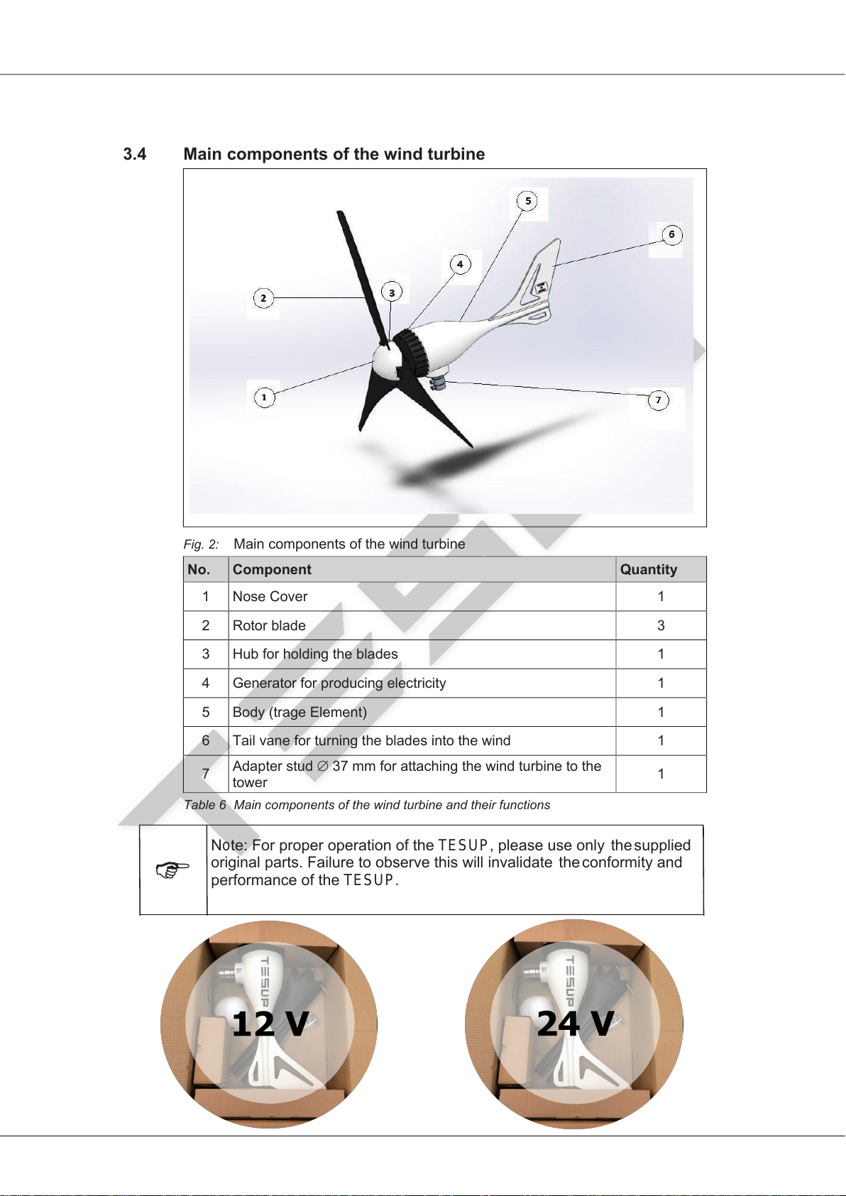
7.3 Unpacking the components ........................................................................
7.4 Assembling the wind turbine..................................................................
7.5 Electrical connections .................................................................................
7.6 Erecting the wind turbine ............................................................................
8 Normal operation ..................................................................................
8.1 Switching on the wind turbine system.........................................................
8.2 Restart after an emergency ........................................................................
9 Shutting down the wind turbine system ...............................................
9.1 Emergency shut-down ...............................................................................
9.2 Temporary shut-down................................................................................
9.3 Prolonged shut-down.................................................................................
10 Maintenance .........................................................................................
10.1 Safety precautions during maintenance work.............................................
10.2 Inspection and maintenance schedule .......................................................
10.3 Maintenance and cleaning by the user .......................................................
11 Troubleshooting and diagnostics ...........................................................
11.1 Errors with LED...........................................................................................
11.2 Errors without LED......................................................................................
12 Removal from service and disposal .......................................................
12.1 Final decommissioning of the wind turbine system ....................................
12.2 Disposal of the wind turbine system and components ...............................
13 Declaration of conformity .....................................................................
14 Index......................................................................................................
15 Notes ....................................................................................................
16
P
e
r
f
o
r
m
a
n
ce
Ch
a
r
ts……
……
……
……
……
……
……
……
……
……
……
……
…
……
……
…
24
11
11
12
13
13
14
15
16
16
16
16
16
16
16
17
17
17
17
18
18
18
20
20
20
21
22
23
TESUP UK | DE | FR | ES | IT | TR | CA | US
TESUP
2

2General
2.1 About this translation of the original instructions
2.1.1 Revision status of the original instructions
Revision date: ..........................................................................................20.02.2017
Revision index: ....................................................................................................... 00
2.1.2 Conditions for installing and operating the wind turbine system
Please make sure that
•The wind turbine system has been erected correctly by a suitably trained
person.
•All operating personnel have read and fully understood this translation of the
original instructions
•The wind turbine system is properly maintained and repaired.
2.1.3 Availability of the instructions
Keep this translation of the original instructions handy at all times, so that it can be
referred to by all persons working on or with the wind turbine system.
2.2 Conventions used in this translation of the original instructions
Safety information is always identified by a signal word and in some cases also by
a hazard-specific symbol.
DANGER!
Immediate danger!
Non-observance of the safety instructions will result in serious or fatal injury!
WARNING!
Potentially dangerous situation!
Non-observance of the safety instructions can result in serious or fatal injury!
CAUTION!
Potentially dangerous situation!
Non-observance of the safety instructions can result in minor or moderate injuries!
IMPORTANT!
Potentially dangerous situation!
Non-observance of the safety instructions can result in damage to property or
pollution of the environment!
TESUP UK | DE | FR | ES | IT | TR | CA | US
TESUP
3

2.2.1 Other symbols used
The following symbols are used in this translation of the original instructions as well
as on the wind turbine system itself:
Warning signs
General warning!
Danger: High voltage!
May start without warning!
Environmental hazard!
Table 1 Warning signs
Mandatory signs
Read manual before operating!
Isolate before opening!
Table 2 Mandatory signs
2.2.2 Information
Note
Indicates general information and recommendations.
2.3 Name
of
the
manuf
acturer
TESUP UK | DE | FR | ES | IT | TR | CA | US
TESUP
4

2.4 Warranty and liability
The “General Terms of Sale and Delivery” of the manufacturer or his authorised
representative apply.
2.5 Product feedback
Please notify the manufacturer or his authorised representative about any of the
following
•Accidents
•Potential safety hazards associated with the wind turbine system
•Ambiguities in this translation of the original instructions
•Description of the wind turbine system
3Technical description
3.1 Intended use
•The wind turbine system may only be used as a “small wind turbine system”
(SWTS) to generate power in accordance with EN 61400-2.
•The wind turbine system may only be operated in accordance with the ratings
and in the approved wind class (refer to the technical data).
•Observance of the original instructions and compliance with the maintenance
and repair instructions are essential preconditions of use for the intended
purpose.
3.2 Reasonably foreseeable misuse
All forms of use which deviate from or exceed the limits of use described above are
considered to be contrary to the intended purpose. The manufacturer is not liable
for any damage resulting from such use.
No liability will be accepted by the manufacturer if the equipment has been altered
as well as in the event of improper assembly, installation, start-up, operation,
maintenance or repair.
Only original parts supplied by the manufacturer are approved as spare parts or
accessories. Any spare parts or accessories not supplied by the manufacturer
have not been tested for operation and could be detrimental to reliability. No
liability will be accepted by the manufacturer for any damages which result from the
use of non-approved spare parts or accessories.
Reasonably foreseeable misuse includes:
•Operation outside the manufacturer’s specification
•All modifications or changes to the wind turbine system without the
manufacturer’s written approval!
•Use
of
parts
other
than TESUP
original
parts
.
•Operation in non-approved SWTS classes.
•Operation in strong winds or hurricanes.
TESUP UK | DE | FR | ES | IT | TR | CA | US
TESUP
5

3.3 Main components
Fig. 1: Main components of the wind turbine system
No. Component Function
Emergency shut-down.
When pressed, the wind turbine must be short-
circuited.
5Solar panels
(optional) Convert solar energy into electrical energy
6To converter
Table 5 Main components and their functions
Wind turbine
1 Converts wind energy into electrical energy
2
Switch switch AC
Emergency Stop Button
(optional)
e
Generates electrical voltage (12 / 24 / 48 VDC).
The iSTA Breeze charge controller has 40 A fuse
protection
Charge controller
3
4Battery Stores electrical energy
Converts 12 / 24 VDC into 110 / 220 VAC
(optional)
Recommendation:
TESUP UK | DE | FR | ES | IT | TR | CA | US
The TESUP charge controller has 40 A fuse protection.
TESUP
6

3.4 Main components of the wind turbine
Fig. 2: Main components of the wind turbine
No. Component Quantity
7Adapter stud ∅37 mm for attaching the wind turbine to the
tower 1
Table 6 Main components of the wind turbine and their functions
1 1
2 Rotor blade 3
3 Hub for holding the blades 1
4 Generator for producing electricity 1
5 1
6 Tail vane for turning the blades into the wind 1
o
TESUP
TESUP
TESUP UK | DE | FR | ES | IT | TR | CA | US
TESUP
TESUP
7

4Technical data
Generator
Type Permanent magnet rotor, brushless, direct drive, maintenance-
24V
48V
Current 3-phase
Start of charging Approx. 3 m/s (wind speed)
Test standard
EN 61000-6-1 (electromagnetic compatibility – immunity)
EN 61000-6-3 (electromagnetic compatibility – emissions)
Rotor blades
Direction of rotation Clockwise, looking from front end
Noise emissions
[dB(A)]
Table 7 Technical data
Designation
i-0-500
12V
24V
A
A
12V
24V24V
48V
A
A35A
1A
5A
A
free
Weight [kg] .
Max. power
0–330
Open circuit voltage [VAC] 0–330
[V]
[V]
Direction of rotation
Housing material Plastic
Plastic
Hub flange
Diameter, approx. [m] 1. 1. .25 .
Weight per rotor
blade, [g] 200
Carbon granules
Max. speed [rpm]
TESUP UK | DE | FR | ES | IT | TR | CA | US
TESUP
8

•Ambient temperature: -25 to +40°C
•Place of use: Max. SWTS Class III acc. to EN 61400-2
The wind turbine system is in conformity with the European Machinery Directive
2006/42/EC provided
only
original
TESUP
components
are
used
and
subject
to
proper
erection. The
us
e
of components
from
other
manufacturers
as
well
as
modifications
or
changes
to
t
he
wind
t
urbine system
by
t
he
user
are
prohibited
and
could
render
the
declaration
of conformi
ty
invalid!
Any residual risks which arise as a result of operation or maintenance are
described in the relevant sections of these instructions.
All work on the wind turbine system must be carried out by authorised persons!
Such persons must be familiar with the safety devices and regulations prior to
carrying out the work.
Authorised persons are defined as follows:
Operating mode Necessary qualifications
Erection Suitably trained persons
Normal operation Trained personnel
Cleaning Trained personnel
Maintenance Suitably trained persons
Repair Manufacturer
Table 8 Personnel requirements
•Ambient temperature: to +40°C
•Storage location: Dry, frost-free
.1 Permissible operating and storage conditions
.1.1 Storage
.1.2 Operation
Safety information
.1 Modifications or changes by the user
.2 Residual risks
.3 Personnel requirements
TESUP UK | DE | FR | ES | IT | TR | CA | US
O
perating
and
storage
conditi
ons
TESUP
9

WARNING!
Danger to life due to operation in non-approved wind classes!
The wind turbine system may only be operated at Class III wind sites.
For information on local wind classes, please contact the responsible authorities or
your nearest meteorological office.
Fig. 3: Footprint and minimum clearances
The place of use must be free of obstacles; alternatively, the wind turbine must be
erected with a sufficient height (refer to Fig. 3:). Obstacles are defined as houses,
hedges, trees, hills, etc.
When choosing the place of use, make sure adequate room is
available to tilt the tower and blades if necessary.
H
20 H
2 H
2 H
Preparing to use the system
.1 Shipping
.1.1 As-delivered condition
The wind turbine system is shipped disassembled.
.1.2 Scope of supply
Refer to the contract documentation for the scope of supply.
.2 Requirements at the place of use
.2.1 Permissible wind class, footprint and minimum clearances
TESUP UK | DE | FR | ES | IT | TR | CA | US
TESUP
10

Fig. 4: Design of the foundation for erecting the tower
The soil must have a sufficient load-bearing capacity. The size and structure of the
foundation depend on the soil characteristics.
Recommendation:
Ask a qualified structural engineer for advice regarding the optimal
design of the foundation.
Fig. 5: Suitable guying system
.2.2 Tower foundation
TESUP UK | DE | FR | ES | IT | TR | CA | US
TESUP
11

Carefully open the packaging.
Check the shipment for completeness (refer to the shipping documents).
Separate the packaging material and dispose of it in an environmentally
responsible way.
Danger due to rotor imbalance!
Always replace the complete set of rotor blades.
Risk of injury in case of assembly at windy sites!
Choose an assembly site which is sheltered from the wind.
The assembly process requires calm weather conditions.
Fig. 6: Assembling the wind turbine
.3 Unpacking the components
.4 Assembling the wind turbine
WARNING!
TESUP UK | DE | FR | ES | IT | TR | CA | US
TESUP
TESUP
12

Fig. 7: Balancing the rotor (Y position)
Danger: High voltage!
All work on electrical equipment must be carried out by a qualified
electrician with the power switched off!
Note: To ensure proper operation, you must use an original iSTA
Breeze charge controller.
Connect a three-wire cable with a suitable cross-section (refer to Table 9 /
Table 10) and the required length to the generator.
Make the electrical connections as shown in Fig. 1:.
Connect the charge controller and the transformer as shown in the
connection diagram (refer to the relevant documentation).
Distance between
generator and charge
controller [m]
< 11 11 – 18 18 – 29 20 – 44 44 – 68 68 – 110
Cable cross-section [mm²] 2.5 4 6 10 16 25
Distance between
generator and charge
controller [m]
< 11 11 – 18 18 – 29 20 – 44 44 – 70 68 – 113
Cable cross-section [mm²] 2.5 4 6 10 16 25
Table 9 Cable cross-sectionwith V generator voltage
Table 10Cable cross-sectionwith V generator voltage
1of 2Translation of the original instructions iSTA wind turbine system 20.02.2017 I00
.5 Electrical connections
DANGER!
TESUP UK | DE | FR | ES | IT | TR | CA | US
TESUP
charge controller.
TESUP
13

Preparing to use the system
Feed the three-wire cable through the tower right up to the top.
Provide suitable strain relief.
Connect the wires to the generator.
Attach the wind turbine to the tower. Be careful not to damage the cable.
Bolt the wind turbine to the tower.
Stand the tower upright.
Align the tower vertically in all directions.
Secure the vertical tower with guy wires (refer to Fig. 5:)
Remove the short-circuit.
Fig. 8: Connecting the three-wire cable to the generato
Danger due to unsuitable tower constructions!
.6 Erecting the wind turbine
WARNING!
TESUP UK | DE | FR | ES | IT | TR | CA | US
TESUP
TESUP
TESUP masts.
TESUP
14

For information on operating the iSTA Breeze charge controller, refer to
the separate instructions.
Unlock the
emergenc
y stop bu
tt
on
or
release
t
he
brake
bu
tt
on
on t
he
TESUP
charge
controller
.
The brake is released.
The fast-
blinking
red
LED
on t
he
TESUP
charge
controller goes
out
.
The
wind t
urbine
system
supplies
power
.
Make sure the risk has been removed.
Switch on the wind turbine system (section 7.1)
Press the emergency stop button between the wind turbine and the charge
controller.
The
wind
t
urbine
is
s
hort
-
circuited via
t
he
TESUP
charge
controller
.
The
wind
turbine
is
braked.
Press
the
“
Charge
controller
OFF”
bu
tt
on
on
TESUP Charge Controller
.
Operation
is
interrupted
.
Press the
“
Charge
controller
brake
OFF
”
bu
tt
on
on t
he
TESUP
charge
controller
.
The
wind
t
urbine
is
s
hort
-
circuited
v
ia
t
he
TESUP
charge
controller
.
The
wind
t
urbine
is
braked.
Carefull
y t
il
t
the
wind
t
urbine.
Clean the
wind t
urbine
(
section
9.
3
)
Normal operation
.1 Switching on the wind turbine system
.2 Restart after an emergency
Shutting down the wind turbine system
.1 Emergency shut-down
.2 Temporary shut-down
.3 Prolonged shut-down
TESUP UK | DE | FR | ES | IT | TR | CA | US
TESUP charge controller, refers to
TESUP
15

Risk of injury when carrying out maintenance work!
Shut down the wind turbine system prior to all maintenance work.
Take steps to prevent the wind turbine system from being switched on again
by unauthorised persons.
Shut down the wind turbine system (section 8.2).
Carefully tilt the tower.
Interval Part / component Activity
Daily
Wind turbine Check for abnormal noises
Rotor blades Check that the blades turn freely
Tower Inspect for damage
Yearly2/ at
end of winter
or after
extreme
weather
events
Rotor blades
Inspect for cracks / damage and
if necessary replace
Treat with underbody protection
wax
Are the rotor blades balanced?
Tower
Check for vibration
Check the guy wires
Is the tower still aligned
vertically?
Inspect for damage
Wind turbine Check the bolts
Electrical wiring Inspect the cables for damage
Table 11Inspection and maintenance schedule
WARNING!
Danger due to damaged parts!
Shut down the wind turbine system immediately if the rotor blades or the
electrical wiring are damaged.
Refer to the supplementary documents for information on maintaining supplier
components.
Coat the wind turbine and the rotor blades regularly with commercially
available underbody protection wax using a soft cloth.
A wax film protects the surfaces of the wind turbine and the rotor blades
from the weather and increases the efficiency of the blades.
2Or every 6 months if situated close to sea
Maintenance
.1 Safety precautions during maintenance work
WARNING!
.2 Inspection and maintenance schedule
.3 Maintenance and cleaning by the user
TESUP UK | DE | FR | ES | IT | TR | CA | US
TESUP
16

E
rror
me
ss
ag
es
are
displayed
on t
he
TESUP
charge
controller
.
Refer
to
t
he
separate
instructions
.
Error Possible cause Possible actions
Wind turbine
does not start up
Not enough wind None
“Stop” switch pressed Release the “Stop” switch
Rotor turns too
slowly
Rotor blades incorrectly
attached
Attach the rotor blades
correctly
Rotor blades not balanced Balance the rotor blades
Bearing for wind alignment
is stiff Replace the bearing
Generator makes contact
as it turns
Send the generator in to
the manufacturer
Unfavourable location or
tower too low
Check and move to
another location if
necessary
Increase the height of the
tower
Wind turbine
vibrates on tower
Rotor not balanced Balance the rotor
Tower not aligned vertically Align the tower vertically
Tower bends in the wind Design a more robust
tower
Tower foundation has too
much clearance
Reduce the clearance to a
minimum
Wind turbine
system produces
too little power
Wind turbine or charge
controller defective
Contact the manufacturer
or a specialist dealer
Battery defective Replace the battery
Battery too small Use a larger battery (at
least 100 Ah)
Battery fuse tripped
Replace the fuse
Check the electrical
connections
Cable cross-section does
not match installed cable
length
Match the cable cross-
section correctly
Table 12Errors without an LED
Recommendation:
Make a note of the relevant parameters at the site and have them handy
when you contact the manufacturer / specialist dealer.
1. What is the average / typical wind speed?
2. How high is the tower?
1Troubleshooting and diagnostics
1.1 Errors with LED
1.2 Errors without LED
TESUP UK | DE | FR | ES | IT | TR | CA | US
TESUP
17

3. What are the characteristics of the countryside / built-up area in the vicinity of
the wind turbine?
4. What is the voltage between phases (measured by a qualified electrician – this
voltage should be roughly identical in identical wind conditions)?
5. What is the battery voltage? How old is the battery or batteries?
6. Which loads are connected to the battery?
7. Are solar panels also connected to the charge controller? If so:
a. What is the no-load voltage3[VDC]?
b. What is the power [Wp]?
3Measured with no loads connected
TESUP UK | DE | FR | ES | IT | TR | CA | US
TESUP
18

Risk of injury due to unqualified dismantling, e.g.
•Persons without suitable training
•Stored energy
•Breakage during dismantling
Important note on dismantling and disposal:
The system must be dismantled in the proper way by a suitably qualified
person.
Shut down the wind turbine system (section 8).
Have the electrical systems and equipment removed from service by a
qualified electrician.
Make sure all rotors are braked.
Carefully tilt the tower.
On the ground: Detach the rotor blades from the generator.
Detach the generator from the tower and disconnect the electrical wiring.
Where necessary, dispose of the individual components in consultation with the
responsible local authorities.
Wind turbine system
Wiring, electrical components Dispose of as electronic scrap
Mechanical components Segregate prior to disposal
Table 13Disposal
1Removal from service and disposal
1.1 Final decommissioning of the wind turbine system
WARNING!
1.2 Disposal of the wind turbine system and components
TESUP UK | DE | FR | ES | IT | TR | CA | US
TESUP
19
Table of contents
Other Tesup Wind Turbine manuals