TESVOLT TS HV70 Outdoor User manual

LITHIUM STORAGE SYSTEM
TS HV 70 OUTDOOR
Installation and Operating Manual

2Contents
© TESVOLT We reserve the right to make technical changes! RD.TI.026.E.ENG_Installation_Manual_TSHV70OD_v.B.01 Last revised 01/2021
CONTENTS
1 Important information about this manual ...........................................4
1.1 Scope ................................................................................4
1.2 Explanation of symbols ................................................................4
1.3 General safety information .............................................................5
1.4 Limitation of Liability...................................................................6
1.5 Appropriate use .......................................................................6
1.6 Guarantee ............................................................................6
1.7 Prerequisites for installers .............................................................7
2 Safety ........................................................................7
3 Preparation ...................................................................9
3.1 Tools required: ........................................................................9
3.2 Materials to be provided by the customer ...........................................9
3.3 Transport to the end customer ..........................................................9
3.4 Transport at the end customer‘s site....................................................10
3.5 Installation site.......................................................................11
4 Technical data ................................................................12
4.1 Battery cabinet SMA Sunny Tripower Storage 60 (SMA STPS 60) ...........................12
4.2 TESVOLT TS HV 70 Outdoor ............................................................12
5 Battery storage system TS HV 70 Outdoor .........................................13
5.1 Variants and equipment of TS HV 70 Outdoor ............................................13
5.2 Battery cabinet and accessories........................................................14
5.3 Cabinet scope of delivery..............................................................15
5.4 Setting up the components ............................................................16
5.5 TS HV 70 Outdoor scope of delivery.....................................................17
5.6 Connections and structure of the APU HV1000-S ........................................18
5.7 Connections and structure of the battery modules .......................................18
5.8 Connector panel .....................................................................19
5.9 Wiring the battery modules............................................................22
6 Installation ..................................................................24
6.1 Setting up the battery cabinet..........................................................24
6.2 Connecting the external cabling........................................................26
6.3 Installing the components .............................................................28
6.4 E-stop contact .......................................................................32
7 Connection to the battery inverter ................................................33
7.1 System structure ....................................................................33

Contents 3
© TESVOLT We reserve the right to make technical changes! RD.TI.026.E.ENG_Installation_Manual_TSHV70OD_v.B.01 Last revised 01/2021
8 Commissioning ...............................................................36
8.1 Commissioning a single unit ...........................................................36
8.2 Commissioning TS HV 70 Outdoor systems using the master/slave principle.................38
9 Decommissioning..............................................................42
10 Expanding the storage system ...................................................44
10.1 Expanding capacity using the TS HV expansion set .......................................44
10.2 Expanding capacity using additional TS HV 70 Outdoor units...............................46
10.3 Expanding the power using SMA STPS 60 ...............................................49
11 TESVOLT battery monitoring software – BatMon ....................................50
11.1 Views and functions ..................................................................50
11.2 Menu structure ......................................................................52
11.3 The most important cell parameters....................................................52
12 Firmware update ..............................................................53
13 Fault and warning messages on the TESVOLT TS HV 70 Outdoor .......................55
14 Maintenance..................................................................56
15 Storage......................................................................56
16 Disposal .....................................................................57
17 Appendix ....................................................................58
17.1 Typical external circuit diagram (one-line diagram) .......................................58
18 Legal notice ..................................................................59

4Important InformatIon about thIs manual
© TESVOLT We reserve the right to make technical changes! RD.TI.026.E.ENG_Installation_Manual_TSHV70OD_v.B.01 Last revised 01/2021
IMPORTANT INFORMATION ABOUT THIS MANUAL
. SCOPE
This document is for use with the TESVOLT TS HV 70 Outdoor high-voltage storage system in conjunc-
tion with the SMA Sunny Tripower Storage 60 battery inverter (SMA STPS 60).
Read this manual thoroughly to ensure error-free installation, initial commissioning and maintenance
of the TESVOLT TS HV 70 Outdoor. Installation, initial commissioning and maintenance must be carried
out by qualified and authorised specialists. The Installation and Operating Manual should be kept close
to the unit and must be accessible to all individuals involved in installation or maintenance at all times.
All information about the battery inverter SMA Sunny Tripower Storage 60 in this manual is non-bind-
ing. TESVOLT assumes no responsibility for the accuracy and currency of this information. Ensure that
you follow the relevant product documentation,such as installation or operating manuals from the
manufacturers, for the battery inverter and other third-party products.
This Installation and Operating Manual applies to Germany only, without restriction. Ensure that you
adhere to the applicable local legal regulations and standards.
The standards and legal regulations in other countries may contradict the specifications in this manual.
In this case, please contact service@tesvolt.com or the TESVOLT Service Line +49 (0) 3491 8797 - 200.
. EXPLANATION OF SYMBOLS
Symbols in this manual
This manual contains the following types of warnings and information:
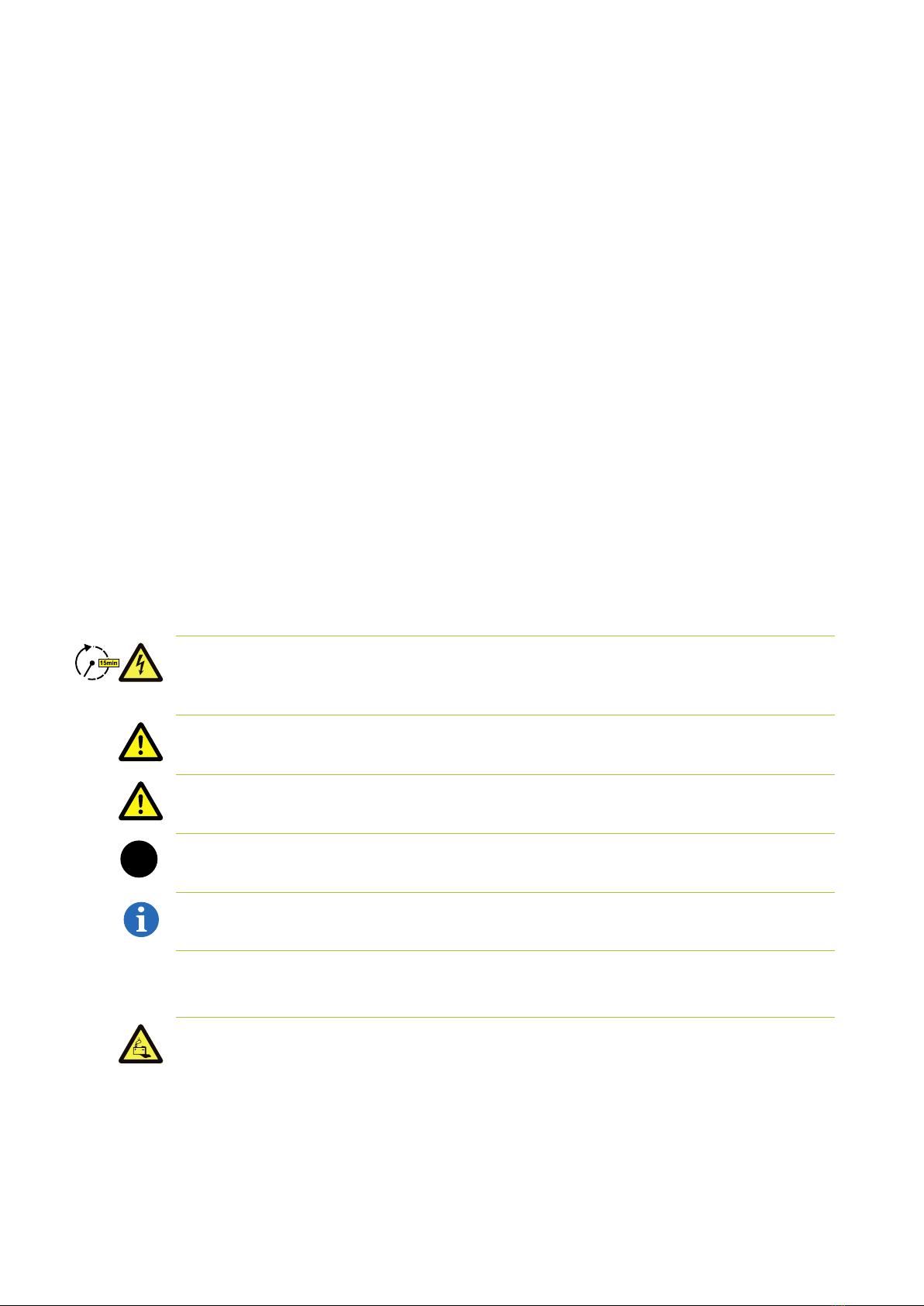
DANGER!
This symbol indicates that electric shock may result if you fail to follow the instruction, even when the
unit is disconnected from the utility grid, as a voltage-free state only occurs after a time delay.
DANGER!
This symbol indicates that death or serious injury may result if you fail to follow the instruction.
CAUTION!
This symbol indicates that injury may result if you fail to follow the instruction.
WARNING!
This symbol indicates that material damage may result if you fail to follow the instruction.
NOTE:
This symbol indicates information relating to use of the device.
Symbols on the unit
The following types of warning, prohibition and mandatory symbols are also used on the unit:
CAUTION! RISK OF CHEMICAL BURNS
If the battery is damaged and a fault occurs, this may result in electrolyte escaping and the formation
of hydrofluoric acid in small concentrations and quantities, among other effects. Contact with these
liquids can lead to chemical burns.
•Do not subject the battery modules to violent impact.
•Do not open, disassemble or mechanically alter the battery modules.
•If there is contact with the electrolyte, rinse the affected area immediately with water and promptly
seek medical attention.
STOP

Important InformatIon about thIs manual 5
© TESVOLT We reserve the right to make technical changes! RD.TI.026.E.ENG_Installation_Manual_TSHV70OD_v.B.01 Last revised 01/2021
CAUTION! RISK OF EXPLOSION
Improper handling or fire can cause lithium battery cells to ignite or explode and cause serious inju-
ries.
•Do not install or operate the battery modules in potentially explosive areas or in areas with high
humidity.
•Store the battery modules in a dry area and within the temperature ranges specified in the data
sheet.
•Do not open, drill through or drop the battery cells or modules.
•Do not expose the battery cells or modules to high temperatures.
•Do not throw the battery cells or modules into a fire.
•In case of fire, use CO2fire extinguishers if the fire comes from the battery. In case of fire in the
vicinity of the battery, use an ABC fire extinguisher.
•Do not use defective or damaged battery modules.
CAUTION HOT SURFACE!
In the event of malfunction, components can become very hot and cause serious injury if touched.
•Switch the storage system off immediately if it is defective.
•Take particular care if malfunctions or defects become apparent when handling the unit.
NO NAKED FLAMES!
Handling naked flames and sources of ignition in the immediate vicinity of the storage system is pro-
hibited.
DO NOT INSERT OBJECTS INTO OPENINGS ON THE STORAGE SYSTEM’S CASING!
No objects, such as screwdrivers, may be inserted through openings in the casing of the storage sys-
tem.
WEAR SAFETY GOGGLES!
Wear safety goggles when working on the unit.
FOLLOW THE MANUAL!
It is imperative that you follow the Installation and Operating Manual when working on and operating
the unit.
. GENERAL SAFETY INFORMATION
Danger! Danger of death if the safety information is not followed!
Improper use can lead to fatal injuries. Any person tasked with working on the system must have read
and understood this manual and, in particular, the section “2 Safety” on page 7 et seq. All the
safety instructions must be followed under all circumstances.
Everyone who works on the TESVOLT TSHV 70 Outdoor must follow the specifications in this manual.
This manual cannot describe every conceivable situation, and for this reason the applicable standards
and corresponding occupational health and safety regulations always take priority.
In addition, installation may also involve residual hazards under the following circumstances:
•Installation is not carried out properly.
•Installation is carried out by personnel who have not received the relevant training or instruction.
•The safety information provided in this manual is not followed.

6Important InformatIon about thIs manual
© TESVOLT We reserve the right to make technical changes! RD.TI.026.E.ENG_Installation_Manual_TSHV70OD_v.B.01 Last revised 01/2021
. LIMITATION OF LIABILITY
TESVOLT GmbH assumes no liability for personal injury, damage to property, damage to the product
and follow-on damage attributable to the following causes:
•Non-compliance with this manual,
•Improper use of the product,
•Repairs, opening the cabinet and other actions performed on or with the product by unauthorised
and/or unqualified personnel,
•Use of non-approved spare parts.
Unauthorised modifications or technical changes to the product are forbidden
. APPROPRIATE USE
The TESVOLT TS HV 70 Outdoor is a modular battery storage system based on lithium-ion technology.
The components were built in accordance with the current state of the art in technology and prod-
uct-specific standards.
The TESVOLT TS HV 70 Outdoor has been designed for operation with the Sunny Tripower Storage 60
(SMA STPS 60) three-phase battery inverter manufactured by SMA. Any other use must be agreed
with the manufacturer and, if necessary, with the local energy supply company.
It may be operated outdoors or indoors. Depending on the variant and design, the
TESVOLT TS HV 70 Outdoor works within an ambient temperature range of -33°C to 55°C and at a maxi-
mum humidity of 85%. The battery cabinet may not be exposed to corrosive environments.
When installing the battery storage system, ensure that it is standing on a sufficiently dry, horizontal
and flat surface with sufficient load-bearing capacity. The inclination of the installation area may not
exceed 0.5%. Irregularities must be < 0.25% in accordance with DIN 18202. The system is to be installed
in the agreed location and may not be subsequently moved. The altitude of the installation location may
not be higher than 2,000 m above sea level without approval in writing from the manufacturer.
In regions subject to flooding or in topographical depressions, care must be taken to ensure that the
battery storage system is installed in a suitably elevated location and is protected against contact with
water.
The outdoor cabinet may not be installed in the immediate vicinity of fire loads.
Furthermore, a risk assessment in accordance with DIN EN 62305-2 is required for the installation site
to assess the lightning protection measures and, if necessary, to install lightning protection.
Care must be taken at the installation site to ensure that external mechanical loading (e.g. from being
driven into by vehicles or from falling trees) cannot occur.
Adherence to the specifications in this manual also forms part of appropriate use.
The TESVOLT TS HV 70 Outdoor may not be used:
•For mobile use on land or in the air (it may only be used on water in agreement with, and with the
written consent of, the manufacturer),
•For use with medical equipment,
•As a UPS system.
. GUARANTEE
The current guarantee conditions can be downloaded from the internet by visiting www.tesvolt.com.

safety 7
© TESVOLT We reserve the right to make technical changes! RD.TI.026.E.ENG_Installation_Manual_TSHV70OD_v.B.01 Last revised 01/2021
. PREREQUISITES FOR INSTALLERS
The locally applicable regulations and standards are to be adhered to for all work.
The installation of the battery storage system may only be carried out by qualified electricians who
have the following qualifications:
•Training in dealing with hazards and risks associated with installing and operating electrical equip-
ment, systems and batteries,
•Training in installing and commissioning electrical equipment,
•Knowledge of and compliance with the locally applicable technical connection requirements, stand-
ards, directives, regulations and laws,
•Knowledge of handling lithium-ion batteries (transport, storage, disposal, sources of danger),
•Knowledge of and compliance with this Installation and Operating Manual and other applicable docu-
ments,
•Successful participation in TESVOLT HV 70 Outdoor certification training (information about the
training courses can be found at www.tesvolt.com. For further information, please send an email to
academy@tesvolt.com).
SAFETY
DANGER! Lethal electric shock from damaged components or short circuits
Bridging the battery poles causes a short circuit that results in a flow of electrical current. A short cir-
cuit of this type should be avoided under all circumstances. For this reason, follow these instructions:
•Use insulated tools and insulated gloves.
•Do not place any tools or metal components on the battery modules or the APU HV1000-S.
•Always remove watches, rings and other metal objects when working with the batteries.
•Do not install or operate the battery storage system in explosive areas or areas with high humidity.
•When working on the battery storage system, switch off all voltage supplies first to the charge con-
troller, then to the battery, and ensure that they cannot be switched on again.
DANGER! Chemical burns and poisoning due to electrolyte or poisonous gases
During normal operation, no electrolyte can escape from the battery and no poisonous gases can
form. Despite careful design, damage to the battery in the event of a fault can result in escaping elec-
trolyte or small concentrations and quantities of toxic gases, organic solvent gases and hydrofluoric
acid. For this reason, please follow these instructions:
•Do not subject the battery modules to violent impact.
•Do not open, disassemble or mechanically alter the battery modules.
If there is contact with the electrolyte, rinse the affected area immediately with water and promptly
seek medical attention.

8safety
© TESVOLT We reserve the right to make technical changes! RD.TI.026.E.ENG_Installation_Manual_TSHV70OD_v.B.01 Last revised 01/2021
DANGER! Improper handling can result in life-threatening burns
Lithium battery cells can ignite if handled incorrectly. For this reason, ensure that you adhere to the
following instructions for handling lithium battery cells:
•Do not install or operate the battery modules in explosive areas or in areas with high humidity.
•Store the battery modules in a dry area and within the temperature ranges specified in the data
sheet.
•Do not open, drill through or drop the battery cells or modules.
•Do not expose the battery cells or modules to high temperatures.
•Do not throw the battery cells or modules into a fire.
•In case of fire, use CO2 fire extinguishers if the fire comes from the battery. In case of fire in the
vicinity of the battery, use an ABC fire extinguisher.
•Do not use defective or damaged battery modules.
DANGER! Danger of death due to misuse
Any use that extends beyond or deviates from appropriate use of the battery storage system can lead
to significant hazards.
DANGER! Danger of death due to unqualified operators
Incorrect handling of the battery storage system can result in significant hazards for the operator. For
this reason, any action that requires the battery cabinet to be opened may only be carried out by quali-
fied specialists in accordance with the instructions in section “1.7 Prerequisites for installers” on page
7.
ATTENTION! Incorrect use can cause damage to the battery cells
•Do not expose battery cells or modules to rain and do not immerse them in liquids.
•Do not expose battery cells to corrosive environments (e.g. ammonia, salt).
•Do not use any other battery inverters apart from the SMA STPS 60.
•Commission battery storage systems within six months of delivery at the latest.
STOP

preparatIon 9
© TESVOLT We reserve the right to make technical changes! RD.TI.026.E.ENG_Installation_Manual_TSHV70OD_v.B.01 Last revised 01/2021
PREPARATION
. TOOLS REQUIRED:
TOOL USE
5–30 Nm torque wrench with 10 and 13 mm sockets, long
8 mm hexagon socket screwdriver (recommended minimum
length: 120 mm in total)
For tightening the grounding connections and the AC and
DC connecting cables to the SMA STPS 60 battery inverter,
among other things
TX 25/30 Torx screwdriver For fastening the floor outlet cover
PH 3 cross-head screwdriver Fastening the battery modules and APU HV1000-S in the
battery cabinet
35 mm² to 50 mm² crimping tool For crimping the wire-end ferrules for the DC connecting cable
Voltmeter (min. 1,000 VDC) Measuring the power supply and battery voltages (up to
1000 VDC) and testing the battery modules’ state of charge
Crane (> 400 kg capacity) For transporting the battery cabinet and installing the battery
cabinet in its final installation site
. MATERIALS TO BE PROVIDED BY THE CUSTOMER
DESCRIPTION USE
Grounding rods or ring grounding Potential equalisation
e.g. concrete, crushed stone, gravel Creation of the substrate and filling the base
Hollow pipes and cables for laying below ground level. AC supply line (5 x 35 to 50 mm2), network, DC wiring for
master/slave (2 x 35 to 50 mm2)
Outdoor distribution enclosure with provision for installation
space
Janitza power measurement, transformer measurement, pe-
ripheral equipment and BatBreaker for master/slave system
. TRANSPORT TO THE END CUSTOMER
Transport regulations and safety information
All the requirements set down in the German Ordinance on the Transport of Dangerous Goods by
Road, Rail and Inland Waterways (GGVSEB) and the European Agreement Concerning the International
Carriage of Dangerous Goods by Road (ADR) must be adhered to.
•The battery modules may only be transported by the manufacturer or by a forwarding agency
engaged by the manufacturer. Should transport on public roads nevertheless be necessary, this
may only be carried out by personnel who have received appropriate training and instruction. This
instruction is to be documented and carried out periodically.
•Smoking is prohibited in the vehicle during the transport journey, and also in the immediate vicinity
during loading and unloading.
•Two tested Class D metal fire extinguishers (minimum capacity: 2 kg) and equipment for dangerous
goods in accordance with the ADR are to be carried in the vehicle.
•The freight carrier is prohibited from opening the outer packaging of the battery module.
DANGER! Risk of injury due to improper transport in a vehicle
Improper transport and/or inadequate transport locks can cause the load to slide or topple over, lead-
ing to injuries. Position the cabinet vertically and in such a way that it cannot slide around in the vehi-
cle, and use securing straps to prevent it from toppling over and sliding.
CAUTION! Risk of injury due to tilting battery cabinet
Do not tilt the cabinet. The cabinet weighs approx. 400 kg and may topple over if tilted excessively,
causing injuries or material damage.

10 preparatIon
© TESVOLT We reserve the right to make technical changes! RD.TI.026.E.ENG_Installation_Manual_TSHV70OD_v.B.01 Last revised 01/2021
CAUTION! Risk of injury if safety shoes are not worn when the cabinet is being transported
If hazards occur, injuries such as crushing injuries can occur due to the components’ heavy self-weight
when the cabinet or battery modules is/are being transported. For this reason, all individuals involved
are to wear safety shoes with protective toe caps.
CAUTION!
Please also follow the safety information in section “3.4 Transport at the end customer‘s site” on page
10, especially when loading and unloading.
WARNING! Risk of damage to the battery storage system during transport with installed battery
modules
Transporting the cabinet with battery modules installed causes damage to the battery storage system.
The battery modules and battery cabinet must therefore always be transported separately from each
other. Never move a battery cabinet once fitted with battery modules, even by suspending it using a
lifting device.
. TRANSPORT AT THE END CUSTOMER‘S SITE
CAUTION! Risk of injury due to incorrect transport of the battery modules
Battery modules are heavy (36 kg) and can cause injuries if they topple over or slide around. Ensure
that transport is carried out safely and that only suitable means of transport are used.
CAUTION! Risk of injury due to the battery cabinet toppling over during transport
Do not tilt the cabinet. The cabinet weighs approx. 400 kg and may topple over if tilted, causing injuries
or material damage.
CAUTION! Risk of injury due to crushing when the cabinet is being transported
Safety shoes with protective toe caps must be worn when the battery cabinet is being transported.
CAUTION! Risk of injury from sharp edges and metal panels on the battery cabinet
Wear protective gloves when transporting the unpacked battery cabinet and during installation to
avoid cuts from sharp edges on the metal panels.
ATTENTION! Risk of damage to the battery storage system during transport with installed battery
modules
Transporting the battery cabinet with battery modules installed causes damage to the battery storage
system. The battery modules and battery cabinet must therefore always be transported separately
from each other. Never move a battery cabinet once fitted with battery modules, even by suspending it
using a lifting device.
NOTE: Transport by at least three people
We recommend using a suitable lifting device. Caution: Do not damage the casing!
The individual components of the TS HV 70 Outdoor can weigh up to 400 kg and are therefore unsuita-
ble for transport by one person. We recommend that at least three people install the system using a
crane or other suitable lifting device.
No more than five battery modules may be stored on top of each other.
STOP
STOP

preparatIon 11
© TESVOLT We reserve the right to make technical changes! RD.TI.026.E.ENG_Installation_Manual_TSHV70OD_v.B.01 Last revised 01/2021
Figure 3.1 Permissible and impermissible storage positions of a packaged battery module
. INSTALLATION SITE
Necessary prerequisites
Section “1.5 Appropriate use” on page 6 lists all the necessary prerequisites and conditions for
installing a TS HV 70 Outdoor.
When selecting the installation site, bear in mind the transport routes and the necessary site
clearance.
ATTENTION! Possible damage to the building due to excessive loads
When fully installed, the battery storage system weighs up to 1,101 kg. Ensure that the installation loca-
tion has sufficient load-bearing capacity. If in doubt, consult a structural engineer.
Dimensions and distances
Both diagrams: view from above
FoundationSpace requirements
All measurements in cm.
10
10
173.5
21
511.5
31
93.5
73.5
170 20
27060
Assembly allowanceRequired space
(incl. installation)
Fastening points base
4 x M12 threaded inserts or M12 threaded rods
(protruding length: min. 30 mm; max. 70 mm)
Position/size of the floor outlet
The exact foundation size and depth depends on the‚
cabinet and site conditions.
(For example: floor conditions, cabinet mass, etc.)
This should be determined by a structural engineer
on site.
FoundationSpace requirements
All measurements in cm.
10
10
21
5
31
170 20
27060
Assembly allowanceRequired space
(incl. installation)
Position/size of the floor outlet
Required cabinet footprint
153.5
STOPSTOP

12 teChnICal data
© TESVOLT We reserve the right to make technical changes! RD.TI.026.E.ENG_Installation_Manual_TSHV70OD_v.B.01 Last revised 01/2021
TECHNICAL DATA
. BATTERY CABINET SMA SUNNY TRIPOWER STORAGE SMA STPS
The battery storage system TESVOLT TS HV70 Outdoor has been optimised for use with the
SMA STPS 60 three-phase battery inverter. The overall system is perfectly coordinated to the needs of
trade and industry. The battery storage system can be used for an extremely wide range of applica-
tions thanks to the flexible energy management provided by the SMA Inverter Manager and the high
C-rate of the TESVOLT battery storage system. Projects up to the megawatt range can be implemented
with this unit.
TECHNICAL DATA SMA STPS
Nominal charging power (AC) 60 kVA
Nominal discharging power (AC) 75 kVA
DC voltage range 575 to 1,000 V
Dimensions (HxWxD) 740 x 570 x 306mm
Max. efficiency 98.8 %
Self-consumption < 3W
Operating temperature -25°C to 60°C
Weight 77 kg
Protection class IP65 | NEMA 3R
Communication Modbus TCP/IP
Topology Transformer-free
Guarantee 5 years Figure 4.1 SMA STPS 60 with SMA Inverter Manager
. TESVOLT TS HV OUTDOOR
TESVOLT TS HV OUTDOOR TECHNICAL DATA
Energy (14 | 16 battery modules) 67kWh | 76kWh
C-rate 1C
Cell Lithium NMC prismatic (Samsung SDI)
Max. charging/discharging current 94 A
Cell balancing Active Battery Optimizer
Cycles expected at 100 % DoD | 70 % EoL | 23°C +/- 5°C 6,000 (1C/1C) or 8,000 (0.5 C/0.5C)
Efficiency (battery) Up to 98 %
Self-consumption (standby) 5W (without battery inverter)
Operating voltage 666 V to 930 V
Ambient temperature -33°C to 55°C1, 2
Humidity < 85 % (non-condensing)
Altitude of installation site <2,000 m above sea level
Weight
Total < 1,020 kg | 1,101 kg1
Battery module 36kg
Battery cabinet <280 kg1
Dimensions (HxWxD) 1,945x 1,989x 1,030 mm1
Certificates/standards Cell IEC 62619, UL 1642, UN 38.3
Battery module CE,UN 38.3, IEC 62619, IEC 61000-6-1/2/3/4, German Battery Act 2006/66/EC
Battery cabinet DIN EN 62208, DIN EN 62368-1, DIN EN 60950-1, DIN EN 61439,
IEC 62262-IK10 GR-487-CORE, R3-40/41/42/43/44/59/192/204/207
Guarantee 10-year performance guarantee, 5-year system guarantee
Recycling TESVOLT offers free return of batteries from Germany
Protection class IP 55, NEMA 3/3R
Battery specification as per DIN EN 62620:2015 IMP47/175/127/[14S]E/-20+60/90
1Depending on design | 2SMA STPS 60: -25°C to 60°C

battery storage system ts hV 70 outdoor 13
© TESVOLT We reserve the right to make technical changes! RD.TI.026.E.ENG_Installation_Manual_TSHV70OD_v.B.01 Last revised 01/2021
BATTERY STORAGE SYSTEM TS HV OUTDOOR
. VARIANTS AND EQUIPMENT OF TS HV OUTDOOR
Air conditioners
Two designs with air conditioners are available for the TS HV 70 Outdoor depending on the climatic
conditions. The only difference is the number of air conditioners. There are no other differences in the
equipment. An additional, second heating unit can be ordered for both variants as an option.
MEDIUM PREMIUM
Number of air conditioners 1 2
Ambient temperature 1x heating unit -28°C to 40°C -33°C to 55°C
2x heating units -33°C to 40°C -33°C to 55°C
Noise level max. 65 dB (A) max. 68 dB (A)
Master/slave designs
The various master/slave variants differ in terms of their equipment in the battery inverter, the com-
munication and the measuring and control technology.
Please note that the master/slave systems always require at least one BatBreaker.
Further information on the master/slave systems is available in section “10.2 Expanding capacity using
additional TS HV 70 Outdoor units” on page 46.
SCOPE OF DELIVERY MASTER ADMIN MASTER SLAVE
SMA STPS 60 ● ● –
SMA Inverter Manager ●– –
SMA Data Manager M ●– –
Janitza power quality analyser ●– –
BatBreaker ●* ●*–
Switch LAN 1 ●– –
Switch LAN 2 ●– –
24 V voltage supply ●– –
* only in master/slave systems

14 battery storage system ts hV 70 outdoor
© TESVOLT We reserve the right to make technical changes! RD.TI.026.E.ENG_Installation_Manual_TSHV70OD_v.B.01 Last revised 01/2021
. BATTERY CABINET AND ACCESSORIES
Battery cabinet TS HV 70 Outdoor (master admin) in factory configuration, without battery modules
Cover of the battery inverter
Fastening plate for the
battery inverter
A
I J
Special key for safety screwSafety screw with
accessories and tool
Cage nut with installation
aid
Pan head screw with plastic
washer
Installed concrete base
(delivered un-installed)
Safety key to battery cabinet
(top), key for cover (bottom)
R S
T
Switches, SMA Inverter Manager, SMA Data
Manager M
B
F
G
D E
C
C
C
H
O QP
K L
K.1
M N
L.1
M1
S
T

battery storage system ts hV 70 outdoor 15
© TESVOLT We reserve the right to make technical changes! RD.TI.026.E.ENG_Installation_Manual_TSHV70OD_v.B.01 Last revised 01/2021
. CABINET SCOPE OF DELIVERY
ITEM NUMBER DESCRIPTION
Master
admin
Master
Slave
A1 1 1 Battery cabinet TS HV70 Outdoor
B1 1 1 Battery management system APU HV1000-S (pre-installed)
C3 3 3 Cable retention rails (pre-installed)
D1 1 1 Connector panel (pre-installed, master 9-row, slave 5-row)
E1 0 | 1*–24 V voltage supply (pre-installed)
F1 | 2 1 | 2 1 | 2 Air conditioner with ventilation plate (medium | premium)
G1 1 1 Heating unit (pre-installed; second heating unit available as an option)
H1 1 1 Potential equalisation rails (pre-installed, different position on the slave unit in the centre of
the cabinet)
I1 1 – Cover for battery inverter (pre-installed, master designs only)
J1 1 – Fastening plate for battery inverter (pre-installed, master designs only)
K100 100 100 M6 cage nut (pre-installed)
K .1 1 1 1 L auxiliary tool for cage nut
L100 100 100 M6 x 16 flat head screw (cross-head)
L .1 100 100 100 M6 plastic washer
M4 4 4 M12 x 20 safety screw with rubber washer and seal
(replacement for ring screws, with anti-theft protection)
M .1 1 1 1 L socket for M12 safety screw
N1 1 1 Special hexagon socket screwdriver (for fixing screws on the base cover)
O2 1* – Switch (pre-installed, master designs only)
P1 – – SMA Inverter Manager (pre-installed, master designs only)
Q1 – – SMA Data Manager M (pre-installed, optional, master designs only)
R1 1 1 Concrete base (optional)
S3 3 3 Battery cabinet security key
T2 2 0 Inverter cover key (master designs only)
*Only for systems with an interconnection of 4 masters; the fourth master has a 24 V voltage supply and an additional switch

16 battery storage system ts hV 70 outdoor
© TESVOLT We reserve the right to make technical changes! RD.TI.026.E.ENG_Installation_Manual_TSHV70OD_v.B.01 Last revised 01/2021
. SETTING UP THE COMPONENTS
2.2
1
3.2
4.1
7.2
7.1
4.3
4.3
4.2
2.1
2.2
3.3
3.1
3.3
3.2
3
1 92
10 11 12
14 15
3.1
3.2
3.1
Battery cabinet (fitted)
Battery module incl. Active
Battery Optimizer (ABO)
Fuse
3 5 /12 5 A
APU connector kit HV1000 Module connector kit
HV1000
TS HV 70 Outdoor Installa-
tion and Operating Manual
TESVOLT USB-Stick Type plate
BatBreaker
Battery inverter SMA
Tripower Storage 60
2.1 2.2
2.3
9
9.1
13
Power measurement
Janitza UMG 604E-Pro

battery storage system ts hV 70 outdoor 17
© TESVOLT We reserve the right to make technical changes! RD.TI.026.E.ENG_Installation_Manual_TSHV70OD_v.B.01 Last revised 01/2021
. TS HV OUTDOOR SCOPE OF DELIVERY
ITEM NUMBER DESCRIPTION
Master
admin
Master
Slave
114 or 16 Battery module 4.8-1C-HV1000 incl. Active Battery Optimizer (ABO)
21 1 1 APU connector kit HV1000 Outdoor (from the APU to the 1st and 14th/16th battery module)
2.1 1 1 1 L DC connecting cable, 0.95 m – 35 mm² (RD to RD)
2.2 1 1 1 L DC connecting cable, 1.15 m – 35 mm² (BK to BK)
2.3 1 1 1 L CAT 6 patch cable, 0.30 m
31 1 1 Module connector kit HV1000 (extra pack with two extra cables each for 16 battery modules)
3.1 12 12 12 L DC connecting cable, 0.55 m – 35 mm2(RD to BK)
3.2 12 12 12 L CAT 6 patch cable, 0.30 m
3.3 12 12 12 L Rack balancing cable, 0.24 m
41 1 1 Cabinet connector kit HV1000 Outdoor
4.1 1 1 1 L DC connecting cable, 1.20 m – 35 mm2(pre-installed, RD to BK),
4.2 1 1 1 L CAT 6 patch cable, 1.00 m (pre-installed)
4.3 2 2 2 L Rack balancing cable, 1.10 m (pre--installed)
51 1 1 DC connector kit HV1000 Outdoor APU – BatBreaker (APU – terminal X3),
only for master/slave systems
5.1 1 1 1
L
DC connecting cable 35 mm
2
(pre-installed, with red wire-end ferrule and black plug)
5.2 111L DC connecting cable 35 mm2(pre-installed, with red wire-end ferrule and red plug)
61 1 0 DC connector kit HV1000 Outdoor BatBreaker– STPS (SMA STPS 60 – terminal X4), only
for master/slave systems, only for master/admin & master designs
6.1 1 1 0 L DC connecting cable 35 mm2(pre-installed, with two red wire-end ferrules)
6.2 1 1 0 L DC connecting cable 35 mm2(pre-installed, with two red wire-end ferrules)
71 1 0 DC connector kit HV1000 Outdoor APU – STPS only for single systems
7.1 1 1 0 L
DC connecting cable (+) 35 mm² (pre-installed, red wire-end ferrule on one end, red plug
on one end)
7.2 1 1 0 L
DC connecting cable (–) 35 mm² (pre-installed, red wire-end ferrule on one end, black plug on
one end)
81 1 0 Connector kit HV1000 Outdoor STPS (only for master/admin & master systems)
8.1 1 1 0 L AC connecting cable, 4x 35 mm² (pre-installed, red wire end ferrules on both ends)
8.2 110L Grounding cable, 50 mm² (pre-installed, green/yellow, blue wire end ferrules on both ends)
8.3 110L CAT 6 patch cable (pre-installed)
9333Tag fuse NH00 35 A
9.1 3 3 0 Tag fuse NH00 125 A
10 1 1 1 TESVOLT TS HV 70 Outdoor Installation and Operating Manual
11 1 1 1 TESVOLT USB-Stick
12 3 3 3 Type plateTS HV 70 Outdoor (pre-installed)
13 100Janitza UMG 604E-Pro power measurement
14 Op-
tional:
Op-
tional:
0BatBreaker 160-4X-HV1000 optional, for master/slave systems, included in scope of
delivery
15 110Battery inverter SMA STPS 60 nominal charging power 60 kVA, nominal discharging power
75 kVA, only for master designs, included in scope of delivery

18 battery storage system ts hV 70 outdoor
© TESVOLT We reserve the right to make technical changes! RD.TI.026.E.ENG_Installation_Manual_TSHV70OD_v.B.01 Last revised 01/2021
. CONNECTIONS AND STRUCTURE OF THE APU HVS
NO. DESIGNATION DESCRIPTION
1BATTERY − The battery’s DC connection for the negative pole (black)
2BATTERY + The battery’s DC connection for the positive pole (red)
324 V AUX PWR Connection not used on the TS HV70 Outdoor.
4E-STOP Two-pin plug for the optional connection of a dry emergency stop switch for quick shutdown
(pre-installed with the bridge on delivery)
5TERM CAN bus termination
TERM must be activated (ON) for the first and last CAN bus participants.
6CAN IN APU HV1000-S master/slave communication (input)
7CAN OUT APU HV1000-S master/slave communication (output)
8CAN SMA Connection not used on the TS HV70 Outdoor.
9LAN Modbus TCP/IP transmission for communication between battery and SMA Inverter Manager
10 ADDRESS Further information can be found in the section “Overview of all addressing options” on page 49.
11 BAT-COM Communication connection to the first battery module
12 CHARGER + DC connection for the SMA STPS 60 or BatBreaker for the positive pole (red)
13 CHARGER − DC connection for the SMA STPS 60 or BatBreaker for the negative pole (black)
14 GROUND Grounding connection (M6 thread bolt on the rear of the unit)
15 DISPLAY Display interface
16 MARKING Marking for activating and changing the display by tapping
17 SWITCH ON/OFF switch for the battery
18 APU fuse (F1) Fuse to protect the APU HV1000-S (2 A miniature fuse, 5 x 20 mm, time lag (T) according to DIN
41571-2, type: ESKA 521.020, 250 VAC). Operation is not possible with a defective fuse.
. CONNECTIONS AND STRUCTURE OF THE BATTERY MODULE
NO. DESIGNATION DESCRIPTION
19 − POLE Battery negative pole (black)
20 + POLE Battery positive pole (red)
21 RACK BALANCING IN Rack balancing (Input)
22 RACK BALANCING OUT Rack balancing (Output)
23 BAT-COM OUT Communication connection to
battery module (output)
24 BAT-COM IN Communication connection to
battery module (input)
BATTERY CHARGER
18 17
15
16
1 2 10 11 12 13
14
6 853
7 9
4
19
21
22
2423
20

battery storage system ts hV 70 outdoor 19
© TESVOLT We reserve the right to make technical changes! RD.TI.026.E.ENG_Installation_Manual_TSHV70OD_v.B.01 Last revised 01/2021
. CONNECTOR PANEL
Admin Master
Structure
30 31 32
33 34
35
38
3736
39
30 230 V AC service plugs
31 24 V voltage supply for communication components
32 N conductor terminal block
33 Circuit breakers
34 PE conductor terminal block
35 Surge arrester (for consumer)
36 Network connections (SMA STPS 60, APU HV1000-S)
37 X3/X4 terminals
38 NH00 isolator SMA STPS 60 and consumer
39 X1 through clamps
X3/X4 terminals
37
1 2 3 4
X3: max. 95 mm2
X4: max. 95 mm2
1X3 (+) BatBreaker input terminal to SMA STPS 60 (red)
2X3 (-) BatBreaker input terminal to SMA STPS 60 (black)
3X4 (+) APU output terminal to BatBreaker (white)
4X4 (-) APU output terminal to BatBreaker (blue)
Circuit breakers F3 …F8
1F3 circuit breaker for heating unit L
2F3 circuit breaker for heating unit N
3F4 circuit breaker for air conditioner 1 L
4F4 circuit breaker for air conditioner 1 N
5F5 circuit breaker for air conditioner 2 L
6F5 circuit breaker for air conditioner 2 N
7F6 RCB / CB service plugs L
8F6 RCB / CB service plugs N
9F7 circuit breaker for 24 V voltage supply / IVM
10 F7 spare circuit breaker for router
NH00 isolators F1, F2
38
4 5 61 2 3
1F1 SMA STPS 60 connection L1 (125 A)
2F1 SMA STPS 60 connection L2 (125 A)
3F1 SMA STPS 60 connection L3 (125 A)
4F2 outdoor load (35 A)
5F2 outdoor L2 load (35 A)
6F2 outdoor L3 load (35 A)
X1 through clamps
39
1 2 3 4 5 6 7 8 9
X1: max. 50 mm²
1AC connecting terminal L1
2AC connecting terminal L1
3AC connecting terminal L2
4AC connecting terminal L2
5AC connecting terminal L3
6AC connecting terminal L3
7AC connecting terminal N
8AC connecting terminal N
9AC connecting terminal PE
33
1 2 3 4 5 6 7 8 9 10

20 battery storage system ts hV 70 outdoor
© TESVOLT We reserve the right to make technical changes! RD.TI.026.E.ENG_Installation_Manual_TSHV70OD_v.B.01 Last revised 01/2021
Master
Structure
30 32
33 34
35
38
3736
39
30 230 V AC service plugs
32 N conductor terminal block
33 Circuit breakers
34 PE conductor terminal block
35 Surge arrester (for consumer)
36 Network connections (SMA STPS 60, HV1000-S APU)
37 X3/X4 terminals
38 NH00 isolator SMA STPS 60 and consumer
39 X1 through clamps
X3/X4 terminals
37
1 2 3 4
X3: max. 95 mm2
X4: max. 95 mm2
1X3 (+) BatBreaker input terminal to SMA STPS 60 (red)
2X3 (-) BatBreaker input terminal to SMA STPS 60 (black)
3X4 (+) APU output terminal to BatBreaker (white)
4X4 (-) APU output terminal to BatBreaker (blue)
Circuit breakers F3 …F8
1F3 circuit breaker for heating unit L
2F3 circuit breaker for heating unit N
3F4 circuit breaker for air conditioner 1 L
4F4 circuit breaker for air conditioner 1 N
5F5 circuit breaker for air conditioner 2 L
6F5 circuit breaker for air conditioner 2 N
7F6 RCB / CB service plugs L
8F6 RCB / CB service plugs N
9F7 circuit breaker for 24 V voltage supply / IVM
10 F7 spare circuit breaker for router
NH00 isolators F1, F2
38
4 5 61 2 3
1F1 SMA STPS 60 connection L1 (125 A)
2F1 SMA STPS 60 connection L2 (125 A)
3F1 SMA STPS 60 connection L3 (125 A)
4F2 outdoor L1 load (35 A)
5F2 outdoor L2 load (35 A)
6F2 outdoor L3 load (35 A)
X1 through clamps
39
1 2 3 4 5 6 7 8 9
X1: max. 50 mm²
1AC connecting terminal L1
2AC connecting terminal L1
3AC connecting terminal L2
4AC connecting terminal L2
5AC connecting terminal L3
6AC connecting terminal L3
7AC connecting terminal N
8AC connecting terminal N
9AC connecting terminal PE
33
1 2 3 4 5 6 7 8 9 10
Table of contents
Popular Batteries Pack manuals by other brands

POWER ON BOARD
POWER ON BOARD POCKET POWER instruction manual

Panasonic
Panasonic CF-VZSU26U operating instructions

Energizer
Energizer PP425 Product data sheet

MasterForce
MasterForce 252-8017 Operator's manual

Tripp Lite
Tripp Lite SmartPro BP48V60RT3U owner's manual

PowerWalker
PowerWalker LiFe Battery System 102-37 user manual