1
SLUUBZ5–November 2018
Submit Documentation Feedback Copyright © 2018, Texas Instruments Incorporated
bq40z80EVM Li-Ion Battery Pack Manager Evaluation Module
User's Guide
SLUUBZ5–November 2018
bq40z80EVM Li-Ion Battery Pack Manager Evaluation
Module
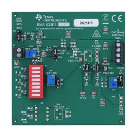
This evaluation module (EVM) is a complete evaluation system for the bq40z80 battery management
system. The EVM includes one bq40z80, two bq771807 secondary protectors, and a link to Microsoft®
Windows®based PC software. The circuit module includes one bq40z80 integrated circuit (IC), two
bq771807 secondary protectors, and all other onboard components necessary to monitor and predict
capacity, perform cell balancing, monitor critical parameters, protect the cells from overcharge, over-
discharge, short-circuit, and overcurrent in 2-, 3-, 4-, 5-, 6-, or 7-series cell Li-ion or Li-polymer battery
packs. The circuit module connects directly across the cells in a battery. The bq40z80EVM can use the
on-board EV2400 or an external EV2400 interface board and software to read the bq40z80 data registers,
program the chipset for different pack configurations, log cycling data for further evaluation, and evaluate
the overall functionality of the solution under different charge and discharge conditions.
Contents
1 Features....................................................................................................................... 2
1.1 Kit Contents.......................................................................................................... 2
1.2 Ordering Information ............................................................................................... 2
1.3 Documentation ...................................................................................................... 2
1.4 bq40z80 and bq771807 Circuit Module Performance Specification Summary............................. 2
2 bq40z80EVM Quick Start Guide........................................................................................... 3
2.1 Items Needed for EVM Setup and Evaluation .................................................................. 3
2.2 Software Installation................................................................................................ 3
2.3 EVM Connections................................................................................................... 4
2.4 Update Firmware.................................................................................................... 5
3 Battery Management Studio................................................................................................ 6
3.1 Registers Screen.................................................................................................... 6
3.2 Setting Programmable bq40z80 Options ........................................................................ 7
3.3 Calibration Screen.................................................................................................. 8
3.4 Chemistry Screen ................................................................................................. 10
3.5 Firmware Screen .................................................................................................. 11
3.6 Advanced Comm SMB Screen.................................................................................. 12
4 bq40z80EVM Circuit Module Schematic................................................................................ 14
4.1 Pre-Charge......................................................................................................... 15
4.2 Pre-Discharge...................................................................................................... 15
4.3 LED Control........................................................................................................ 15
4.4 Emergency Shutdown ............................................................................................ 15
4.5 Testing Fuse-Blowing Circuit .................................................................................... 15
5 Circuit Module Physical Layouts ......................................................................................... 16
5.1 Board Layout....................................................................................................... 16
5.2 bq40z80 RevBSchematic ........................................................................................ 22
6 bq40z80EVM Bill of Materials ............................................................................................ 24
7 Related Documentation from Texas Instruments ...................................................................... 28
List of Figures
1 bq40z80 Circuit Module Connection to Cells and System Load or Charger......................................... 4
2 Registers Screen ............................................................................................................ 6
3 Data Memory Screen........................................................................................................ 7
