6 Using the TPS65988EVM......................................................................................................................................................29
6.1 Powering the TPS65988EVM.......................................................................................................................................... 29
6.2 Firmware Configurations.................................................................................................................................................. 29
7 Connecting the EVM.............................................................................................................................................................30
7.1 Connecting to Various Devices........................................................................................................................................ 30
7.2 Debugging the EVM......................................................................................................................................................... 35
8 REACH Compliance..............................................................................................................................................................37
9 TPS65988EVM Schematic.................................................................................................................................................... 38
10 TPS65988EVM Board Layout.............................................................................................................................................51
11 TPS65988EVM Bill of Materials..........................................................................................................................................54
12 Revision History................................................................................................................................................................. 62
List of Figures
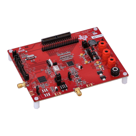
Figure 1-1. TPS65988EVM..........................................................................................................................................................1
Figure 1-2. TPS65988EVM Block Diagram................................................................................................................................. 2
Figure 5-1. TPS65988 Jumper Configuration.............................................................................................................................. 7
Figure 5-2. TPS65988 Jumper Configuration Net Names........................................................................................................... 7
Figure 5-3. TPS65987D Jumper Configuration........................................................................................................................... 8
Figure 5-4. TPS65987D Jumper Configuration Net Names........................................................................................................ 8
Figure 5-5. TPS65987S Jumper Configuration............................................................................................................................9
Figure 5-6. TPS65987S Jumper Configuration Net Names.......................................................................................................10
Figure 5-7. DisplayPort Source Schematic Block...................................................................................................................... 10
Figure 5-8. DisplayPort Source Block Diagram......................................................................................................................... 10
Figure 5-9. DisplayPort Source Receptacle...............................................................................................................................11
Figure 5-10. HRESET Push-Button (S1) Schematic..................................................................................................................11
Figure 5-11. HRESET Push-Button (S1)....................................................................................................................................11
Figure 5-12. SPI-MISO Pull Down Switch................................................................................................................................. 12
Figure 5-13. FTDI Dip Switch (S3) Schematic...........................................................................................................................12
Figure 5-14. FTDI Dip Switch (S3).............................................................................................................................................13
Figure 5-15. I2C and BusPower DIP Switch (S2)...................................................................................................................... 14
Figure 5-16. I2C DIP Switch (S2) Schematic.............................................................................................................................14
Figure 5-17. Barrel Jack (J1) Schematic................................................................................................................................... 15
Figure 5-18. Barrel Jack (J1)..................................................................................................................................................... 15
Figure 5-19. Barrel Jack Detect Schematic............................................................................................................................... 16
Figure 5-20. USB Type-B Receptacle (J11) Schematic.............................................................................................................16
Figure 5-21. USB (J11) Block Diagram......................................................................................................................................16
Figure 5-22. USB Type-B Receptacle (J11)...............................................................................................................................17
Figure 5-23. USB Type-C Receptacles (J2) Schematic.............................................................................................................18
Figure 5-24. USB Type-C Receptacles (J2).............................................................................................................................. 18
Figure 5-25. USB Micro-B Receptacle (J9) Schematic..............................................................................................................19
Figure 5-26. USB Micro-B Receptacle (J9)............................................................................................................................... 19
Figure 5-27. TP13 (5 V), TP8 (3.3 V), and TP12 (1.2 V)........................................................................................................... 20
Figure 5-28. Aardvark Connector (J10) Schematic................................................................................................................... 21
Figure 5-29. Aardvark Connector (J10)..................................................................................................................................... 21
Figure 5-30. TP10, TP11, TP15, TP16, TP17, TP18, TP9: GND Test Points............................................................................ 21
Figure 5-31. TP1, TP2, TP3 and TP4 – CC1 and CC2 Test Points........................................................................................... 22
Figure 5-32. TPS65988 BMC Data............................................................................................................................................22
Figure 5-33. VBUS Test Points: TP14....................................................................................................................................... 23
Figure 5-34. TPS65988 VBUS Voltage Transition..................................................................................................................... 23
Figure 5-35. A-Var, B-Var and System Power Test Points: TP7, TP6, and TP5........................................................................ 24
Figure 5-36. BoosterPack Headers (J3 and J4)........................................................................................................................ 25
Figure 5-37. MUX Control LEDs................................................................................................................................................ 26
Figure 5-38. HPD Port A/B LEDs...............................................................................................................................................26
Figure 5-39. PDO Port A/B LEDs.............................................................................................................................................. 27
Figure 7-1. Connecting EVM to Type-A Device......................................................................................................................... 30
Figure 7-2. Connecting EVM to USB Type-C Devices...............................................................................................................31
Figure 7-3. DRP CC1 and CC2 Toggling................................................................................................................................... 35
Figure 7-4. USB Type-C Connection and VBUS....................................................................................................................... 35
Figure 7-5. USB Type-C Connection and PD Negotiation......................................................................................................... 36
Figure 9-1. TPS65988EVM Block Diagram............................................................................................................................... 38
Figure 9-2. TPS65988EVM Processor Block.............................................................................................................................39
Figure 9-3. TPS65988EVM Power Path Block.......................................................................................................................... 40
Figure 9-4. TPS65988EVM Power Supply Block.......................................................................................................................41
www.ti.com Table of Contents
SLVUB62B – JUNE 2017 – REVISED NOVEMBER 2020
Submit Document Feedback
TPS65988 Evaluation Module 3
Copyright © 2020 Texas Instruments Incorporated
