TEXIO LSG SERIES Owner's manual

Front cover
PROGRAMMING MANUAL
ELECTRONIC LOAD
LSG SERIES
LSG-175 LSG-350 LSG-1050
B71-0428-11

■About a trademark, a registered trademark
A company name and the brand name mentioned in this instruction
manual are the trademark or the registered trademark of each
company or group in each country and region.
■About this instruction manual
When copying the part or all of contents of this instruction manual, seek
the copyright holder.
In addition, the specifications of the product and the contents of this
instruction manual are subject to change without notice for
improvement. Please check to our website for the latest version.
■ About Version of LSG Series
This manual will correspond to the Ver 1.27 the firmware of LSG series.
There is some difference from specifications of firmware Ver1.01.
Please refer to the change history of the appendix.

CONTENTS
1. INTERFACE OVERVIEW............................. 1
1-1. Front Panel Overview ..............................................1
1-2. Rear Panel Overview...............................................1
2. INTERFACE Configure............................... 2
2-1. Configuring the USB Interface..................................2
2-2. Configuring the RS-232C Interface...........................2
2-3. Configuring the GP-IB Interface ...............................3
2-4. RS-232C/USB Remote Control Function Check ........4
2-5. Using Realterm to Establish a Remote Connection....4
2-6. GP-IB Function Check .............................................6
3. COMMAND OVERVIEW .............................. 8
3-1. Command Syntax ....................................................8
4. COMMAND DETAILS.................................11
4-1. Common Commands ............................................. 11
4-1-1. *CLS .................................................................................................11
4-1-2. *ESE.................................................................................................11
4-1-3. *ESR.................................................................................................11
4-1-4. *IDN..................................................................................................12
4-1-5. *OPC.................................................................................................12
4-1-6. *RCL.................................................................................................12
4-1-7. *RST.................................................................................................13
4-1-8. *SAV.................................................................................................13
4-1-9. *SRE.................................................................................................13
4-1-10. *STB ...............................................................................................14
4-1-11. *TRG...............................................................................................14
4-1-12. *TST................................................................................................14
4-2. Input Commands...................................................15
4-2-1. :ABORt..............................................................................................15
4-2-2. :INITiate:CONTinuous.......................................................................15
4-2-3. :INITiate[:IMMediate].........................................................................15
4-2-4. :INPut................................................................................................16
4-2-5. [:INPut]:SHORt..................................................................................16
4-2-6. :INPut:MODE....................................................................................17
4-2-7. :INPut[:STATe]:TRIGered.................................................................17
4-3. Measurement Commands ......................................18
4-3-1. :MEASure:CURRent.........................................................................18
4-3-2. :MEASure:ETIMe..............................................................................18
4-3-3. :MEASure:POWer.............................................................................18
4-3-4. :MEASure:VOLTage.........................................................................18

4-4. Configure Subsystem Commands...........................19
4-4-1. [:CONFigure]:OCP............................................................................19
4-4-2. [:CONFigure]:OPP............................................................................19
4-4-3. [:CONFigure]:UVP ............................................................................20
4-4-4. [:CONFigure]:OVP............................................................................20
4-4-5. [:CONFigure]:SSTart.........................................................................21
4-4-6. [:CONFigure]:VON............................................................................21
4-4-7. [:CONFigure]:VDELay.......................................................................22
4-4-8. :CONFigure:RESPonse....................................................................22
4-4-9. [:CONFigure]:CNTime.......................................................................23
4-4-10. [:CONFigure]:COTime ....................................................................23
4-4-11. [:CONFigure]:CRUnit ......................................................................23
4-4-12. :CONFigure:DYNamic.....................................................................24
4-4-13. :CONFigure:MEMory ......................................................................24
4-4-14. :CONFigure:SHORt ........................................................................25
4-4-15. [:CONFigure]:GNG:SPECTest........................................................25
4-4-16. [:CONFigure]:GNG:DTIMe..............................................................26
4-4-17. [:CONFigure]:GNG:Mode................................................................26
4-4-18. [:CONFigure]:GNG[:PASS].............................................................27
4-4-19. [:CONFigure]:GNG:H......................................................................27
4-4-20. [:CONFigure]:GNG:L.......................................................................27
4-4-21. [:CONFigure]:GNG:C......................................................................28
4-5. Parallel Commands ...............................................29
4-5-1. [:CONFigure]:PARallel......................................................................29
4-6. Step Commands....................................................29
4-6-1. [:CONFigure]:STEP:CC ....................................................................29
4-6-2. [:CONFigure]:STEP:CCH..................................................................30
4-6-3. [:CONFigure]:STEP:CCM .................................................................30
4-6-4. [:CONFigure]:STEP:CCL ..................................................................31
4-6-5. [:CONFigure]:STEP:CR ....................................................................31
4-6-6. [:CONFigure]:STEP:CRH..................................................................31
4-6-7. [:CONFigure]:STEP:CRM .................................................................32
4-6-8. [:CONFigure]:STEP:CRL ..................................................................32
4-6-9. [:CONFigure]:STEP:CV ....................................................................33
4-6-10. [:CONFigure]:STEP:CVH................................................................33
4-6-11. [:CONFigure]:STEP:CVL ................................................................34
4-6-12. [:CONFigure]:STEP:CP ..................................................................34
4-6-13. [:CONFigure]:STEP:CPH................................................................35
4-6-14. [:CONFigure]:STEP:CPM ...............................................................35
4-6-15. [:CONFigure]:STEP:CPL ................................................................36
4-7. External Control Commands ..................................36
4-7-1. [:CONFigure]:EXTernal[:CONTrol]....................................................36
4-7-2. [:CONFigure]:EXTernal:LOAdonin....................................................37
4-7-3. [:CONFigure]:EXTernal:SYNC..........................................................37
4-8. Mode Subsystem Commands................................. 38
4-8-1. :MODE..............................................................................................38
4-8-2. [:MODE]:CRANge.............................................................................38

4-8-3. [:MODE]:VRANge.............................................................................39
4-8-4. [:MODE]:RESPonse..........................................................................39
4-8-5. [:MODE]:DYNamic............................................................................39
4-9. Current Subsystem Commands..............................40
4-9-1. :CURRent[:VA]..................................................................................40
4-9-2. :CURRent[:VA]:TRIGgered...............................................................40
4-9-3. :CURRent:VB....................................................................................41
4-9-4. :CURRent:SRATe.............................................................................41
4-9-5. :CURRent:L1.....................................................................................42
4-9-6. :CURRent:L2.....................................................................................42
4-9-7. :CURRent:SET..................................................................................43
4-9-8. :CURRent:LEVel...............................................................................43
4-9-9. :CURRent:RISE................................................................................44
4-9-10. :CURRent:FALL..............................................................................44
4-9-11. :CURRent:T1 ..................................................................................45
4-9-12. :CURRent:T2 ..................................................................................45
4-9-13. :CURRent:FREQuency...................................................................46
4-9-14. :CURRent:DUTY.............................................................................46
4-10. Resistance Subsystem Commands.......................47
4-10-1. :RESistance[:VA] ............................................................................47
4-10-2. :RESistance[:VA]:TRIGgered..........................................................47
4-10-3. :RESistance:VB ..............................................................................48
4-10-4. :RESistance:SRATe........................................................................48
4-10-5. :RESistance:L1...............................................................................49
4-10-6. :RESistance:L2...............................................................................49
4-10-7. :RESistance:SET............................................................................50
4-10-8. :RESistance:LEVel..........................................................................50
4-10-9. :RESistance:RISE...........................................................................51
4-10-10. :RESistance:FALL.........................................................................51
4-10-11. :RESistance:T1.............................................................................52
4-10-12. :RESistance:T2.............................................................................52
4-10-13. :RESistance:FREQuency..............................................................53
4-10-14. :RESistance:DUTY .......................................................................53
4-10-15. :CONDuctance[:VA]......................................................................54
4-10-16. :CONDuctance [:VA]:TRIGgered ..................................................54
4-10-17. :CONDuctance:VB........................................................................55
4-10-18. :CONDuctance:L1.........................................................................55
4-10-19. :CONDuctance:L2.........................................................................56
4-10-20. :CONDuctance:SET......................................................................56
4-11. Voltage Subsystem Commands ............................57
4-11-1. :VOLTage[:VA]................................................................................57
4-11-2. :VOLTage:VB..................................................................................57
4-12. Power Subsystem Commands..............................58
4-12-1. :POWer[:VA] ...................................................................................58
4-12-2. :POWer:VB .....................................................................................58
4-12-3. :POWer:L1......................................................................................59
4-12-4. :POWer:L2......................................................................................59

4-12-5. :POWer:SET...................................................................................60
4-12-6. :POWer:LEVel.................................................................................60
4-12-7. :POWer:T1......................................................................................61
4-12-8. :POWer:T2......................................................................................61
4-12-9. :POWer:FREQuency.......................................................................62
4-12-10. :POWer:DUTY ..............................................................................62
4-13. Program Commands ............................................63
4-13-1. : PROGram.....................................................................................63
4-13-2. [:PROGram]:CHAin.........................................................................64
4-13-3. [:PROGram]:CHAin:P2P.................................................................64
4-13-4. [:PROGram]:CHAin[:RECall]:DEFault.............................................65
4-13-5. [:PROGram]:CHAin:STARt .............................................................65
4-13-6. :PROGram:MEMory........................................................................65
4-13-7. :PROGram:OFFTime......................................................................66
4-13-8. :PROGram:ONTime........................................................................66
4-13-9. :PROGram:PFTime.........................................................................67
4-13-10. :PROGram[:RECall]:DEFault........................................................67
4-13-11. :PROGram:RUN ...........................................................................67
4-13-12. :PROGram:SAVE..........................................................................68
4-13-13. :PROGram:STARt.........................................................................68
4-13-14. :PROGram:STATe........................................................................68
4-13-15. :PROGram:STEP..........................................................................69
4-13-16. :PROGram:STIMe.........................................................................69
4-14. Normal sequence Commands...............................70
4-14-1. :NSEQuence...................................................................................70
4-14-2. :NSEQuence:CHAin........................................................................71
4-14-3. :NSEQuence[:DELet]:ALL...............................................................72
4-14-4. :NSEQuence:EDIT..........................................................................72
4-14-5. :NSEQuence:LAST.........................................................................73
4-14-6. :NSEQuence:LLOAD......................................................................73
4-14-7. :NSEQuence:LOOP........................................................................74
4-14-8. :NSEQuence:MEMO.......................................................................74
4-14-9. :NSEQuence:MODE .......................................................................74
4-14-10. :NSEQuence:NUMBer..................................................................75
4-14-11. :NSEQuence:RANGe....................................................................75
4-14-12. :NSEQuence:SAVE ......................................................................76
4-14-13. :NSEQuence:STARt .....................................................................76
4-14-14. :NSEQuence:STATe.....................................................................77
4-15. Fast sequence Commands...................................77
4-15-1. :PFSEQuence.................................................................................77
4-15-2. :FSEQuence[:DELet]:ALL...............................................................79
4-15-3. :FSEQuence:EDIT..........................................................................79
4-15-4. :FSEQuence[:EDIT]:FILL................................................................79
4-15-5. :FSEQuence:LAST .........................................................................80
4-15-6. :FSEQuence:LLOAD.......................................................................81
4-15-7. :FSEQuence:LOOP ........................................................................81
4-15-8. :FSEQuence:MEMO .......................................................................82

4-15-9. :FSEQuence:MODE........................................................................82
4-15-10. :FSEQuence:RANGe....................................................................82
4-15-11. :FSEQuence:RPTStep..................................................................83
4-15-12. :FSEQuence:SAVE.......................................................................84
4-15-13. :FSEQuence:TBASe.....................................................................84
4-15-14. :FSEQuence:STATe .....................................................................84
4-16. OCP Test Commands...........................................85
4-16-1. :OCP:STATe...................................................................................85
4-16-2. :OCP:EDIT[:CHANnel]....................................................................85
4-16-3. :OCP:[CHANnel]:NUMBer ..............................................................86
4-16-4. :OCP:[CHANnel]:RANGe................................................................86
4-16-5. :OCP:[CHANnel]:STARt..................................................................87
4-16-6. :OCP:[CHANnel]:END.....................................................................87
4-16-7. :OCP:[CHANnel]:STEP:CURRent...................................................87
4-16-8. :OCP:[CHANnel]:LAST ...................................................................88
4-16-9. :OCP:[CHANnel]:STEP:TIME .........................................................88
4-16-10. :OCP:[CHANnel]:DELay ...............................................................88
4-16-11. :OCP:[CHANnel]:TRIGger.............................................................89
4-16-12. :OCP:CHANnel:STATus ...............................................................89
4-16-13. :OCP:RESult.................................................................................89
4-16-14. :OCP:SAVE...................................................................................90
4-16-15. :OCP:RUN ....................................................................................90
4-17. Utility Commands ................................................90
4-17-1. :UTIlity:ALARm ...............................................................................90
4-17-2. :UTIlity:BRIghtness.........................................................................90
4-17-3. :UTIlity:CONTrast............................................................................91
4-17-4. :UTIlity:GNG....................................................................................91
4-17-5. :UTIlity:KNOB..................................................................................91
4-17-6. :UTIlity:LANGuage..........................................................................92
4-17-7. :UTIlity:LOAD..................................................................................92
4-17-8. :UTIlity:SPEAker.............................................................................93
4-17-9. :UTIlity:SYStem...............................................................................93
4-17-10. :UTIlity:TIMe..................................................................................94
4-17-11. :UTIlity:UNReg..............................................................................94
4-18. Interface Commands ...........................................95
4-18-1. :UTIlity:BRATe................................................................................95
4-18-2. :UTIlity:INTerface............................................................................95
4-18-3. :UTIlity:PARity.................................................................................96
4-18-4. :UTIlity:SBIT....................................................................................96
4-19. File Commands ...................................................96
4-19-1. :FACTory[:RECall] ..........................................................................96
4-19-2. :MEMory:RECall .............................................................................97
4-19-3. :MEMory:SAVE...............................................................................97
4-19-4. :PREset:RECall...............................................................................97
4-19-5. :PREset:SAVE................................................................................97
4-19-6. :SETup:RECall................................................................................98
4-19-7. :SETup:SAVE .................................................................................98

4-19-8. :USER[:DEFault]:RECall.................................................................98
4-19-9. :USER[:DEFault]:SAVE ..................................................................98
4-20. SCPI Status Commands.......................................98
4-20-1. :SYSTem:ERRor.............................................................................98
4-20-2. :STATus:PRESet............................................................................99
4-21. Csummary Status Commands ..............................99
4-21-1. :STATus:CSUMmary:CONDition ....................................................99
4-21-2. :STATus:CSUMmary:ENABle.........................................................99
4-21-3. :STATus:CSUMmary[:EVENt].......................................................100
4-21-4. :STATus:CSUMmary:NTRansition................................................100
4-21-5. :STATus:CSUMmary:PTRansition................................................100
4-22. Operation Status Commands.............................. 101
4-22-1. :STATus:OPERation:CONDition...................................................101
4-22-2. :STATus:OPERation:ENABle........................................................101
4-22-3. :STATus:OPERation [:EVENt] ......................................................101
4-22-4. :STATus:OPERation:NTRansition ................................................102
4-22-5. :STATus:OPERation:PTRansition.................................................102
4-23. Questionable Status Commands......................... 103
4-23-1. :STATus:QUEStionable:CONDition..............................................103
4-23-2. :STATus:QUEStionable:ENABle...................................................103
4-23-3. :STATus:QUEStionable [:EVENt]..................................................103
4-23-4. :STATus:QUEStionable:NTRansition............................................104
4-23-5. :STATus:QUEStionable:PTRansition............................................104
5. Status Register Overview.......................105
5-1. Introduction to the Status Registers...................... 105
5-2. Configuration in the Status register ...................... 106
5-3. Csummary Status Register Group ........................ 107
5-4. Operation Status Register Group.......................... 108
5-5. Questionable Status Register Group..................... 109
5-6. Standard Event Status Register Group ................. 110
5-7. Status Register Group ......................................... 112
6. Appendix ................................................114
6-1. ERROR MESSAGE ............................................. 114
6-2. Change History ................................................... 119
1
1.INTERFACE OVERVIEW
This manual describes how to use the LSG Series remote command
functionality and lists the command details.
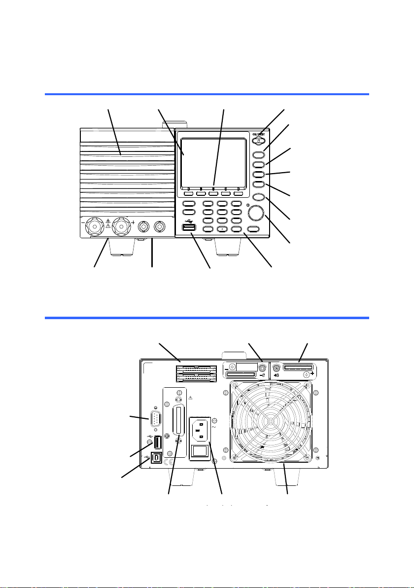
1-1.Front Panel Overview
I MON OUT TRIG OUT
1.5 - 150V
175W
0 - 35A
P0
P1
P4
P7
CAL.
P2
P5
P8
Lock
P3
P6
P9
Utility
Local
File
0
1
4
7
2
5
8
3
6
9
EnterClear
Shift
Preset
Load On/
Off
Main
Help
FUNC
Short
Air inlet LCD Display Power key
FUNC/ File
Help/ Utility
Short
Load On/ Off
USB Port, Preset
and Shift keys
Number pad, Clear/
Lock and Enter keys
Main/ Local
Scroll wheel
Function keys
Input
terminals
I MON OUT,
TRIG OUT
1-2.Rear Panel Overview
47 - 63 Hz
90 VA MAX.
AC
100 - 120 VAC
200 - 240 VAC
FRAME CONT
J 1
J 2
SER. NO. LB
RS232C
GPIB
WARNING
TO AVOID ELECTRIC SHOCK THE POWER CORD
DO NOT REMOVE COVERS.
NO OPERATOR SERVICEABLE COMPONENTS INSIDE.
PROTECTIVE GROUNDING CONDUCTOR MUST BE
REFER SERVICING TO QUALIFIED PERSONNEL.
CONNECTED TO GROUND.
Remote
sense inputs
Frame control
ports, J1, J2
RS-232C
port
USB
port
USB device
port Exhaust
fan
GP-IB Power socket
and switch
Rear panel
inputs
2
2.INTERFACE Configure
2-1.Configuring the USB Interface
USB
PC side connector
Type A, host
LSG side
connector
Rear panel Type B, device port
Speed
2.0 (full speed)
USB Class
USB CDC
Note
Before USB can be used for remote control, it is
necessary to install the USB device driver, located
on the accompanying User Manual CD.
Operation
1. Connect the USB cable to the rear panel USB B
port.
2. Press
Shift
+
Utility
Help
> Interfrace[F3] and
set the Interface setting to USB.
Please refer to the instruction manual for more
information.
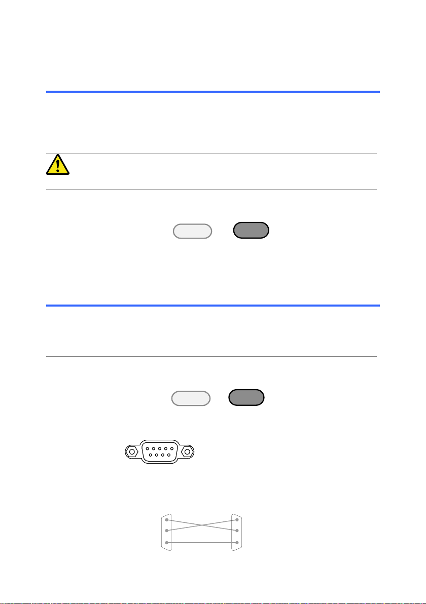
2-2.Configuring the RS-232C Interface
RS-232C
Connector
DB-9, Male
Baud Rate
2400, 4800, 9600, 19200, 38400
Stop Bit
1, 2
Parity
None, Odd, Even
Operation
1. Connect an RS-232C cable from the PC to the rear
panel RS-232C port.
2. Press
Shift
+
Utility
Help
> Interface[F3] and set
the Interface setting to RS232.
3. Set the Baud Rate, Stop Bit and Parity settings.
Pin Assignment
1 2 3 4 5
6 7 8 9
2: RxD (Receive data)
3: TxD (Transmit data)
5: GND
4,6,7,8,9: No connection
PC Connection
Use a null modem connection as shown in the diagram
below.
LSG PC
RxDPin2 RxD Pin2
GNDPin5 GND Pin5
TxD Pin3
TxDPin3

3
2-3.Configuring the GP-IB Interface
To use GP-IB, the optional GP-IB port must be installed.
Operation
Ensure the LSG Series is off before proceeding.
1. Connect a GP-IB cable from a GP-IB controller to
the GP-IB port on the LSG Series.
2. Turn the LSG Series on.
3. Press
Shift
+
Utility
Help
> Interface[F3] and set the
Interface setting to GP-IB.
4. Set the GP-IB address.
GP-IB address
0~30
GP-IB
constraints
Maximum 15 devices altogether, 20m
cable length, 2m between each device
Unique address assigned to each
device
At least 2/3 of the devices turned On
No loop or parallel connection
Pin
Assignment
112
1324
Pin
Signal
Pin
Signal
1~4
Data I/O 1~4
13~16
Data I/O 5~8
5
EOI
17
REN
6
DAV
18
Ground (DAV)
7
NRFD
19
Ground (NRFD)
8
NDAC
20
Ground (NDAC)
9
IFC
21
Ground (IFC)
10
SRQ
22
Ground (SRQ)
11
ATN
23
Ground (ATN)
12
SHIELD Ground
24
Single GND

4
2-4.RS-232C/USB Remote Control Function Check
Functionality
check
Invoke a terminal application such as Realterm or Putty.
For RS-232C, set the COM port, baud rate, stop bit, data
bit and parity accordingly.
To check the COM settings in Windows, see the Device
Manager from ControlPanel.
Note
If you are not familiar with using a terminal application to
send/receive remote commands from the serial port or via
a USB connection.
Run this query command via the terminal after the
instrument has been configured for RS-232/USB remote
control.
*idn?
This should return the Manufacturer, Model number, Serial
number, and Firmware version in the following format.
TEXIO,LSG SERIES, XXXXXXXXXXXX, V.X.X.X.X
Manufacturer: TEXIO
Model number : LSG SERIES
Serial number : XXXXXXXXXXXX
Firmware version : V.X.X.X
Note
For further details, please see the programming manual,
available on the TEXIO TECHNOLOGY web site
www.texio.co.jp
2-5.Using Realterm to Establish a Remote Connection
Background
Realterm is a terminal program that can be used to
communicate with a device attached to the serial port of a
PC or via an emulated serial port via USB.
The following instructions apply to version 1.99.0.27. Even
though Realterm is used as an example to establish a
remote connection, any terminal program can be used
that has similar functionality.
Note
Realterm can be downloaded on Sourceforge.net free of
charge.
For more information please see
http://realterm.sourceforge.net/
Operation
1. Download Realterm and install according to the
instructions on the Realterm website.
2. Connect the LSG Series via USB or via RS-232C
3. If using RS-232C, make note of the configured baud rate,
stop bits and parity.
4. Go to the Windows device manager and find the COM
port number for the connection.
Double click the Ports icon to reveal the connected serial
port devices and the COM port for the each connected
device.

5
The baud rate, stop bit and parity settings can be viewed
by right-clicking connected device and selecting the
Properties option.
5. Start Realterm on the PC as an administrator.
Click:
Start menu>All Programs>RealTerm>realterm
Tip: to run as an administrator, you can right click the
Realterm icon in the Windows Start menu and select the
Run as Administrator option.
6. After Realterm has started, click on the Port tab.
Enter the Baud, Parity, Data bits, Stop bits and Port
number configuration for the connection.
The Hardware Flow Control, Software Flow Control
options can be left at the default settings.
Press Open to connect to the LSG Series.
7. Click on the Send tab.
In the EOL configuration, check on the +CR and +LF
check boxes.
Enter the query:
*idn?
Click on Send ASCII.
6
8. The terminal display will return the following:
TEXIO, LSG-XXXX,EXXXXXXX,VX.XX.XXX
(manufacturer, model, serial number, version)
9. If Realterm fails to connect to the LSG Series, please
check all the cables and settings and try again.
2-6.GP-IB Function Check
Functionality
check
Please use the National Instruments Measurement &
Automation Controller software to confirm GP-IB
functionality.
See the National Instrument website, http://www.ni.com
for details.
Note
For further details, please see the programming manual,
available on the TEXIO TECHNOLOGY web site
www.texio.co.jp
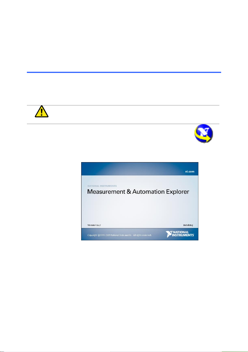
Operation
1. Start the NI Measurement and Automation
Explorer (MAX) program. Using Windows,
press:
Start>All Programs>National Instruments>Measurement
& Automation
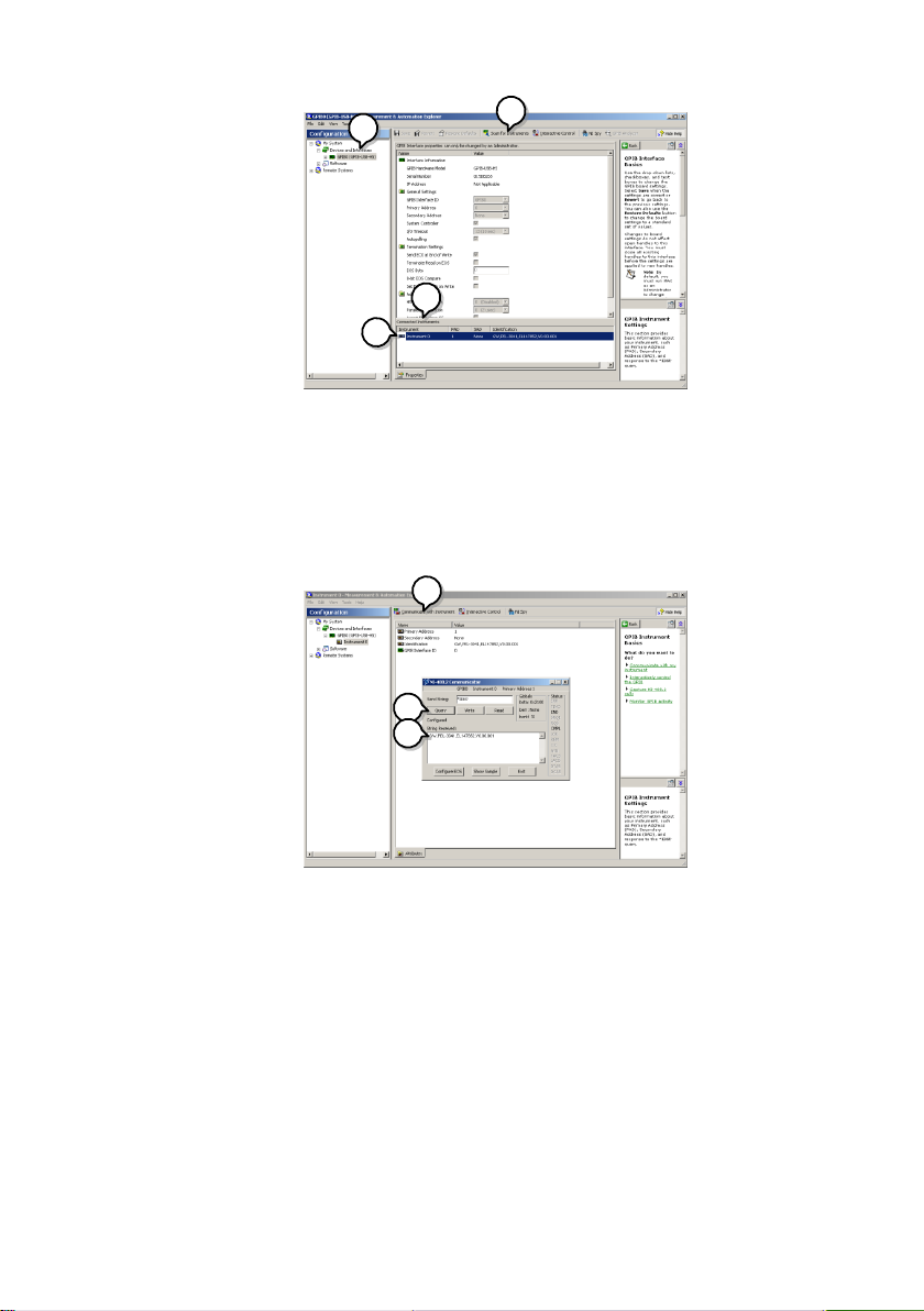
2. From the Configuration panel access;
My System>Devices and Interfaces>GPIB0
3. Press the Scan for Instruments button.
4. In the Connected Instruments panel the LSG Series
should be detected as Instrument 0 with the address the
same as that configured on the LSG Series.
5. Double click the Instrument 0 icon.
7
23
4
5
6. Click on Communicate with Instrument.
7. In the NI-488.2 Communicator window, ensure *IND? is
written in the Send String: text box.
Click on the Query button to send the *IDN? query to the
instrument.
8. The String Received text box will display the query return:
TEXIO, LSG-XXXX,EXXXXXXX,VX.XX.XXX
(manufacturer, model, serial number, version)
6
7
8
9. The function check is complete.

8
3.COMMAND OVERVIEW
The command syntax section shows you the basic syntax rules you have
to apply when using commands.
3-1.Command Syntax
Compatible
Standard
IEEE488.2
Partial compatibility
SCPI, 1999
Partial compatibility
Command
Structure
SCPI (Standard Commands for Programmable
Instruments) commands follow a tree-like structure,
organized into nodes. Each level of the command
tree is a node. Each keyword in a SCPI command
represents each node in the command tree. Each
keyword (node) of a SCPI command is separated by
a colon (:).
For example, the diagram below shows an SCPI
sub-structure and a command example.
:RESPonse:CRANGe :VRANGe
[:MODE]:CRANGe
:MODE
Command types
There are a number of different instrument
commands and queries. A command sends
instructions or data to the unit and a query receives
data or status information from the unit.
Command types
Simple
A single command with/without a
parameter
Example
:CONFigure:RESPonse MAX
Query
A query is a simple or compound
command followed by a question
mark (?). A parameter (data) is
returned.
Example
:CONFigure:RESPonse?
Compound
Two or more commands on the
same command line. Compound
commands are separated with
either a semi-colon (;) or a
semi-colon and a colon (;:).
A semi-colon is used to join two
related commands, with the caveat

9
that the last command must begin
at the last node of the first
command.
Asemi-colon and colon are used to
combine two commands from
different nodes.
Example
CONFigure:VON
MAX;:CONFigure:VDELay MIN
Command
Forms
Commands and queries have two different forms,
long and short. The command syntax is written with
the short form of the command in capitals and the
remainder (long form) in lower case.
The commands can be written in capitals or
lower-case, just so long as the short or long forms
are complete. An incomplete command will not be
recognized.
Below are examples of correctly written commands.
Long form
Short form:
:CURRENT:LEVEL?
:current:level?
:CURR:LEV?
:curr:lev?
Square Brackets
Commands that contain square brackets indicate
that the contents are optional. The function of the
command is the same with or without the square
bracketed items, as shown below
For example for the query:
“[:CONFigure]:GNG [:PASS]?”
Both “:CONFigure:GNG:PASS?” and “:GNG?” are
both valid forms.
Command
Format
1.00A
12 3 4
:CURRent:Set
1. Command header
2. Space
3. Parameter 1
4. Unit or suffix.
Common
Input
Parameters
Type
Description
Example
<Boolean>
boolean logic
0, 1
<NR1>
integers
0, 1, 2, 3
<NR2>
decimal
numbers
0.1, 3.14, 8.5
<NR3>
floating point
4.5e-1, 8.25e+1
<NRf>
any of NR1, 2, 3
1, 1.5, 4.5e-1

10
[MIN]
(Optional
parameter)
For commands, this will set the
setting to the lowest value. This
parameter can be used in place of
any numerical parameter where
indicated.
For queries, it will return the lowest
possible value allowed for the
particular setting.
[MAX]
(Optional
parameter)
For commands, this will set the
setting to the highest value. This
parameter can be used in place of
any numerical parameter where
indicated.
For queries, it will return the highest
possible value allowed for the
particular setting.
Unit Suffixes
(Optional
parameters)
Unit suffixes can be optionally used
with most NRf type input parameters.
[A]
Amps
1.00A
[%]
Percentage
10%
[V]
Volts
5.00V
[W]
Watts
3.00W
[ms]
milliseconds
20ms
[mV]
Millivolts
150mV
[s]
Seconds
5s
[ohm]
Ohm
50ohm
[mS]
Reciprocal of 1k ohms
20mS
[MHO]
Reciprocal of one ohm
0.02MHO
[mA/uS]
Millamps/microsecond
100mA/uS
[Hz]
Hertz
6.0e+1Hz
Message
Terminator
LF
Line feed code (0x0A)

11
4.COMMAND DETAILS
4-1.Common Commands
4-1-1. *CLS
Set
Description
Clears all Event registers and queues.
Syntax
*CLS
Example
*CLS
Clears all Event registers and queues.
4-1-2. *ESE
Set
Query
Description
Queries or sets the Standard Event Status Enable
register. The Standard Event Status Enable register
determines which events can set the Event Summary
bit (ESB) in the Status Byte Register. Any bits that are
set to 1 enable the corresponding event. Each event is
represented by a bit in the Standard Event Status
Enable register.
Refer to the Standard Event Status register group for
more information on bit.
Syntax
*ESE <NRf>
Query Syntax
*ESE?
Parameter
<NR1>
Sets the Standard Event Status
Enable register.
Return
parameter
Return in "<NR1>" the set value of the Standard Event
Status Enable register.
Example
*ESE 8
Sets bit 3 of the ESE register.
Query example
*ESE?
>12
Bits 2 and 3 are set in the Standard Event Status
Enable register.
4-1-3. *ESR
Set
Query
Description
Reads the Standard Event Status register. This
command will also clear the Standard Event Status
register.
Refer to the Standard Event Status register group for
more information on bit.
12
Query Syntax
*ESR?
Return
parameter
Return in "<NR1>" the set value of the Standard Event
Status register.
Query example
*ESR?
>48
Bits 4 and 5 are set in the Standard Event register.
4-1-4. *IDN
Query
Description
Queries the manufacturer, model number, serial
number, and firmware version of the instrument.
Query Syntax
*IDN?
Return
parameter
<string>
<string>
<NR1>
<string>
Returns the manufacture name.
Returns the model name.
Returns the serial number.
Returns the version of firmware.
Query example
* IDN?
> TEXIO,LSG-175,12345678,V1.01.001
It is a response equipment manufacturer, model
number, serial number, and firmware version.
4-1-5. *OPC
Set
Query
Description
This command sets the OPC (Operation Command Bit)
bit (bit 0) of the Standard Event Status Register after the
instrument has completed all pending operations. The
query will return the status of the OPC bit.
Syntax
*OPC
Query Syntax
*OPC?
Return
parameter
1
Operation complete.
Example
*OPC
Query Example
*OPC?
>1
Indicates that all pending operations are complete.
4-1-6. *RCL
Set
Description
The Recall Instrument State command restores the
instrument settings from a previously saved memory
setting.
Syntax
*RCL <NR1>
Parameter
<NR1>
Memory number 1 to 256
Other manuals for LSG SERIES
1
This manual suits for next models
3
Table of contents


