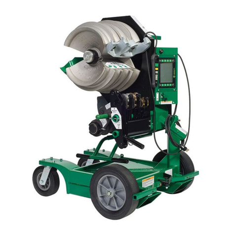
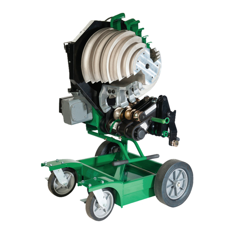
Textron GREENLEE 854 User manual

INSTRUCTION MANUAL
854
Quad Bender
Read and understand all of the instructions and
safety information in this manual before operating
or servicing this tool.
99922223 © 2007 Greenlee Textron Inc. IM 1301 REV 13 10/07
Beginning with Serial Number ABT0000

854 Quad Bender
Greenlee / A Textron Company 4455 Boeing Dr. • Rockford, IL 61109-2988 USA • 815-397-7070
2
KEEP THIS MANUAL
Table of Contents
Description .................................................................... 2
Safety ............................................................................ 2
Purpose ......................................................................... 2
Important Safety Information .....................................3–4
Grounding Instructions.................................................. 5
Identication.................................................................. 6
Specications................................................................ 6
Transportation and Setup.............................................. 7
Operation....................................................................8–9
Illustrated Bending Glossary ....................................... 10
Bending Instructions ..............................................11–12
Special Bending Information ..................................13–20
Maintenance...........................................................21–23
Troubleshooting......................................................24–25
Exploded Views, Parts Lists,
Schematics and Wiring Diagrams ..........................26–49
Description
The Greenlee 854 Quad Bender is an electric-powered
conduit and pipe bender, intended to make up to 90°
bends in 1/2" to 2" conduit and pipe. It is capable of
bending the following:
EMT
IMC
Rigid Aluminum
Rigid Steel
40 Mil PVC-Coated Rigid Steel (requires PVC Shoe
Group 01700, purchased separately)
Schedule 40 Pipe
Note: This equipment has been tested and found to
comply with the limits for a Class A digital device, pursuant
to Part 15 of the Federal Communications Commission
rules. These limits are designed to provide reasonable
protection against harmful interference when the equip-
ment is operated in a commercial environment. This
equipment generates, uses, and can radiate radio fre-
quency energy and, if not installed and used in accordance
with the instruction manual, may cause harmful interference
to radio communications. Operation of this equipment in a
residential area is likely to cause harmful interference, in
which case the user will be required to correct the interfer-
ence at his own expense.
Do not make any modifications to this device. Unauthorized
changes or modifications will void the user’s authority to
operate this device under United States federal law.
•
•
•
•
•
•
Safety
Safety is essential in the use and maintenance of
Greenlee tools and equipment. This instruction manual
and any markings on the tool provide information for
avoiding hazards and unsafe practices related to the
use of this tool. Observe all of the safety information
provided.
Purpose of this Manual
This manual is intended to familiarize personnel with
the safe operation and maintenance procedures for the
following tool:
854 (03106) Serial Number ABT0000
Keep this manual available to all personnel.
Replacement manuals are available upon request at
no charge at www.greenlee.com.
All specications are nominal and may change as design
improvements occur. Greenlee Textron Inc. shall not be liable for
damages resulting from misapplication or misuse of its products.
Loctite is a registered trademark of Loctite Corporation.

854 Quad Bender
Greenlee / A Textron Company 4455 Boeing Dr. • Rockford, IL 61109-2988 USA • 815-397-7070
3
IMPORTANT SAFETY INFORMATION
SAFETY
ALERT
SYMBOL
This symbol is used to call your attention to hazards
or unsafe practices which could result in an injury or
property damage. The signal word, dened below,
indicates the severity of the hazard. The message
after the signal word provides information for pre-
venting or avoiding the hazard.
Immediate hazards which, if not avoided, WILL result
in severe injury or death.
Hazards which, if not avoided, COULD result in
severe injury or death.
Hazards or unsafe practices which, if not avoided,
MAY result in injury or property damage.
Read and understand all of the
instructions and safety information
in this manual before operating or
servicing this tool.
Failure to observe this warning will
result in severe injury or death.
Do not use this tool in a hazard-
ous environment. Hazards include
ammable liquids, gases, or other
materials. Using this tool in a hazard-
ous environment can result in a re
or explosion.
Failure to observe this warning will
result in severe injury or death.
Electric shock hazard:
Connect the power cord to a
120 volt, 20 amp receptacle on a
ground fault protected circuit only.
See Grounding Instructions.
Do not modify the power cord or
plug.
Inspect the power cord before
use. Repair or replace the cord if
damaged.
Disconnect the unit from power
before servicing.
Failure to observe these warnings
could result in severe injury or death.
•
•
•
•
Do not expose to rain.
Do not use in wet or damp
locations.
Do not immerse the pendant
switch in water or any other liquid.
Failure to observe these warnings
could result in severe injury or death.
•
•
•
Wear eye protection when operating
or servicing this tool.
Failure to wear eye protection could
result in serious eye injury from ying
debris.
Do not remove guards.
Failure to observe this warning could
result in severe injury or death.

854 Quad Bender
Greenlee / A Textron Company 4455 Boeing Dr. • Rockford, IL 61109-2988 USA • 815-397-7070
4
Extension cords:
Use only three-wire, 12-gauge
extension cords that have three-
prong grounding-type plugs and
three-hole receptacles that accept
the tool’s plug.
Do not use extension cords that
are longer than 30 m (100').
Repair or replace damaged
extension cords.
Failure to observe these warnings
could result in severe injury or death.
•
•
•
Pinch points:
Keep hands away from bending
shoe, rollers and conduit when
bender is in use.
Failure to observe this warning could
result in severe injury or death.
Unplug the bender before changing accessories.
Accidental start-up could result in serious injury.
Do not operate the bender while wearing loose
clothing. Loose clothing can get caught in moving
parts.
Failure to observe this warning could result in severe
injury or death.
IMPORTANT SAFETY INFORMATION
Inspect the bender before each use. Replace worn,
damaged, or missing parts with Greenlee replace-
ment parts. A damaged or improperly assembled
component could break and strike nearby
personnel.
Do not overbend the conduit or pipe. Overbending
could cause a hook to collide with the conduit or
pipe, resulting in damage to the bender.
Conduit moves rapidly as it is bent. Before starting
a bend, remove any obstructions from the path of
the conduit.
Some of the components and accessories are
heavy and may require two people to lift and
assemble.
Use this tool for the manufacturer’s intended
purpose only.
Failure to observe these precautions may result in
injury or property damage.
•
•
•
•
•
Note: Keep all decals clean and legible, and replace
when necessary.

854 Quad Bender
Greenlee / A Textron Company 4455 Boeing Dr. • Rockford, IL 61109-2988 USA • 815-397-7070
5
Grounding Instructions
Electric shock hazard:
Do not modify the plug provided
with the tool.
Connect this tool to a grounded
receptacle on a 20 amp GFCI-
protected circuit.
Failure to observe these warnings
could result in severe injury or death.
•
•
This tool must be grounded. In the event of a malfunc-
tion or breakdown, an electrical ground provides a path
of least resistance for the electric current. This path of
least resistance is intended to reduce the risk of electric
shock.
This tool’s electric cord has a grounding conductor and
a grounding plug as shown. Do not modify the plug.
Connect the plug to a corresponding GFCI protected
receptacle that is properly installed and grounded
in accordance with all national and local codes and
ordinances.
Do not use an adapter.
20 Amp/120 Volt
Plug and Receptacle
ReceptaclePlug

854 Quad Bender
Greenlee / A Textron Company 4455 Boeing Dr. • Rockford, IL 61109-2988 USA • 815-397-7070
6
Identification
Specifications
Height .....................................................................................................1200 mm (47")
Width .....................................................................................................724 mm (28.5")
Depth.....................................................................................................902 mm (35.5")
Mass/Weight (bender without shoes or roller supports).........................231 kg (510 lb)
Power Supply ............................................... 120 VAC, 20 amp GFCI-protected circuit
Operating Conditions
Temperature .............................................................. 0 °C to 49 °C (32 °F to 120 °F)
Relative Humidity ........................................................................................0 to 98%
Capacity ........................................................ 1/2" to 2" conduit and schedule 40 pipe
854 Conduit Bender
1. Bender Power Head
2. 1/2" to 1-1/4" Bending Shoe
3. On/Off Switch and Circuit Breaker
4. Bender Head Pivot Lock Knob
5. Lifting Eyes
6. Lockable Storage Area
7. Support Frame
8. Leveling Jack Screws
9. Support Roller Squeeze Adjustment
10. Support Roller Engagement Handle
11. 1-1/2" to 2" Roller Support System
12. 1-1/2" to 2" Bending Shoe
13. Shoe Retaining Lock Ring
14. Open Storage Area
15. Transport Handle
13
12
11
10
9
2
3
1
5
4
7
6
8 8
2
14
15

854 Quad Bender
Greenlee / A Textron Company 4455 Boeing Dr. • Rockford, IL 61109-2988 USA • 815-397-7070
7
Pivoting the Bender Head
The bender head has two bending positions — vertical
and horizontal. To change the bender head position:
1. Pull out the bender head pivot lock knob. It may be
necessary to twist the knob clockwise until the pin
clears the frame.
2. Pivot the bending head to the desired bending
position.
3. Push the bender head pivot lock knob back into
position so that the pin is fully engaged in the hole.
4. Twist the pivot lock knob counterclockwise until you
feel some resistance. Do not tighten it.
Lowering the Jack Screws
The bender is equipped with four jack screws. To park
the bender at the jobsite, use the 5/16" T-handle Allen
wrench, which is shipped in the lockable storage area,
to lower two of the jack screws. If desired, lower all four
jack screws to level the bender.
Transportation and Setup
Hoisting the Bender
To hoist the bender, use either slings (nylon or polyester)
or chains with hooks. Each side of the sling or chain
must be at least 915 mm (36") long to prevent contact
with the bender. All lifting components must be rated for
231 kg (510 lb).
1. Pivot the bending head to the horizontal position
with the 1-1/2" to 2" shoe upward (see Pivoting the
Bender Head in this section of the manual).
2. Rotate the lifting eyes so they are accessible.
3. Loop the slings through, or attach the hooks to, the
lifting eyes.
4. Hoist the bender.

854 Quad Bender
Greenlee / A Textron Company 4455 Boeing Dr. • Rockford, IL 61109-2988 USA • 815-397-7070
8
Operation
Do not use this tool in a hazard-
ous environment. Hazards include
ammable liquids, gases, or other
materials. Using this tool in a hazard-
ous environment can result in a re
or explosion.
Failure to observe this warning will
result in severe injury or death.
Electric shock hazard:
Connect the power cord to a
120 volt, 20 amp receptacle on a
ground fault protected circuit only.
See Grounding Instructions.
Do not modify the power cord or
plug.
Inspect the power cord before
use. Repair or replace the cord if
damaged.
Disconnect the unit from power
before servicing.
Failure to observe these warnings
could result in severe injury or death.
•
•
•
•
Wear eye protection when operating
or servicing this tool.
Failure to wear eye protection could
result in serious eye injury from ying
debris.
Pinch points:
Keep hands away from bending
shoe, rollers and conduit when
bender is in use.
Failure to observe this warning could
result in severe injury or death.
Unplug the bender before changing accessories.
Accidental start-up could result in serious injury.
Do not operate the bender while wearing loose cloth-
ing. Loose clothing can get caught in moving parts.
Failure to observe this warning could result in severe
injury or death.
1. Mark the conduit.
The decals on the bender and the Bending
Instructions section of this manual provide basic
instructions for marking and bending the conduit.
They are based on measurements with common
fractions for accurate results.
For a higher level of precision, see the Special
Bending Information section of this manual. This
section is based on measurements carried out to
two decimal places.
2. Turn the power switch/circuit breaker to ON.
3. Use the shoe selection switch on the side of the
bender to select the proper shoe (1/2" to 1-14" shoe
or 1-1/2" to 2" shoe). Press BEND or UNLOAD until
the pointer of the selected shoe is 5° to 10° before
the 0° starting point.
4. Insert the conduit into the proper shoe groove and
hook (green hooks indicate IMC, rigid, and sched-
ule 40 pipe; silver hooks indicate EMT). Load the
conduit so that the bending mark is aligned with the
front edge of the shoe hook.
If bending 1/2" to 1/14" conduit, use the roller
support unit as explained under Operation.
If bending 1-1/2" to 2" EMT, IMC or rigid alu-
minum, use the roller support unit and set the
squeeze as explained under Operation.
If bending 1-1/2" to 2" rigid steel conduit or
schedule 40 pipe, ensure that the roller support
unit is in the lowered position.
5. See the instruction decal or the Scale Reading Table
for the appropriate bend angle.
6. Bend the conduit:
a. Press and hold BEND.
b. Release the BEND switch as you approach the
desired angle of bend.
c. Press BEND momentarily until the bend is
complete.
7. Unload the bender.
a.
Press UNLOAD. The shoe will rotate back and drop
the 1-1/2" to 2" roller support unit, if it was used.
b. Twist the conduit to release it from the hook.
Remove the conduit.
c. Press and hold UNLOAD until the shoe has
rotated back to 0°.
•
•
•
•
•
854 Quad Bender
Greenlee / A Textron Company 4455 Boeing Dr. • Rockford, IL 61109-2988 USA • 815-397-7070
9
Operation (cont’d)
USING ROLLER SUPPORT UNITS
Use the roller support units to squeeze the conduit as it
is bent.
Using the 1/2" to 1-1/4" Roller Support Unit
Pivot this roller support upward and into place when
bending all types of 1/2" to 1-1/4" conduit. Pivot the
roller support down for easier loading and unloading.
Using the 1-1/2" to 2" Roller Support Unit
Engage this roller support when bending 1-1/2" to 2"
EMT, IMC, and rigid aluminum conduit:
1. Load the conduit.
2. While momentarily pressing BEND, move the roller
engagement handle up and to the left. The rollers
will move up and squeeze the conduit against the
shoe. Apply enough force so that the roller support
unit contacts the stops before the conduit starts to
bend.
Note: If it is difficult to engage the rollers completely,
the squeeze is probably set too high. See Adjusting the
Squeeze in this section of the manual.
ADJUSTING THE SQUEEZE
When bending 1-1/2" to 2" EMT, IMC, and rigid alumi-
num conduit, the roller support must be engaged so that
the roller supports the conduit; the pressure against the
conduit is the “squeeze”. Setting the squeeze adjust-
ment arm to the vertical position (middle hole) provides
the necessary amount of squeeze for most 1-1/2" to 2"
EMT and IMC conduit.
Due to variations in conduit, the standard adjustment
may provide too much or too little squeeze.
If the conduit is difcult to load or develops excessive
side marking when bent, the squeeze is set too high.
If the conduit becomes excessively oval or wrinkled,
the squeeze is set too low.
To change the amount of squeeze:
1. Loosen the adjustment arm screw.
2. Rotate the adjustment arm one position counter-
clockwise to INCREASE the squeeze or one posi-
tion clockwise to DECREASE the squeeze.
Note: Decrease the squeeze by three settings when
bending rigid aluminum conduit.
3. Align the adjustment arm with one of the holes and
tighten the screw.
Changing the squeeze may affect the bending accuracy.
If the pointers are inaccurate after changing the
squeeze, see Pointer Accuracy under Maintenance.
•
•

854 Quad Bender
Greenlee / A Textron Company 4455 Boeing Dr. • Rockford, IL 61109-2988 USA • 815-397-7070
10
back-to-back bend — any U-shaped bend formed by two
parallel 90° bends with a straight section of conduit or pipe
between the bends.
center-to-center distance — the distance between the suc-
cessive bends that make up an offset or a three-bend saddle.
developed length — the actual length of pipe that will be bent;
see distance “d” in the illustration at left.
gain — the difference between the straight-line distance
(a + a) and the shorter radial distance, (d) where:
θ= angle of bend
r = the centerline bending radius of the bending shoe
kick — single bend of less than 90°
leg length — the distance from the end of a straight section
of conduit or pipe to the bend; measured from the end to the
outside edge of the conduit or pipe.
offset bend — two opposite bends with the same degree of
bend; used to avoid an obstruction.
offset height — the distance between the two legs of
an offset bend, measured perpendicular to the two legs; also
called amount of offset and depth of offset.
rise — the distance from the end of a straight section of
conduit or pipe to the bend; measured from the end to the
center line of the conduit or pipe. Also called stub or
stub-up.
saddle — a three-bend or four-bend combination; used
to avoid an obstruction.
shrink — the amount of conduit “lost” when laying out an
offset bend working toward an obstruction; see the explanation
under Offset Bending in this manual.
springback — the amount, measured in degrees, that a
conduit or pipe tends to straighten after being bent.
Illustrated Bending Glossary
a
a
d
r
Offset Height

854 Quad Bender
Greenlee / A Textron Company 4455 Boeing Dr. • Rockford, IL 61109-2988 USA • 815-397-7070
11
Bending Instructions
Single Bends (Stubs and Kicks)
1. Measure the length of the required stub.
2. See the Minimum Stub on the Deduct Table. The
required stub must be equal to or longer than the
Minimum Stub.
3. Measure and mark the stub length on the conduit.
This is the Stub Length Mark. Subtract the Deduct
from this mark and make a new mark. This is
Bending Mark 1.
4. Align Bending Mark 1 with the front edge of the
hook and bend the conduit.
Note: When the operator presses UNLOAD, the conduit
may spring back a few degrees. Compensate by over-
bending as shown in the Scale Reading Table.
STUB LENGTH
STUB
LENGTH
MARK
BENDING
MARK 1 DEDUCT
STUB
LENGTH
MARK
BENDING
MARK 1
STUB LENGTH
Deduct Table
Conduit
Size
EMT IMC/Rigid
Deduct Miminum
Stub
Deduct Minimum
Stub
1/2" 7-1/2 9-1/2 7-1/2 9-1/2
3/4" 9 11 9 11
1" 11 13 11 13
1-1/4" 13-5/8 15-5/8 13-5/8 15-5/8
1-1/2" 14-7/8 16-7/8 14-7/8 16-7/8
2" 16-3/8 18-3/8 16-1/8 18-1/8
Conduit Size Conduit Type Start (0°) 15° 22-1/2° 30° 45° 60° 90°
EMT 1 16-1/2 24 31-1/2 46-1/2 61-1/2 91-1/2
IMC 2-1/2 17-1/2 25-1/2 33 48 63-1/2 93-1/2
1/2" RIG 1 16-1/2 24 31-1/2 46-1/2 61-1/2 91-1/2
AL 1 16 23-1/2 31 46-1/2 61-1/2 91-1/2
PVC 1-1/2 16-1/2 24 31-1/2 46-1/2 61-1/2 91-1/2
EMT 1 16 24 31-1/2 46-1/2 62 92-1/2
IMC 1 16-1/2 24 31-1/2 47 62 92-1/2
3/4" RIG 1/2 15-1/2 23 30-1/2 45-1/2 60-1/2 90-1/2
AL 1/2 15-1/2 23-1/2 31 46 61-1/2 92
PVC 0 15 22-1/2 30 45 60 90
EMT 0 15 22-1/2 30 45-1/2 60-1/2 90-1/2
IMC 2 17 24-1/2 32 47 62 92-1/2
1" RIG 1 16 23-1/2 31 46 61 91
AL 1/2 15-1/2 23-1/2 31 46 61-1/2 91-1/2
PVC 1/2 15-1/2 23 30-1/2 45-1/2 60-1/2 90-1/2
EMT 1 16 23-1/2 31-1/2 46-1/2 61-1/2 92
IMC 2 17-1/2 25 32-1/2 47-1/2 62-1/2 92-1/2
1-1/4" RIG 1 16 23-1/2 31 46 60-1/2 90-1/2
AL 1-1/2 16-1/2 24 31-1/2 46-1/2 61-1/2 91-1/2
PVC 1/2 15-1/2 23 30-1/2 45-1/2 60-1/2 90-1/2
EMT 1 16 24 31-1/2 46-1/2 61-1/2 92
IMC 2 17 25 32-1/2 47-1/2 63 93-1/2
1-1/2" RIG 0 15 22-1/2 30 45 60 90-1/2
AL 1 16 23-1/2 31 46 61-1/2 91-1/2
PVC 1/2 16 23-1/2 31 46 61 91
EMT 1/2 15 22-1/2 30 45 59-1/2 89
IMC 3-1/2 18-1/2 26 33-1/2 48-1/2 63-1/2 94
2" RIG 1 16 23-1/2 31 45-1/2 60-1/2 90-1/2
AL 2 17 24-1/2 32 47 61-1/2 91-1/2
PVC 2 17 24-1/2 31-1/2 46-1/2 61-1/2 91-1/2
Scale Reading Table

854 Quad Bender
Greenlee / A Textron Company 4455 Boeing Dr. • Rockford, IL 61109-2988 USA • 815-397-7070
12
Bending Instructions (cont’d)
Offsets
1. Measure the height and length of the
obstruction. Select the angle to be used.
2. Refer to the X Table for the X dimension,
and refer to the Offset Table for the center-
to-center distance.
Note: If the center-to-center distance is not
shown, calculate it by using the multipliers
shown in the Offset Table.
3. Mark the conduit as shown.
4. Insert the conduit into the bender. Align
Bending Mark 1 with the front edge of the
hook and bend the conduit.
5. Without removing the conduit from the
bender, align Bending Mark 2 with the front
edge of the hook and rotate the conduit
180°. Make the second bend.
C
E
N
T
E
R
T
O
C
E
N
T
E
R
BENDING
MARK 1
BENDING
MARK 1
BENDING
MARK 2
BENDING
MARK 2
START OF BEND
START OF BEND
CENTER TO CENTER
X
X
Conduit Size X
1/2" 2-1/2
3/4" 3-1/16
1" 3-1/16
1-1/4" 4
1-1/2" 4-3/4
2" 4-3/4
Offset
Finished Angle
15° 30° 45°
Maximum
Conduit
Size
Center-
to-center
Maximum
Conduit
Size
Center-
to-center
Maximum
Conduit
Size
Center-
to-center
2 3/4 7-3/4
4 1-1/2 15-7/16 3/4 7-15/16
6 2 23-3/16 1 11-15/16 1/2 8-5/16
8 2 30-7/8 1-1/2 15-15/16 1 11-1/16
10 2 38-5/8 2 19-15/16 1-1/4 13-13/16
12 2 46-3/8 2 23-15/16 1-1/2 16-5/8
14 2 54-1/16 2 27-15/16 2 19-7/16
16 2 61-13/16 2 31-15/16 2 22-1/4
18 2 69-9/16 2 35-15/16 2 25-1/16
20 2 77-1/4 2 39-15/16 2 27-15/16
22 2 85 2 43-15/16 2 30-3/4
X Table Offset Table

854 Quad Bender
Greenlee / A Textron Company 4455 Boeing Dr. • Rockford, IL 61109-2988 USA • 815-397-7070
13
Special Bending Information
The Special Bending Information section and the
Special Bending Information Chart are used together for
making very precise bends.
The Special Bending Information Chart is divided into
sections by the size and type of conduit. Each section
contains dimensions (such as Y, L1, L2, and Z) that
correspond to the illustrations. The top row of the
Special Bending Information Chart shows some of the
typical heights (2", 4", 6", etc), which correspond to the
heights in the illustrations.
SINGLE BENDS (Stubs and Kicks)
1. Select the size and type of conduit. Determine the
height of the stub or kick and the angle to be used.
2. Find the corresponding section of the Special
Bending Information Chart.
3. In the row at the top of the page, nd the height of
the stub. Under the height, nd the corresponding
Y dimension.
4. Mark the conduit as shown. Bend the conduit.
Y
HEIGHT
MARK
ANGLE
OFFSETS
An offset is used to route the conduit around an
obstruction. To make an offset, two equal bends are
required. The distance between the two bends is the
center-to-center distance.
When working past an obstruction, it is necessary to
determine the location of the rst bend. The center-to-
center distance is then used to measure and mark the
distance to the second bend.
When working toward an obstruction, it is necessary to
determine the location of the second bend. The center-
to-center distance is then used to measure and mark
the distance to the rst bend.
Offsets — Working Past an Obstruction
1. Select the size and type of conduit. Measure the
height of the obstruction and the distance labeled
LENGTH. Determine the angle to be used.
2. Find the X dimension in the X Table under Bending
Instructions. Subtract X from the LENGTH and mark
the conduit, as shown.
3. Find the corresponding section of the Special
Bending Information Chart.
4. In the row at the top of the page, nd the height of
the obstruction. Under the height, nd the corre-
sponding L1 dimension.
5. Mark the conduit as shown. Bend the conduit.
Note: After the first bend, do not remove the
conduit from the bender. Advance the conduit until
the second bending mark is aligned with the front
edge of the hook, rotate the conduit 180°, and make
the second bend.
START OF
FIRST BEND
LENGTH
ANGLE
HEIGHT
BENDING
MARK 1
BENDING
MARK 2
LENGTH – X L1
Offsets — Working Toward an Obstruction
1. Select the size and type of conduit. Measure the
height of the obstruction and the distance labeled
LENGTH TO END OF SECOND BEND. Determine
the angle to be used.
2. Find the corresponding section of the Special
Bending Information Chart.
3. In the row at the top of the page, nd the height of
the obstruction. Under the height, nd the corre-
sponding L1 and Z dimensions.
4. Mark the conduit as shown. Bend the conduit.
Note: After the first bend, do not remove the
conduit from the bender. Advance the conduit until
the second bending mark is aligned with the front
edge of the hook, rotate the conduit 180°, and make
the second bend.
BENDING
MARK 1
BENDING
MARK 2
HEIGHT
LENGTH TO END OF SECOND BEND
ANGLE
LENGTH – Z L1

854 Quad Bender
Greenlee / A Textron Company 4455 Boeing Dr. • Rockford, IL 61109-2988 USA • 815-397-7070
14
Special Bending Information (cont’d)
THREE-BEND SADDLE
A three-bend saddle is used to route the conduit around
an obstruction. To make a three-bend saddle, three
bends are required; the rst and third bends are an
equal number of degrees; the second bend is twice that
number of degrees.
1. Select the size and type of conduit. Measure the
height of the obstruction and the distance labeled
LENGTH TO CENTER. Determine the angle to be
used.
Note: The “angle to be used” is the first and third
angle of the saddle (not the second), as illustrated.
Refer to this angle when looking up the correspond-
ing information in the Special Bending Information
Chart.
2. Find the corresponding section of the Special
Bending Information Chart.
3. In the row at the top of the page, nd the height of
the obstruction. Under the height, nd the corre-
sponding L1, L2 and Z dimensions.
4. Mark the conduit as shown. Bend the conduit.
Note: After the first bend, do not remove the
conduit from the bender. Advance the conduit until
the second bending mark is aligned with the front
edge of the hook, rotate the conduit 180°, and make
the second bend. Then advance the conduit to the
third bending mark, rotate the conduit 180° again,
and make the third bend.
BENDING
MARK 1
BENDING
MARK 3
BENDING
MARK 2
LENGTH – Z L1 L2
LENGTH TO CENTER
ANGLE
HEIGHT
FOUR-BEND SADDLE
1. Select the size and type of conduit. Measure the
distances labeled LENGTH, STRAIGHT SECTION,
and HEIGHT. Determine the angle to be used.
2. Find the corresponding section of the Special
Bending Information Chart.
3. In the row at the top of the page, nd the height of
the obstruction. Under the height, nd the corre-
sponding L1, L2 and Z dimensions.
4. Mark the conduit as shown. Bend the conduit.
BENDING
MARK 1
BENDING
MARK 3
BENDING
MARK 4
BENDING
MARK 2
LENGTH – Z L1 L1
ANGLE
HEIGHT
LENGTH STRAIGHT
SECTION
L2 + STRAIGHT SECTION
U-BENDS
1. Select the size and type of conduit. Measure and
mark the distances labeled HEIGHT and LENGTH.
2. Find the corresponding section of the Special
Bending Information Chart.
3. In the row at the top of the page, nd the height
of the illustration. Under the height, nd the corre-
sponding L1 and Y dimensions.
4. Mark the conduit as shown. Bend the conduit.
BENDING
MARK 1
BENDING
MARK 2
Y L1
HEIGHT
LENGTH

854 Quad Bender
Greenlee / A Textron Company 4455 Boeing Dr. • Rockford, IL 61109-2988 USA • 815-397-7070
15
Special Bending Information Chart
DIM ANGLE 2" 4" 6" 8" 10" 12" 15" 18" 24" 36"
1/2" EMT
Y 15 3.28 11.01 18.73 26.45 34.18 41.91 53.50 65.09 88.27 134.64
L1 15 7.72 15.45 23.18 30.90 38.63 46.36 57.95 69.54 92.72 139.09
L2 15 8.88 16.61 24.34 32.07 39.79 47.52 59.11 70.70 93.88 140.25
Z 15 11.13 18.60 26.06 33.53 40.99 48.45 59.65 70.85 93.24 138.02
MINIMUM H = 0.95
Y 22.5 .92 6.14 11.37 16.59 21.82 27.05 34.89 42.73 58.40 89.76
L1 22.5 5.20 10.43 15.66 20.88 26.11 31.33 39.17 47.01 62.69 94.05
L2 22.5 6.95 12.17 17.40 22.63 27.85 33.08 40.92 48.76 64.44 95.79
Z 22.5 9.09 13.92 18.75 23.58 28.41 33.24 40.48 47.72 62.21 91.18
MINIMUM H = 1.63
Y 30 3.60 7.60 11.60 15.60 19.60 25.60 31.60 43.60 67.60
L1 30 7.95 11.95 15.95 19.95 23.95 29.95 35.95 47.95 71.95
L2 30 10.27 14.27 18.27 22.27 26.27 32.27 38.27 50.27 74.27
Z 30 11.81 15.27 18.74 22.20 25.66 30.86 36.06 46.45 67.23
MINIMUM H = 2.44
Y 45 3.65 6.47 9.30 12.13 16.37 20.61 29.10 46.07
L1 45 8.29 11.12 13.95 16.78 21.02 25.26 33.75 50.72
L2 45 11.78 14.61 17.44 20.27 24.51 28.75 37.24 54.21
Z 45 12.18 14.18 16.18 18.18 21.18 24.18 30.18 42.18
MINIMUM H = 4.37
Y 60 3.77 6.08 8.38 11.85 15.31 22.24 36.10
L1 60 8.76 11.07 13.38 16.84 20.31 27.24 41.09
L2 60 13.41 15.72 18.03 21.49 24.96 31.89 45.74
Z 60 12.25 13.40 14.56 16.29 18.02 21.48 28.41
MINIMUM H = 6.61
Y 90 4.71 7.71 10.71 16.71 28.71
L1 90 10.09 13.09 16.09 22.09 34.09
L2 90 17.07 20.07 23.07 29.07 41.07
Z 90 11.38 11.38 11.38 11.38 11.38
MINIMUM H = 11.38
3/4" EMT
Y 15 2.07 9.80 17.53 25.26 32.98 40.71 52.30 63.89 87.08 133.44
L1 15 7.72 15.45 23.17 30.90 38.63 46.36 57.95 69.54 92.72 139.08
L2 15 9.20 16.93 24.66 32.39 40.11 47.84 59.43 71.02 94.20 140.57
Z 15 12.08 19.55 27.01 34.47 41.94 49.40 60.60 71.79 94.19 138.97
MINIMUM H = 1.20
Y 22.5 5.00 10.22 15.45 20.67 25.90 33.74 41.58 57.26 88.62
L1 22.5 10.42 15.65 20.88 26.10 31.33 39.17 47.01 62.69 94.04
L2 22.5 12.65 17.88 23.10 28.33 33.56 41.39 49.23 64.91 96.27
Z 22.5 15.04 19.87 24.69 29.52 34.35 41.59 48.84 63.32 92.29
MINIMUM H = 2.06
Y 30 6.43 10.43 14.43 18.43 24.43 30.43 42.43 66.43
L1 30 7.93 11.93 15.93 19.93 23.93 29.93 35.93 47.93 71.93
L2 30 10.90 14.90 18.90 22.90 26.90 32.90 38.90 50.90 74.90
Z 30 13.09 16.56 20.02 23.48 26.95 32.14 37.37 47.73 68.52
MINIMUM H = 3.08
Y 45 2.36 5.19 8.02 10.85 15.09 19.33 27.82 44.79
L1 45 8.24 11.07 13.90 16.73 20.97 25.21 33.70 50.67
L2 45 12.69 15.52 18.35 21.18 25.42 29.67 38.15 55.12
Z 45 13.82 15.82 17.82 19.82 22.82 25.82 31.82 43.82
MINIMUM H = 5.53
Y 60 4.62 6.93 10.39 13.85 20.78 34.64
L1 60 10.94 13.25 16.71 20.18 27.10 40.96
L2 60 16.88 19.18 22.65 26.11 33.04 46.90
Z 60 15.45 16.60 18.33 20.06 23.53 30.46
MINIMUM H = 8.38
Y 90 5.74 8.74 14.74 26.74
L1 90 12.57 15.57 21.57 33.57
L2 90 21.47 24.47 30.47 42.47
Z 90 14.47 14.47 14.47 14.47
MINIMUM H= 14.47

854 Quad Bender
Greenlee / A Textron Company 4455 Boeing Dr. • Rockford, IL 61109-2988 USA • 815-397-7070
16
Special Bending Information Chart (cont’d)
1" EMT
Y 15 1.35 9.07 16.80 24.53 32.26 39.98 51.58 63.17 86.35 132.71
L1 15 7.72 15.44 23.17 30.90 38.63 46.35 57.94 69.54 92.72 139.08
L2 15 9.60 17.33 25.06 32.79 40.51 48.24 59.83 71.42 94.61 140.97
Z 15 12.55 20.02 27.48 34.94 42.41 49.87 61.07 72.27 94.66 139.44
MINIMUM H = 1.32
Y 22.5 4.31 9.54 14.77 19.99 25.22 33.06 40.90 56.58 87.93
L1 22.5 10.42 15.64 20.87 26.09 31.32 39.16 47.00 62.68 94.04
L2 22.5 13.25 18.47 23.70 28.93 34.15 41.99 49.83 65.51 96.87
Z 22.5 15.72 20.54 25.37 30.20 35.03 42.27 49.51 64.00 92.97
MINIMUM H = 2.32
Y 30 1.72 5.72 9.72 13.72 17.72 23.72 29.72 41.72 65.72
L1 30 7.91 11.91 15.91 19.91 23.91 29.91 35.91 47.91 71.91
L2 30 11.69 15.69 19.69 23.69 27.69 33.69 39.69 51.69 75.69
Z 30 13.98 17.45 20.91 24.37 27.84 33.03 38.23 48.62 69.41
MINIMUM H = 3.53
Y 45 4.32 7.15 9.97 14.22 18.46 26.94 43.91
L1 45 11.00 13.83 16.66 20.90 25.15 33.63 50.60
L2 45 16.67 19.49 22.32 26.57 30.81 39.29 56.26
Z 45 17.16 19.16 21.16 24.16 27.16 33.16 45.16
MINIMUM H = 6.48
Y 60 3.52 5.83 9.30 12.76 19.69 33.55
L1 60 10.77 13.08 16.55 20.01 26.94 40.79
L2 60 18.32 20.63 24.10 27.56 34.49 48.34
Z 60 17.29 18.44 20.18 21.91 25.37 32.30
MINIMUM H = 9.97
Y 90 7.02 13.02 25.02
L1 90 14.91 20.91 32.91
L2 90 26.23 32.23 44.23
Z 90 17.61 17.61 17.61
MINIMUM H = 17.61
1-1/4" EMT
Y 15 7.41 15.13 22.86 30.59 38.31 49.91 61.50 84.68 130.04
L1 15 7.71 15.44 23.17 30.90 38.62 46.35 57.94 69.53 92.72 139.08
L2 15 10.09 17.82 25.55 33.27 41.00 48.73 60.32 71.91 95.09 141.46
Z 15 13.79 21.26 28.72 36.18 43.65 51.11 62.31 73.50 95.90 140.68
MINIMUM H = 1.65
Y 22.5 2.74 7.96 13.19 18.42 23.64 31.48 39.32 55.00 86.36
L1 22.5 10.41 15.63 20.86 26.08 31.31 39.15 46.99 62.67 94.03
L2 22.5 13.97 19.20 24.42 29.65 34.88 42.72 50.56 66.23 97.59
Z 22.5 17.21 22.03 26.86 31.69 36.52 43.76 51.01 65.49 94.46
MINIMUM H = 2.89
Y 30 4.12 8.12 12.12 16.12 22.12 28.12 40.12 64.12
L1 30 11.89 15.89 19.89 23.89 29.89 35.89 47.89 71.89
L2 30 16.64 20.64 24.64 28.64 34.64 40.64 52.64 76.64
Z 30 19.20 22.66 26.12 29.59 34.78 39.98 50.37 71.16
MINIMUM H = 4.40
Y 45 2.55 5.38 8.20 12.45 16.69 25.18 42.15
L1 45 13.75 16.58 20.82 25.07 33.55 50.52
L2 45 20.88 23.71 27.95 32.20 40.68 57.65
Z 45 21.46 23.46 26.46 29.46 35.46 47.46
MINIMUM H = 8.10
Y 60 1.50 3.81 7.27 10.73 17.66 31.52
L1 60 16.34 19.81 26.74 40.59
L2 60 25.85 29.32 36.25 50.10
Z 60 23.08 24.81 28.28 35.21
MINIMUM H = 12.49
Y 90 1.23 4.23 10.23 22.23
L1 90 20.10 32.10
L2 90 34.37 46.37
Z 90 22.10 22.10
MINIMUM H = 22.10
DIM ANGLE 2" 4" 6" 8" 10" 12" 15" 18" 24" 36"

854 Quad Bender
Greenlee / A Textron Company 4455 Boeing Dr. • Rockford, IL 61109-2988 USA • 815-397-7070
17
Special Bending Information Chart (cont’d)
1-1/2" EMT
Y 15 5.56 13.29 21.01 28.74 36.47 48.06 59.65 82.83 129.20
L1 15 7.71 15.44 23.17 30.90 38.62 46.35 57.94 69.53 92.72 139.08
L2 15 10.02 17.75 25.48 33.20 40.93 48.66 60.25 71.84 95.02 141.39
Z 15 15.16 22.62 30.09 37.55 45.02 52.48 63.68 74.87 97.26 142.05
MINIMUM H = 1.99
Y 22.5 1.05 6.28 11.50 16.73 21.96 29.80 37.64 53.31 84.67
L1 22.5 10.41 15.63 20.86 26.09 31.31 39.15 46.99 62.67 94.03
L2 22.5 13.87 19.09 24.32 29.55 34.77 42.61 50.95 66.13 97.49
Z 22.5 18.54 23.37 28.19 33.02 37.85 45.09 52.34 66.82 95.79
MINIMUM H = 3.40
Y 30 2.52 6.52 10.52 14.52 20.52 26.52 38.52 62.52
L1 30 11.89 15.89 19.89 23.89 29.89 35.89 47.89 71.89
L2 30 16.50 20.50 24.50 28.50 34.50 40.50 52.50 76.50
Z 30 20.49 23.95 27.42 30.88 36.08 41.27 51.67 72.45
MINIMUM H = 5.05
Y 45 1.06 3.89 6.72 10.96 15.20 23.69 40.66
L1 45 13.77 16.60 20.84 25.08 33.57 50.54
L2 45 20.68 23.51 27.75 32.00 40.48 57.45
Z 45 22.67 24.67 27.67 30.67 36.67 48.67
MINIMUM H = 8.96
Y 60 2.39 5.85 9.32 16.25 30.10
L1 60 16.39 19.86 26.79 40.64
L2 60 25.60 28.06 35.89 49.85
Z 60 24.21 25.94 29.40 36.33
MINIMUM H = 13.46
Y 90 2.95 8.95 20.95
L1 90 20.22 32.22
L2 90 34.06 46.06
Z 90 23.00 23.00
MINIMUM H = 23.00
2" EMT
Y 15 4.42 12.15 19.88 27.61 35.33 46.92 58.51 81.70 128.06
L1 15 15.44 23.17 30.90 38.62 46.35 57.94 69.53 92.71 139.08
L2 15 18.00 25.73 33.46 41.18 48.91 60.50 72.09 95.27 141.64
Z 15 23.00 30.47 37.93 45.40 52.86 64.06 75.25 97.64 142.43
MINIMUM H = 2.09
Y 22.5 .14 5.36 10.59 15.82 21.04 28.88 36.72 52.40 83.76
L1 22.5 10.40 15.63 20.86 26.08 31.31 39.15 46.99 62.67 94.02
L2 22.5 14.24 19.47 24.70 29.92 35.15 42.99 50.83 66.51 97.86
Z 22.5 19.05 23.88 28.70 33.53 38.36 45.60 52.85 67.33 96.30
MINIMUM H = 3.59
Y 30 1.68 5.68 9.68 13.68 19.68 25.68 37.68 61.68
L1 30 11.88 15.88 19.88 23.88 29.88 35.88 47.88 71.88
L2 30 17.00 21.00 25.00 29.00 35.00 41.00 53.00 77.00
Z 30 21.13 24.60 28.06 31.53 36.72 41.92 52.31 73.09
MINIMUM H = 5.37
Y 45 .21 3.04 5.87 10.11 14.35 22.84 39.81
L1 45 13.73 16.56 20.80 25.05 33.53 50.50
L2 45 21.40 24.23 28.47 32.72 41.20 58.17
Z 45 23.60 25.60 28.60 31.60 37.60 49.60
MINIMUM H = 9.61
Y 60 1.44 4.91 8.37 15.30 29.15
L1 60 16.27 19.73 26.66 40.52
L2 60 26.51 29.96 36.80 50.76
Z 60 25.45 27.19 30.65 37.58
MINIMUM H = 14.54
Y 90 1.62 7.62 19.62
L1 90 31.80
L2 90 47.16
Z 90 25.06
MINIMUM H= 25.06
DIM ANGLE 2" 4" 6" 8" 10" 12" 15" 18" 24" 36"

854 Quad Bender
Greenlee / A Textron Company 4455 Boeing Dr. • Rockford, IL 61109-2988 USA • 815-397-7070
18
Special Bending Information Chart (cont’d)
1/2" IMC/Rigid
Y 15 3.03 10.76 18.48 26.21 33.94 41.67 53.26 64.85 88.03 134.39
L1 15 7.72 15.45 23.18 30.90 38.63 46.36 57.95 69.54 92.72 139.09
L2 15 8.87 16.59 24.32 32.05 39.78 47.50 59.10 70.69 93.87 140.23
Z 15 11.12 18.58 26.05 33.51 40.97 48.44 59.63 70.83 93.22 138.01
MINIMUM H = 0.95
Y 22.5 .77 5.98 11.21 16.44 21.66 26.89 34.73 42.57 58.25 89.60
L1 22.5 5.20 10.43 15.66 20.88 26.11 31.34 39.17 47.01 62.69 94.05
L2 22.5 6.92 12.15 17.38 22.60 27.83 33.06 40.89 48.73 64.41 95.77
Z 22.5 9.07 13.90 18.73 23.56 28.38 33.21 40.46 47.70 62.18 91.15
MINIMUM H = 1.62
Y 30 3.49 7.49 11.49 15.49 19.49 25.49 31.49 43.49 67.49
L1 30 7.95 11.95 15.95 19.95 23.95 29.95 35.95 47.95 71.95
L2 30 10.24 14.24 18.24 22.24 26.24 32.24 38.24 50.24 74.24
Z 30 11.78 15.24 18.70 22.17 25.63 30.83 36.02 46.42 67.20
MINIMUM H = 2.42
Y 45 3.59 6.41 9.23 12.06 16.30 20.55 29.03 46.00
L1 45 8.30 11.13 13.95 16.78 21.02 25.27 33.75 50.72
L2 45 11.74 14.57 17.39 20.22 24.46 28.71 37.19 54.16
Z 45 12.13 14.13 16.13 18.13 21.13 24.13 30.13 42.13
MINIMUM H = 4.33
Y 60 1.42 3.73 6.04 8.34 11.81 15.27 22.20 36.06
L1 60 8.77 11.08 13.39 16.85 20.31 27.24 41.10
L2 60 13.35 15.66 17.97 21.44 24.90 31.83 45.69
Z 60 12.18 13.33 14.49 16.22 17.95 21.41 28.34
MINIMUM H = 6.55
Y 90 .71 2.71 4.71 7.71 10.71 16.70 28.70
L1 90 10.12 13.12 16.12 22.12 34.12
L2 90 17.00 20.00 23.00 29.00 41.00
Z 90 11.26 11.26 11.26 11.26 11.26
MINIMUM H = 11.26
3/4" IMC/Rigid
Y 15 1.86 9.58 17.31 25.04 32.77 40.49 52.08 63.68 86.86 133.22
L1 15 7.72 15.45 23.17 30.90 38.63 46.36 57.95 69.54 92.72 139.08
L2 15 9.19 16.91 24.64 32.37 40.09 47.82 59.41 71.00 94.19 140.55
Z 15 12.06 19.53 26.89 34.46 41.92 49.38 60.58 71.78 94.17 138.95
MINIMUM H = 1.19
Y 22.5 4.85 10.08 15.31 20.53 25.76 33.60 41.44 57.12 88.47
L1 22.5 10.42 15.65 20.88 26.10 31.33 39.17 47.01 62.69 94.04
L2 22.5 12.62 17.85 23.08 28.30 33.53 41.37 49.21 64.89 96.24
Z 22.5 15.01 19.84 24.67 29.49 34.32 41.57 48.81 63.29 92.26
MINIMUM H = 2.05
Y 30 2.33 6.33 10.33 14.33 18.33 24.33 30.33 42.33 66.33
L1 30 7.93 11.93 15.93 19.93 23.93 29.93 35.93 47.93 71.93
L2 30 10.86 14.86 18.86 22.86 26.86 32.86 38.86 50.86 74.86
Z 30 13.05 16.52 19.98 23.45 26.91 32.11 37.30 47.70 68.48
MINIMUM H = 3.06
Y 45 2.31 5.13 7.96 10.79 15.03 19.28 27.76 44.73
L1 45 8.24 11.07 13.90 16.73 20.97 25.21 33.70 50.67
L2 45 12.64 15.47 18.30 21.13 25.37 29.61 38.10 55.07
Z 45 13.76 15.76 17.76 19.76 22.76 25.76 31.76 43.76
MINIMUM H = 5.49
Y 60 2.28 4.59 6.90 10.36 13.83 20.75 34.61
L1 60 10.94 13.25 16.72 20.18 27.11 40.97
L2 60 16.81 19.12 22.58 26.05 32.98 46.83
Z 60 15.36 16.52 18.25 19.88 23.45 30.38
MINIMUM H = 8.31
Y 90 .76 2.76 5.76 8.76 14.76 26.76
L1 90 12.60 15.60 21.60 33.60
L2 90 21.39 24.39 30.39 42.39
Z 90 14.33 14.33 14.33 14.33
MINIMUM H = 14.33
DIM ANGLE 2" 4" 6" 8" 10" 12" 15" 18" 24" 36"

854 Quad Bender
Greenlee / A Textron Company 4455 Boeing Dr. • Rockford, IL 61109-2988 USA • 815-397-7070
19
Special Bending Information Chart (cont’d)
1" IMC/Rigid
Y 15 1.08 8.81 16.52 24.25 31.97 39.70 51.29 62.88 86.07 132.43
L1 15 7.72 15.44 23.17 30.90 38.63 46.35 57.94 69.54 92.72 139.08
L2 15 9.59 17.32 25.04 32.77 40.50 48.23 59.82 71.41 94.59 140.95
Z 15 12.53 20.00 27.46 34.93 42.39 49.86 61.05 72.25 94.64 139.43
MINIMUM H = 1.31
Y 22.5 4.13 9.35 14.58 19.81 25.03 32.87 40.71 56.39 87.75
L1 22.5 10.42 15.64 20.87 26.09 31.32 39.16 47.00 62.68 94.04
L2 22.5 13.22 18.45 23.68 28.90 34.13 41.97 49.81 65.49 96.84
Z 22.5 15.69 20.52 25.35 30.18 35.01 42.25 49.49 63.98 92.95
MINIMUM H = 2.31
Y 30 1.58 5.58 9.58 13.58 17.58 23.58 29.58 41.58 65.58
L1 30 7.91 11.91 15.91 19.91 23.91 29.91 35.91 47.91 71.91
L2 30 11.66 15.66 19.66 23.66 27.66 33.66 39.66 51.66 75.66
Z 30 13.95 17.41 20.88 24.34 27.81 33.00 38.20 48.59 69.38
MINIMUM H = 3.51
Y 45 1.42 4.24 7.06 9.89 14.14 18.38 26.86 43.83
L1 45 11.01 13.83 16.66 20.91 25.15 33.63 50.60
L2 45 16.62 19.45 22.28 26.52 30.76 39.25 56.22
Z 45 17.11 19.11 21.11 24.11 27.11 33.11 45.11
MINIMUM H = 6.44
Y 60 1.17 3.48 5.79 9.25 12.71 19.64 33.49
L1 60 10.78 13.09 16.55 20.02 26.94 40.80
L2 60 18.27 20.58 24.04 27.50 34.43 48.29
Z 60 17.22 18.37 20.11 21.84 25.30 32.23
MINIMUM H = 9.91
Y 90 1.01 4.01 7.01 13.01 25.01
L1 90 14.93 20.93 32.93
L2 90 26.16 32.16 44.16
Z 90 17.49 17.49 17.49
MINIMUM H = 17.49
1-1/4" IMC/Rigid
Y 15 7.15 14.87 22.60 30.33 38.06 49.65 61.24 84.42 130.78
L1 15 7.71 15.44 23.17 30.90 38.62 46.35 57.94 69.53 92.72 139.08
L2 15 10.07 17.80 25.53 33.25 40.98 48.71 60.30 71.89 95.07 141.44
Z 15 13.77 21.24 28.70 36.17 43.63 51.09 62.29 73.49 95.88 140.66
MINIMUM H = 1.63
Y 22.5 2.57 7.80 13.02 18.25 23.47 31.31 39.15 54.83 86.19
L1 22.5 10.41 15.63 20.86 26.09 31.31 39.15 46.99 62.67 94.03
L2 22.5 13.94 19.17 24.40 29.62 34.85 42.69 50.53 66.21 97.56
Z 22.5 17.18 22.01 26.84 31.66 36.49 43.73 50.98 65.46 94.43
MINIMUM H = 2.88
Y 30 4.00 8.00 12.00 16.00 22.00 28.00 40.00 64.00
L1 30 11.89 15.89 19.89 23.89 29.89 35.89 47.89 71.89
L2 30 16.61 20.61 24.61 28.61 34.61 40.61 52.61 76.61
Z 30 19.16 22.62 26.09 29.55 34.75 39.94 50.33 71.12
MINIMUM H = 4.38
Y 45 2.48 5.31 8.14 12.38 16.62 25.11 42.08
L1 45 13.75 16.58 20.83 25.07 33.55 50.52
L2 45 20.83 23.66 27.90 32.14 40.63 57.60
Z 45 21.40 23.40 26.40 29.40 35.40 47.40
MINIMUM H = 8.06
Y 60 1.46 3.77 7.23 10.69 17.62 31.48
L1 60 16.35 19.82 26.74 40.60
L2 60 25.79 29.25 36.18 50.04
Z 60 23.00 24.73 28.20 35.13
MINIMUM H = 12.42
Y 90 1.23 4.23 10.23 22.23
L1 90 20.13 32.13
L2 90 34.29 46.29
Z 90 21.96 21.96
MINIMUM H = 21.96
DIM ANGLE 2" 4" 6" 8" 10" 12" 15" 18" 24" 36"

854 Quad Bender
Greenlee / A Textron Company 4455 Boeing Dr. • Rockford, IL 61109-2988 USA • 815-397-7070
20
Special Bending Information Chart (cont’d)
1-1/2" IMC/Rigid
Y 15 5.30 13.03 20.75 28.48 36.21 47.80 59.39 82.57 128.94
L1 15 7.71 15.44 23.17 30.90 38.62 46.35 57.94 69.53 92.72 139.08
L2 15 9.94 17.67 25.39 33.12 40.85 48.58 60.17 71.76 94.94 141.31
Z 15 15.09 22.56 30.02 37.49 44.95 52.41 63.61 74.81 97.20 141.98
MINIMUM H = 1.97
Y 22.5 .90 6.13 11.36 16.58 21.81 29.65 37.49 53.17 84.52
L1 22.5 10.41 15.64 20.86 26.09 31.31 39.15 46.99 62.67 94.03
L2 22.5 13.75 18.97 24.20 29.43 34.65 42.49 50.33 66.01 97.37
Z 22.5 18.44 23.27 28.09 32.92 37.75 44.89 52.24 66.72 95.69
MINIMUM H = 3.36
Y 30 2.44 6.44 10.44 14.44 20.44 26.44 38.44 62.44
L1 30 11.90 15.90 19.90 23.90 29.90 35.90 47.90 71.90
L2 30 16.35 20.35 24.35 28.35 34.35 40.35 52.35 76.35
Z 30 20.35 23.82 27.28 30.75 35.94 41.14 51.53 72.32
MINIMUM H = 4.98
Y 45 1.06 3.88 6.71 10.96 15.20 23.68 40.65
L1 45 13.78 16.60 20.85 25.09 33.58 50.55
L2 45 20.50 23.33 27.57 31.81 40.30 57.27
Z 45 22.47 24.47 27.47 30.47 36.47 48.47
MINIMUM H = 8.82
Y 60 2.45 5.91 9.38 16.30 30.16
L1 60 16.41 19.87 26.80 40.66
L2 60 25.36 28.83 35.76 49.61
Z 60 23.92 25.65 29.12 36.04
MINIMUM H = 13.21
Y 90 3.12 9.12 21.12
L1 90 20.33 32.33
L2 90 33.77 45.77
Z 90 22.50 22.50
MINIMUM H = 22.50
2" IMC/Rigid
Y 15 4.15 11.87 19.60 27.33 35.06 46.65 58.24 81.42 127.78
L1 15 15.44 23.17 30.90 38.62 46.35 57.94 69.53 92.71 139.08
L2 15 17.80 25.62 33.35 41.08 48.80 60.40 71.99 95.17 141.53
Z 15 22.90 30.36 37.82 45.29 52.75 63.95 75.15 97.54 142.32
MINIMUM H = 2.06
Y 22.5 5.22 10.45 15.67 20.90 28.74 36.58 52.26 83.61
L1 22.5 10.40 15.63 20.86 26.08 31.31 39.15 46.99 62.67 94.02
L2 22.5 14.09 19.31 24.54 29.76 35.00 42.83 50.67 66.35 97.71
Z 22.5 18.89 23.71 28.54 33.37 38.20 45.44 52.69 67.17 96.14
MINIMUM H = 3.53
Y 30 1.62 5.62 9.62 13.62 19.62 25.62 37.62 61.62
L1 30 11.88 15.88 19.88 23.88 29.88 35.88 47.88 71.88
L2 30 16.79 20.79 24.79 28.79 34.79 40.79 52.79 76.79
Z 30 20.92 24.38 27.84 31.31 36.50 41.70 52.09 72.88
MINIMUM H = 5.26
Y 45 .26 3.08 5.91 10.16 14.40 22.88 39.85
L1 45 13.74 16.56 20.81 25.05 33.53 50.50
L2 45 21.10 23.93 28.17 32.42 40.80 57.87
Z 45 23.27 25.27 28.27 31.27 37.27 49.27
MINIMUM H = 9.38
Y 60 1.58 5.04 8.50 15.43 29.29
L1 60 16.30 19.77 26.70 40.55
L2 60 26.13 29.59 36.52 50.38
Z 60 24.99 26.72 30.18 37.11
MINIMUM H = 14.14
Y 90 1.94 7.94 19.94
L1 90 31.98
L2 90 46.70
Z 90 24.25
MINIMUM H = 24.25
DIM ANGLE 2" 4" 6" 8" 10" 12" 15" 18" 24" 36"
Table of contents
Other Textron Construction Equipment manuals

Textron
Textron Greenlee 1818 User manual

Textron
Textron GREENLEE 884 User manual

Textron
Textron Greenlee 854DX User manual

Textron
Textron Greenlee 882 User manual

Textron
Textron GREENLEE GVIS 300 User manual

Textron
Textron JACOBSEN TH300 Setup guide

Textron
Textron BROUWER TR130 Setup guide

Textron
Textron Greenlee HPB55 Series User manual

Textron
Textron GREENLEE UT4 User manual

Textron
Textron Greenlee ALUMINUM SITE-RITE Series User manual