AURATON S03 RTH User manual
OFF
ON
IN
OUT
ALARM
RESET
S03 RTH
USER’S MANUAL
EN

2
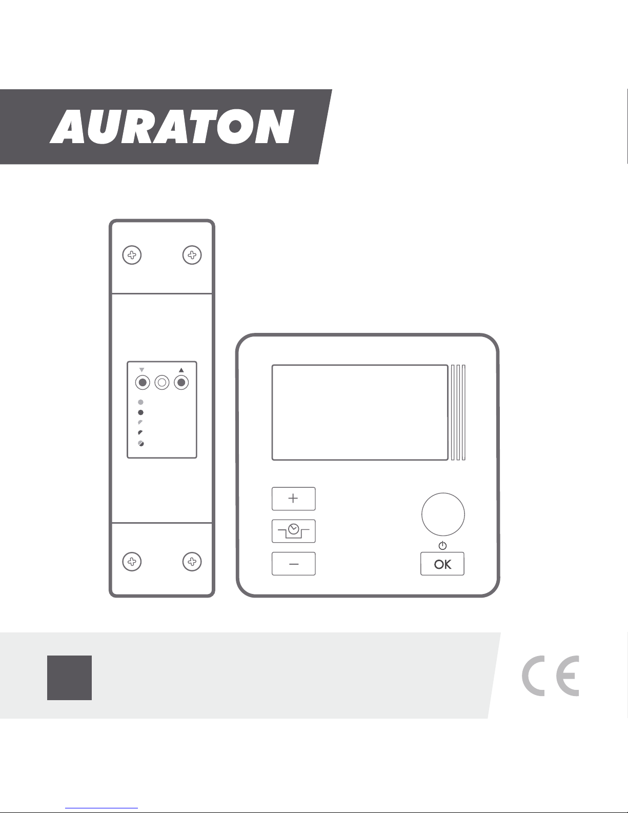
Wireless central heating pump controller
AURATON S03 RTH
The AURATON S03 RTH controller is tended for wireless control of a
central heating (CH) pump.
Before you start using the controller, please read this instruction
carefully.
3
APPLICATION
AURATON S03 RTH is intended for automatically switching on and off
circulation pumps depending on the temperature. The controller-
pump assembly forces the water to circulate in the central heating
system with a coal-fired boiler or a gas boiler. The controller's sensor
measures the temperature of the water on the supply side of the CH
system. In a CH system with a coal-fired boiler, the controller switches
off the circulation pump after the flame in the boiler is extinguished.
Pumping of water is not recommended when the flame is extinguished
because the air draft into the chimney causes faster cooling of the
water in the boiler faster than in the radiators. The optimum
temperature can be set on the controller's scale (most often 40 °C).
In a CH system with a gas boiler, the temperature set on the controller
must be lower than the temperature set on the CH boiler. If the
temperature is set on the controller above the dew point, it prevents
condensation in the boiler during the heating of the water in the CH
system.
The AntyStop (AS) system installed in the Auraton S03 RTH controller
prevents seizure of the rotor of an unused pump. Also, a built in
processor starts the pump every 14 days for 30 seconds after the
heating season is over. In order for the system to work after the heating
season, the controller must be switched on with the AS function active
at all times.
AntyStop system

2
Wireless central heating pump controller
AURATON S03 RTH
The AURATON S03 RTH controller is tended for wireless control of a
central heating (CH) pump.
Before you start using the controller, please read this instruction
carefully.
3
APPLICATION
AURATON S03 RTH is intended for automatically switching on and off
circulation pumps depending on the temperature. The controller-
pump assembly forces the water to circulate in the central heating
system with a coal-fired boiler or a gas boiler. The controller's sensor
measures the temperature of the water on the supply side of the CH
system. In a CH system with a coal-fired boiler, the controller switches
off the circulation pump after the flame in the boiler is extinguished.
Pumping of water is not recommended when the flame is extinguished
because the air draft into the chimney causes faster cooling of the
water in the boiler faster than in the radiators. The optimum
temperature can be set on the controller's scale (most often 40 °C).
In a CH system with a gas boiler, the temperature set on the controller
must be lower than the temperature set on the CH boiler. If the
temperature is set on the controller above the dew point, it prevents
condensation in the boiler during the heating of the water in the CH
system.
The AntyStop (AS) system installed in the Auraton S03 RTH controller
prevents seizure of the rotor of an unused pump. Also, a built in
processor starts the pump every 14 days for 30 seconds after the
heating season is over. In order for the system to work after the heating
season, the controller must be switched on with the AS function active
at all times.
AntyStop system

4
Description of the controller
LCD display
a temperature
increase button
On the front part of the enclosure there is a backlit LCD display and
four function buttons.
a button for the reduction
of the programmed
pump shutdown temperature mode
/ AntyStop mode
a confirmation
or controller
on/off button
a temperature
decrease button
źby pressing the button for a short time, you can
confirm the temperature setting
źby holding the button, you can switch the
controller on/off
5
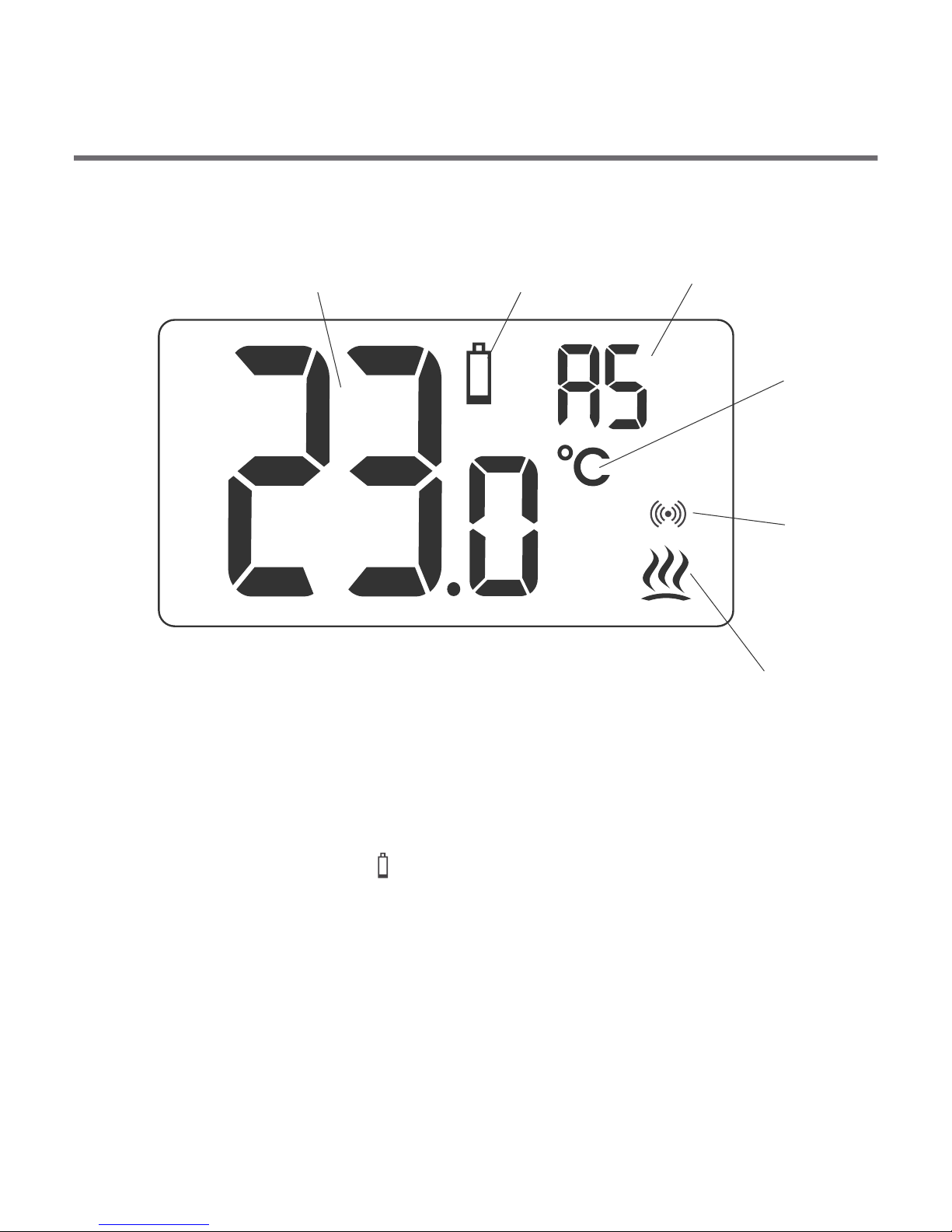
Display
1.Temperature
In the normal operation mode, the controller displays the
temperature in the room where it is installed.
2. Discharged battery ( )
The indicator is displayed when the permissible minimum battery
voltage level is exceeded. The battery must then be replaced as
soon as possible.
NOTE: In order to maintain the controller settings, the battery
replacement should take not more than 30 seconds.
1 2 3
4
5
6
4
Description of the controller
LCD display
a temperature
increase button
On the front part of the enclosure there is a backlit LCD display and
four function buttons.
a button for the reduction
of the programmed
pump shutdown temperature mode
/ AntyStop mode
a confirmation
or controller
on/off button
a temperature
decrease button
źby pressing the button for a short time, you can
confirm the temperature setting
źby holding the button, you can switch the
controller on/off
5
Display
1.Temperature
In the normal operation mode, the controller displays the
temperature in the room where it is installed.
2. Discharged battery ( )
The indicator is displayed when the permissible minimum battery
voltage level is exceeded. The battery must then be replaced as
soon as possible.
NOTE: In order to maintain the controller settings, the battery
replacement should take not more than 30 seconds.
1 2 3
4
5
6

3. AntyStop mode activation indicator
This mode prevents seizing of the rotor of an unused pump.
4. Temperature unit ( )
This indicates that the temperature is displayed in degrees
Celsius.
5. Activated pump indicator ( )
A pictogram that indicates the operating status of the pump. It is
displayed when the controlled device is switched on.
6. Transmission symbol ( )
Indicates communication with the receiver.
67
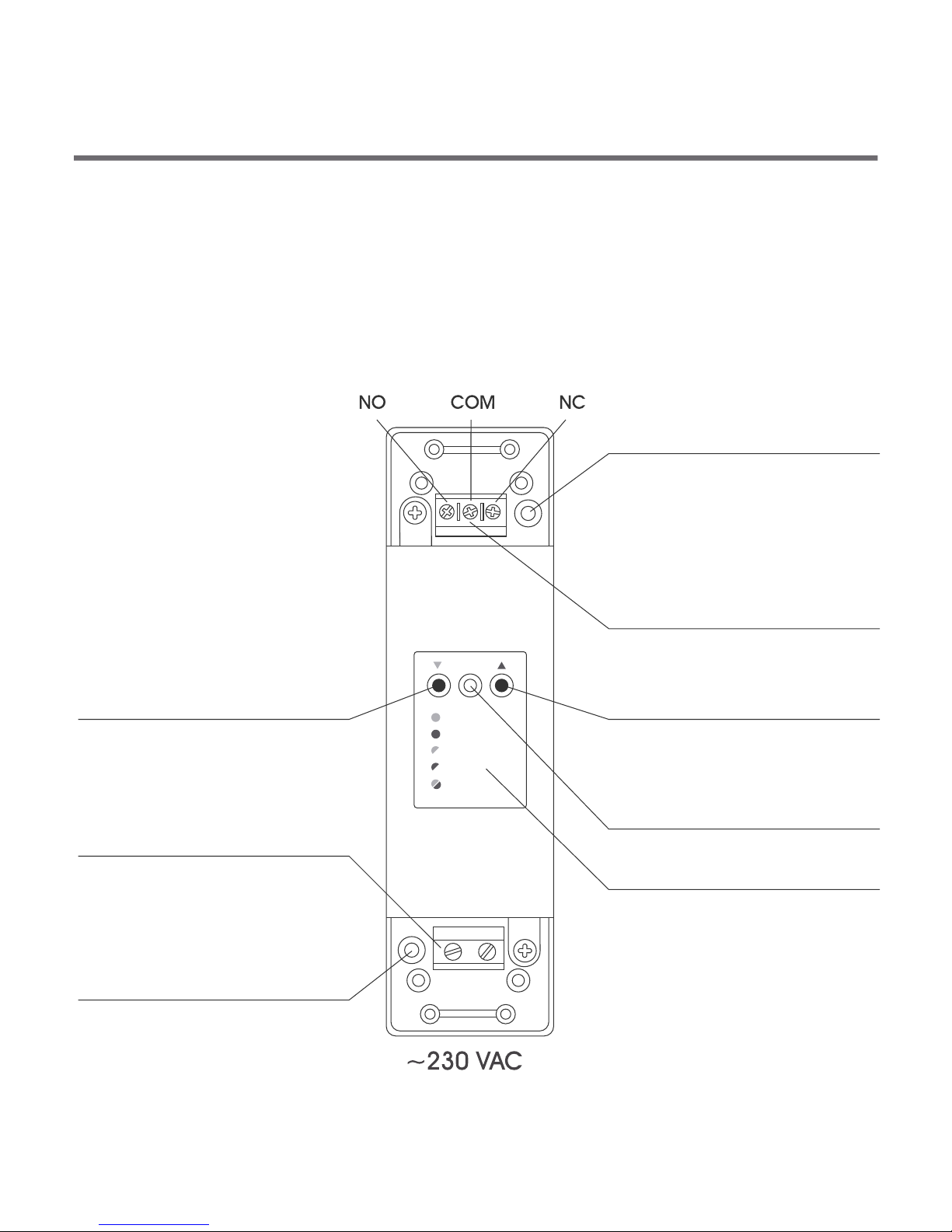
Description of the RTH receiver
The RTH receiver works with the wireless AURATON S03 controller. It
can work at the load equal to 16 A.
The receiver is installed at the CH pump.
OFF
ON
IN
OUT
ALARM
RESET
cable fixture
control connection terminal
button for unpairing devices
button for pairing devices
with the receiver
diode indicating
operation of the device
cable fixture - power supply
connection terminal
approx. 230 V AC
key/description
hole for the screw
fixing the receiver to the wall
hole for the screw
fixing the receiver to the wall
3. AntyStop mode activation indicator
This mode prevents seizing of the rotor of an unused pump.
4. Temperature unit ( )
This indicates that the temperature is displayed in degrees
Celsius.
5. Activated pump indicator ( )
A pictogram that indicates the operating status of the pump. It is
displayed when the controlled device is switched on.
6. Transmission symbol ( )
Indicates communication with the receiver.
67
Description of the RTH receiver
The RTH receiver works with the wireless AURATON S03 controller. It
can work at the load equal to 16 A.
The receiver is installed at the CH pump.
OFF
ON
IN
OUT
ALARM
RESET
cable fixture
control connection terminal
button for unpairing devices
button for pairing devices
with the receiver
diode indicating
operation of the device
cable fixture - power supply
connection terminal
approx. 230 V AC
key/description
hole for the screw
fixing the receiver to the wall
hole for the screw
fixing the receiver to the wall
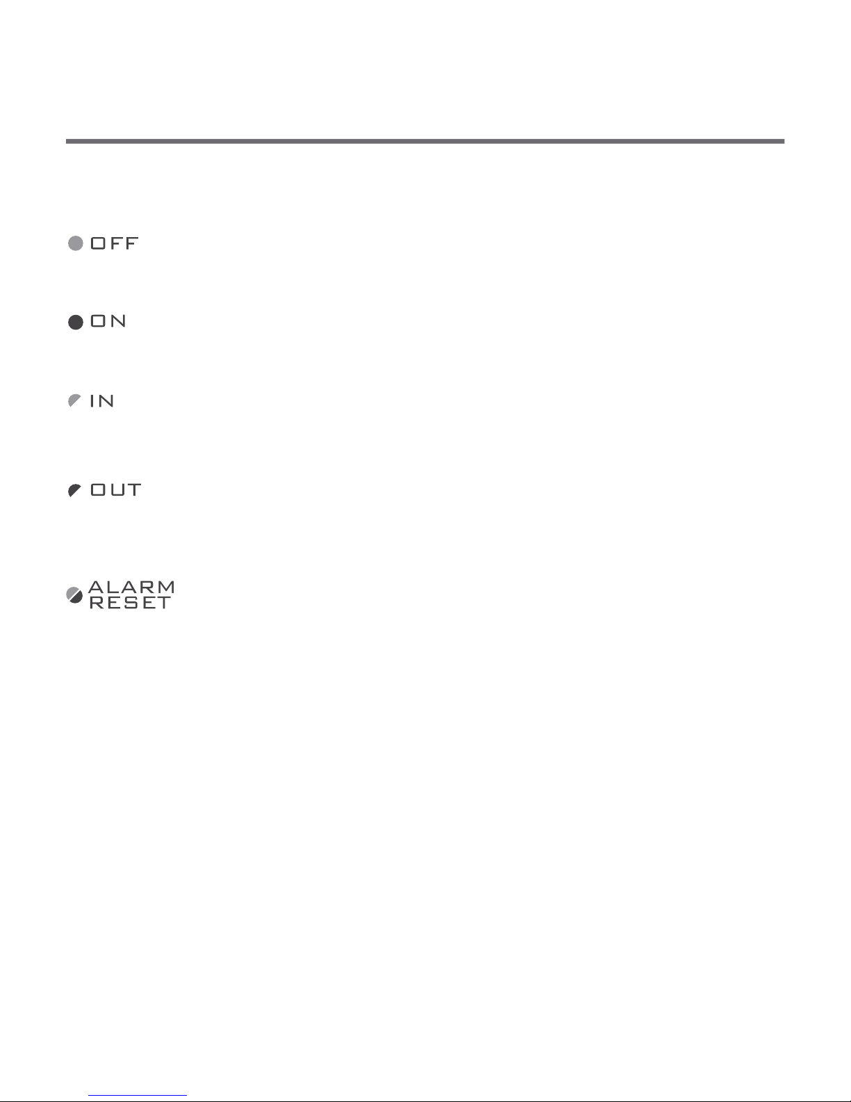
8
The diode is illuminated green - the operating device is
off (the COM and NC contacts are closed).
The diode is illuminated red - the operating device is on
(the COM and NO contacts are closed).
The diode is blinking green - the receiver is waiting for the
device to be paired - (chapter “Paring of a wireless
controller with the receiver”).
The diode is blinking red - the repeater is waiting for a
device to unpair - (chapter: “Unpairing the controller
from the receiver”).
The diode is blinking red and green alternately:
ALARM - the receiver’s connection with one of the paired
devices is broken - (chapter: “Special
situations”).
RESET - the receiver unpairs all the previously paired
devices - (chapter: “Unpairing all devices paired
with the receiver”).
Key - description of diode signaling in the receiver
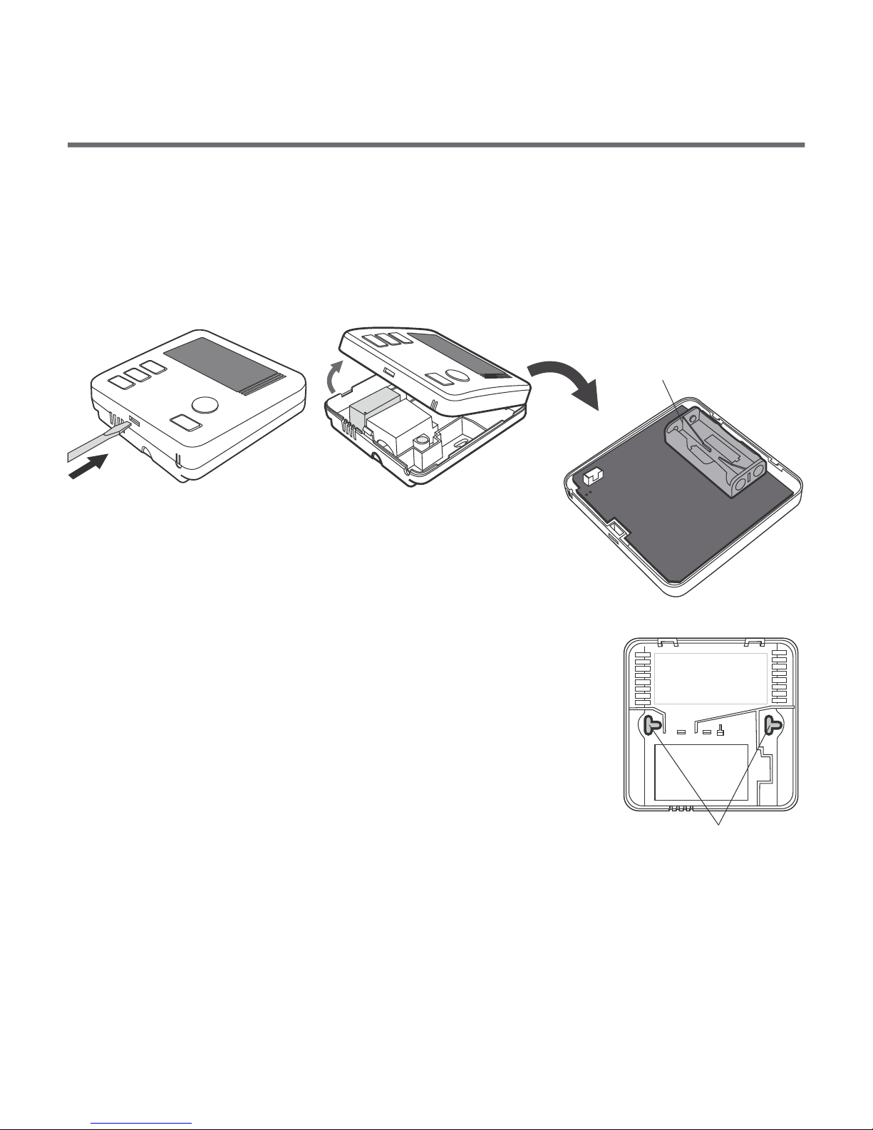
In order to mount the controller on a wall:
1. Take off the enclosure of the controller.
2. Drill two 6 mm diameter holes in the wall.
3. Put two wall plugs in the drilled holes.
4. Fasten the back part of the enclosure to the wall
using the screws provided with the set.
5. Put on the controller’s enclosure.
If the wall is made of wood, there is no need to use wall plugs. Only 2.7 mm
diameter holes (instead of 6 mm) should be drilled and the screws should be
driven directly into the wood.
9
Installation/replacement of batteries
The battery compartment can be found inside the controller, on the
front part of the enclosure. In order to install the batteries, take off
the enclosure.
battery compartment
- 2 x AAA 1,5 V batt.
Put two 1.5 V AAA batteries inside the battery
compartment, paying attention to the polarity of
the batteries.
Mounting the controller on a wall
a hole for
the fastening screw
NO COM NC
8
The diode is illuminated green - the operating device is
off (the COM and NC contacts are closed).
The diode is illuminated red - the operating device is on
(the COM and NO contacts are closed).
The diode is blinking green - the receiver is waiting for the
device to be paired - (chapter “Paring of a wireless
controller with the receiver”).
The diode is blinking red - the repeater is waiting for a
device to unpair - (chapter: “Unpairing the controller
from the receiver”).
The diode is blinking red and green alternately:
ALARM - the receiver’s connection with one of the paired
devices is broken - (chapter: “Special
situations”).
RESET - the receiver unpairs all the previously paired
devices - (chapter: “Unpairing all devices paired
with the receiver”).
Key - description of diode signaling in the receiver
In order to mount the controller on a wall:
1. Take off the enclosure of the controller.
2. Drill two 6 mm diameter holes in the wall.
3. Put two wall plugs in the drilled holes.
4. Fasten the back part of the enclosure to the wall
using the screws provided with the set.
5. Put on the controller’s enclosure.
If the wall is made of wood, there is no need to use wall plugs. Only 2.7 mm
diameter holes (instead of 6 mm) should be drilled and the screws should be
driven directly into the wood.
9
Installation/replacement of batteries
The battery compartment can be found inside the controller, on the
front part of the enclosure. In order to install the batteries, take off
the enclosure.
battery compartment
- 2 x AAA 1,5 V batt.
Put two 1.5 V AAA batteries inside the battery
compartment, paying attention to the polarity of
the batteries.
Mounting the controller on a wall
a hole for
the fastening screw
NO COM NC
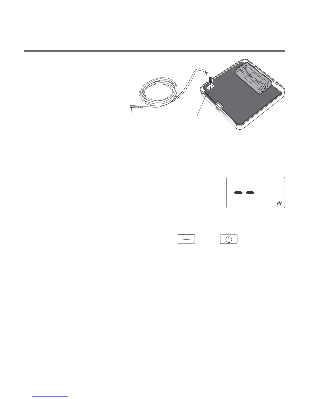
10
External
temperature
sensor
Terminal
block
External
temperature sensor
As a standard, after the battery is put in, the controller without a sensor
connected displays the temperature from the internal temperature sensor.
When the external temperature sensor is connected, the controller
automatically reads the values measured by that sensor.
If the external sensor is disconnected or defective, the
controller switches into the emergency mode (dashes are
shown as the temperature value) which results in
switching on the relay and, consequently, thecontrolled
device. In order to leave the emergency mode, the external
temperature sensor must be reconnected or the controller must be restarted
by simultaneously pressing and holding the and switches for
at least 5 seconds. After this procedure is completed, the controller displays
the temperature measured by the internal sensor.
[minus] [power]
Install the sensor on an uncovered outlet pipe connected to the CH boiler (as
close to the boiler as possible). Press the sensor against the tube using a
clamp. It is recommended to wrap the boiler pipe from the boiler to the sensor
with an insulation material.
If a coal-fired boiler and a gas-fired boiler work in the same CH system, the
sensor should be installed in a location where the two outlets merge and
must be insulated.
Mounting the sensor
11
OFF
ON
IN
OUT
ALARM
RESET
Fastening the RTH receiver
cover
NOTE !
When installing the receiver its power
supply must be disconnected. It is
recommended that the installation is
performed by a qualified specialist.
The permanent electrical system of
a building must include a breaker and
an overcurrent protection.
!
1. Take off protective covers from the lower
and upper part of the receiver.
2. Take off cable tie clamps from the lower and
upper part of the receiver.
3. Connect the heating device to the control
connection terminals of the receiver.
Proceed in accordance with the service
manual of the heating device. Most
commonly, the COM (common) and NO
(normally open) terminals.
4. Connect power supply conductors to the
power supply terminals of the receiver,
observing safety rules.
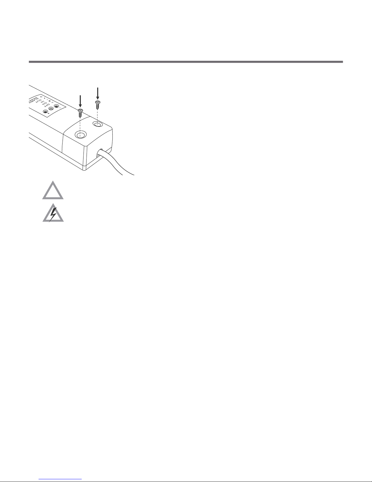
12
!
5. After connecting the conductors, they must be
secured with the cable tie clamps and reinstall
protective covers of the receiver.
To fasten the RTH receiver to the wall:
1) Remove protective covers from the lower and upper part of the regulator.
(See chapter: “Fastening the RTH receiver”).
2) On the wall, mark the location of holes for fastening screws.
3) In marked places, drill holes of a diameter corresponding to the bundled
wall plugs (5 mm).
4) Insert wall plugs into the drilled holes.
5) Screw in the RTH receiver to the wall with screws, making sure they hold
the receiver securely.
Fastening the RTH receiver to the wall
WARNING !
Cables supplied with the regulator are designed for conducting maximal
load of 2.5 A. If devices to be connected require more power, the cables need
to be replaced with cables of the appropriate cross-sectional area.
13
NOTE: If the wall is wooden, there is no need to use wall plugs. In such a
case, drill two holes 2.7 mm in diameter instead of 5 mm, and screw the
screws directly into the wood.
NOTE: The RTH receiver cannot be placed in metal containers (e.g. an
assembly box, a metal enclosure of a heater) in order to not to interfere with
its operation.
OFF
ON
IN
OUT
ALARM
RESET
hole for fastening
the receiver to the
wall with a screw
hole for fastening
the receiver to the
wall with a screw

14
Pairing the wireless temperature regulator
with the RTH receiver
NOTE: The wireless temperature regulator sold with the receiver is
already paired. Devices sold separately require “pairing”.
3. A properly completed pairing process is signalled by the LED on the receiver
no longer flashing green and the receiver reverting back to normal
operation.
In the event of an error during the pairing process, repeat steps 1 and 2.
Should more errors occur, deregister all devices by executing the RESET
function of the receiver (see “RESET - Deregistering all devices paired with
the receiver”) and attempt to pair the device again.
NOTE: One receiver can have only one temperature regulator assigned.
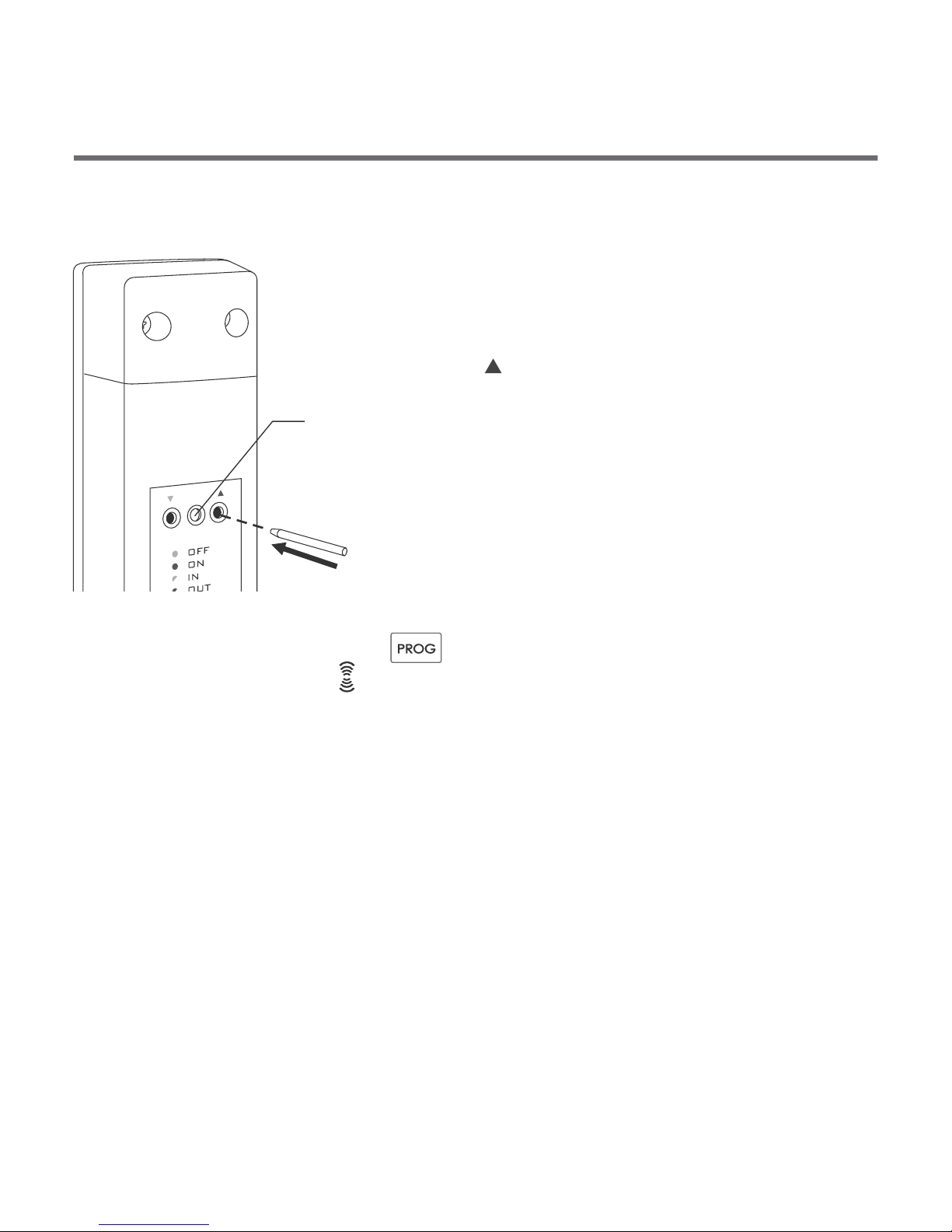
1. The process of pairing the regulator with the
receiver is initiated by pressing the left
pairing button (marked with a green triangle
- ) on the receiver and holding it for at least
2 seconds, until the LED starts flashing
green, and then releasing the button.
The AURATON RTH receiver waits for pairing
for 120 seconds. After that time, it
automatically returns back to normal
operation.
2.
transmission symbol ( ) appears on the display. Release the button - the
regulator transmits the pairing signal for 5 seconds.
On the regulator, press the button and hold it for 5 seconds until the {prog}
{}
LED
15
Deregistering the regulator from the receiver
1.Deregistering the temperature controller from
the receiver is initiated by pressing the right
deregistering button (marked with a red
triangle - ) on the receiver and holding it for at
least 2 seconds, until the LED starts flashing
red, and then releasing the button.
The AURATON RTH receiver waits for
deregistering for 120 seconds. After that time,
it automatically returns back to normal
operation.
LED
3. A properly completed deregistering process is signalled by the LED on the
receiver no longer flashing red and the receiver reverting back to normal
operation.
In the event of an error during the deregistering process, repeat steps
1 and 2. Should more errors occur, deregister all paired devices (see “RESET -
Deregistering all devices paired with the receiver”) and attempt to pair the
device again.
2.
transmission symbol ( ) appears on the display. Release the button - the
regulator transmits the pairing signal for 5 seconds.
On the regulator, press the button and hold it for 5 seconds until the [prog]
14
Pairing the wireless temperature regulator
with the RTH receiver
NOTE: The wireless temperature regulator sold with the receiver is
already paired. Devices sold separately require “pairing”.
3. A properly completed pairing process is signalled by the LED on the receiver
no longer flashing green and the receiver reverting back to normal
operation.
In the event of an error during the pairing process, repeat steps 1 and 2.
Should more errors occur, deregister all devices by executing the RESET
function of the receiver (see “RESET - Deregistering all devices paired with
the receiver”) and attempt to pair the device again.
NOTE: One receiver can have only one temperature regulator assigned.
1. The process of pairing the regulator with the
receiver is initiated by pressing the left
pairing button (marked with a green triangle
- ) on the receiver and holding it for at least
2 seconds, until the LED starts flashing
green, and then releasing the button.
The AURATON RTH receiver waits for pairing
for 120 seconds. After that time, it
automatically returns back to normal
operation.
2.
transmission symbol ( ) appears on the display. Release the button - the
regulator transmits the pairing signal for 5 seconds.
On the regulator, press the button and hold it for 5 seconds until the {prog}
{}
LED
15
Deregistering the regulator from the receiver
1.Deregistering the temperature controller from
the receiver is initiated by pressing the right
deregistering button (marked with a red
triangle - ) on the receiver and holding it for at
least 2 seconds, until the LED starts flashing
red, and then releasing the button.
The AURATON RTH receiver waits for
deregistering for 120 seconds. After that time,
it automatically returns back to normal
operation.
LED
3. A properly completed deregistering process is signalled by the LED on the
receiver no longer flashing red and the receiver reverting back to normal
operation.
In the event of an error during the deregistering process, repeat steps
1 and 2. Should more errors occur, deregister all paired devices (see “RESET -
Deregistering all devices paired with the receiver”) and attempt to pair the
device again.
2.
transmission symbol ( ) appears on the display. Release the button - the
regulator transmits the pairing signal for 5 seconds.
On the regulator, press the button and hold it for 5 seconds until the [prog]

17
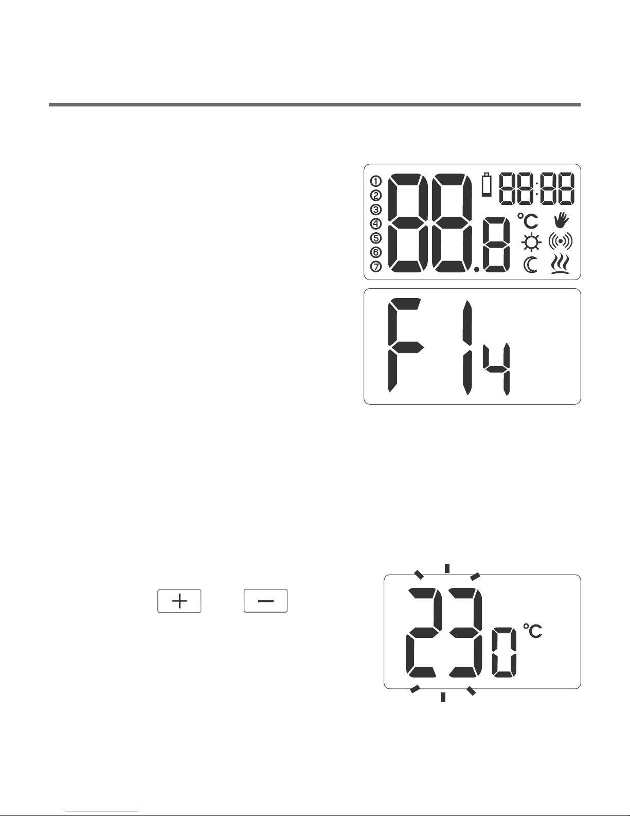
Temperature setting
NOTE: The first time any function button is pressed, the illumination
is always switched on first and only then the button's function is
activated.
In order to set the temperature in the
normal operation mode:
1. Press the or button.
The segment that shows the
temperature goes into the edition
mode and starts blinking.
[plus] [minus]
Switching the controller on for the first time
After the batteries are properly
installed in the battery compartment,
the LCD display shows all segments for
one second (a display test) and then it
shows the software version.
After a moment, the current
temperature in the room is displayed.
Then the controller is ready for
operation.
16
RESET - Deregistering all devices paired with
the receiver
In order to deregister all devices paired with the
receiver, simultaneously press both the pairing
and the deregistering button ( and ) and hold
them for at least 5 seconds until the LED flashes
alternating red and green. Then release both
buttons.
A properly completed process of deregistering all
devices is signalled after approx. 2 seconds by
the LED colour changing to green and then
switching it off for a short period of time.
LED
NOTE: If after executing the RESET function the RTH receiver is disconnected
from power supply and then connected again, the receiver will automatically
enter “pairing” mode for 120 seconds. A newly purchased RTH receiver
without any factory-paired devices (i.e. not the one bundled with the
regulator) will behave the same way.
Signalling operation and reception of data packet
Each radio transmission received by the AURATON RTH receiver from the
paired device is signalled by a temporary change of LED colour to orange.
Switching on the relay is signalled by the LED lit red, whereas switching it off is
signalled by the LED lit green.
17
Temperature setting
NOTE: The first time any function button is pressed, the illumination
is always switched on first and only then the button's function is
activated.
In order to set the temperature in the
normal operation mode:
1. Press the or button.
The segment that shows the
temperature goes into the edition
mode and starts blinking.
[plus] [minus]
Switching the controller on for the first time
After the batteries are properly
installed in the battery compartment,
the LCD display shows all segments for
one second (a display test) and then it
shows the software version.
After a moment, the current
temperature in the room is displayed.
Then the controller is ready for
operation.
16
RESET - Deregistering all devices paired with
the receiver
In order to deregister all devices paired with the
receiver, simultaneously press both the pairing
and the deregistering button ( and ) and hold
them for at least 5 seconds until the LED flashes
alternating red and green. Then release both
buttons.
A properly completed process of deregistering all
devices is signalled after approx. 2 seconds by
the LED colour changing to green and then
switching it off for a short period of time.
LED
NOTE: If after executing the RESET function the RTH receiver is disconnected
from power supply and then connected again, the receiver will automatically
enter “pairing” mode for 120 seconds. A newly purchased RTH receiver
without any factory-paired devices (i.e. not the one bundled with the
regulator) will behave the same way.
Signalling operation and reception of data packet
Each radio transmission received by the AURATON RTH receiver from the
paired device is signalled by a temporary change of LED colour to orange.
Switching on the relay is signalled by the LED lit red, whereas switching it off is
signalled by the LED lit green.

The controller has the functionality of reduction of the
pump shutdown temperature. When the setting is e.g.
40°C and the reduction is set to 1°C, the pump shuts
down at the temperature of 39°C. If the reduction is set to 5°C, the
pump shuts down at 35°C.
In order to set the reduction temperature,
press the button (the factory setting
is 3°C).
Each time the button is pressed, the
temperature setting changes by 1°C in a loop from 1°C to 5°C.
Confirm the selection by pressing the button.
[CLOCK]
[OK]
[OK]Note: If the button is not press, the controller returns to the normal
operation mode after 10 seconds.
18
2. Use the and buttons to set the desired
temperature in the room with the accuracy of 1°C.
3. Confirm the selection by briefly pressing the button.
[plus] [minus]
[OK]
Setting the “reduction of the programmed
pump shutdown temperature”
In order to switch the AntyStop mode on,
press and hold the button pressed
for 3 seconds.
The display shows (the function is
active).
[clock]
[AS]
19
Switching the “AntyStop” mode on/off
The AntyStop mode prevents seizing of the rotor of an unused pump.
Also, a built in processor starts the pump every 14 days for 30 seconds
after the heating season is over.
In order for the system to work after the heating season, the
controller must remain switched on with the AntyStop function
active.
Comments
źThe controller may be switched on or off at any time by briefly
pressing the button.
źThe first time any function button is pressed, the illumination is
always switched on first and only then the button's function is
activated.
źWhen programming any function, if no buttons are pressed for
10 seconds, this is equivalent to pressing the button.
[OK]
[OK]

20
Additional functions
źAfter batteries are installed, the controller displays the
temperature from the external temperature sensor.
źWhen the external sensor is connected (the terminal block is
located under the enclosure), the controller automatically takes
the readings from that sensor.
źIf the external sensor is disconnected or defective, the
controller goes into the emergency mode (dashes are shown as
the measured temperature), which results in the CH pump
shutting down until the defect is eliminated. This is intended to
p ro te c t t h e h e a t i n g sy s t e m f r o m o v e r h e a t i n g .
In order to leave the emergency mode, connect the external
temperature sensor back or reset the controller by taking out
the battery until the display switches off. After this procedure is
completed, the controller displays the temperature measured
by the internal sensor.
21
Wiring diagram showing the connection
of the CH pump to the RTH receiver
approx. 230 V AC
L N
L
N
max. approx. 230 V
central
heating
boiler
temperature
sensor
pump
controller
RTH receiver
Table of contents
Other AURATON Thermostat manuals

AURATON
AURATON Libra User manual

AURATON
AURATON 1300 User manual

AURATON
AURATON T-1 RT User manual

AURATON
AURATON 200 RTH User manual

AURATON
AURATON Libra User manual

AURATON
AURATON Tucana User manual

AURATON
AURATON 2020 User manual

AURATON
AURATON Tucana User manual

AURATON
AURATON 2005 TX User manual

AURATON
AURATON R30 RT User manual


Popular Thermostat manuals by other brands

Conrad
Conrad 61 88 88 operating instructions

Jackson Systems
Jackson Systems Wireless Comfort WCT-32 installation manual

Carrier
Carrier 33CS400-01 installation instructions

Tetra
Tetra HT 25-300 Instructions for use

Bticino
Bticino LIVING L4448 instruction sheet

Vostermans Ventilation
Vostermans Ventilation Mf-Net SEA-3N installation instructions


