WAC Lighting GEOS F-068L User manual

GEOS
Installation Instructions
works with the
Google Assistant

Please read and save these
instructions before installation

For all questions about your ceiling fan please read all
included instructions, installation procedures, trouble-
shooting guidelines and warranty information before
starting installation.
For fast service have the following information below
when you call:
For missing parts or general inquiries
call our trained technical sta at:
• Model Name and Number
• Part Number and Part Description
• Date Of Purchase and Purchase Location
Email: [email protected]
Or live chat at www.waclighting.com
Email: fansupport@waclighting.com
1-800-526-2588 option 01-800-526-2588 option 3
MON-FRI 8AM-8PM EST MON-FRI 8AM-8PM EST
GENERAL INQUIRIES FAN SUPPORT
DO NOT RETURN TO STORE

SAFETY RULES
To reduce the risk of electric shock, ensure electricity has been turned o at
the circuit breaker before beginning.
All wiring must be in accordance with the National Electrical Code“ANSI/
NFPA 70” and local electrical codes. Electrical installation should be
performed by a licensed electrician.
The fan must be mounted with a minimum of 7 ft. (2.1m)
clearance from the trailing edge of the fan blades to the oor
and a minimum of 1.5 ft (0.5m) from the edge of the fan blades to the
surrounding walls.
Never place objects in the path of the fan blades.
To avoid personal injury or damage to the fan and
other items, please be cautious when working around
or cleaning the fan.
To avoid electrical shock or damage to the motor or nish, do not use water
or chemicals when cleaning the fan or fan blades. A dry cloth or lightly
dampened cloth will be suitable for most cleaning.
After making electrical connections, spliced conductors should be turned
upward and pushed carefully up into the outletbox. The wires should be
spread apart with the grounded conductor and the equipment-grounding
conductor on one side of the outletbox, and the ungrounded conductor on
the other side of the outletbox.
All set screws must be checked and re-tightened where necessary before
installation.
For operation, maintenance, and troubleshooting information, visit http://waclighting.com/fan-support/

02 SAFETY RULES
WARNING: Do not install or use your fan if any part(s) is/are damaged or
missing. This product is designed for use only with the supplied parts and/
or accessories designated for use with this product by WAC. Substitution of
parts or accessories not designated for use with this product by WAC could
result in personal injury or property damage and will void the warranty.
Contact an authorized dealer or the manufacturer if any parts are damaged
or missing.
WARNING: To reduce the risk of electric shock, this fan must
be installed and operated with the supplied wall control, or controlled from
the WAC app.
WARNING: Do not use power tools to assemble or install your fan. Using
power tools can result in improper assembly which can lead to noise or fan
damage,personal injury or property damage.
WARNING: To reduce the risk of personal injury, do not bend the
blade arms when installing the brackets, balancing the blades or cleaning
the fan.
WARNING: Do not insert foreign objects between rotating fan blades.
WARNING: Do not operate fan unless fan blades are in place.
Noise and fan damage can occur
WARNING: This appliance is not intended for use by young
children without supervision.
WARNING: To reduce the risk of re, electric shock, personal injury or damage
to the fan or other items, the outletbox and support structure must be
securely mounted and capable of reliably supporting a minimum of 35 Ibs
(15.9 kg). Use only UL/cUL listed outletboxes marked “FOR FAN SUPPORT.” Use
only the screws and washers provided with the outletbox.
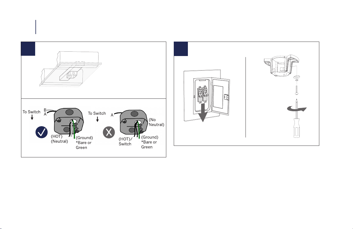
CAUTION: Before assembling your fan, refer to the “Making
the Electrical Connections“ section. If you feel you do not have
enough wiring knowledge or experience, have your fan installed
by a licensed electrican.
NOTE: Before servicing or cleaning the fan, switch power o at
the circuit breaker.

This WAC Smart Fan is:
DC
MOTOR
The WAC app synchronizes seamlessly with smart home devices you already own
GET SMART
works with the
Google Assistant
WALL CONTROL
WC20-WT
Optional accessory
sold separately
6 fan speeds
Dims light to 1%
ON/OFF
APP DOWNLOAD
Available for purchase on
the Google Pay and App Store
Quiet, reliable, and up to 70%
more ecient than AC motor fans
Wet Rated and durably nished
for interior and exterior use
Wi-Fi and Bluetooth enabled
for unlimited control
Wet location-listed to the strictest
UL/cUL safety regulations
Compatible with our WAC app
Coordinate with smart devices
for voice-activated control
REMOTE CONTROL
RC20-WT
Included with
each fan
6 fan speeds
Dims light to 1%
ON/OFF

Package Contents
Mounting Options
Installing the Mounting Bracket
Attaching the Fan Blades
Hanging the Fan
Making the Electrical Connections
Installing the Optional Wall Control
Finishing the Installation
Installing the Decorative Plate and Lower Decorative Ring
Installing the Luminaire Module
Controlling the Fan
Reset
Application
Accessories
Troubleshooting
9.
10.
10.
11.
12.
14.
15.
17.
18.
19.
21.
24.
25.
27.
29.
4
7
8
9
10
11
12
13
14
15
16
5
5
6
7
TABLE OF CONTENTS

F-068L
8
Electrical tape
Phillips screwdriver Step ladder Wire cutters
NOTE: Before discarding packaging materials, be certain all parts have been removed.
NOTE: Place the parts from the hardware bag into a small container to keep them from being lost.
Hanging Weight: 28lbs
MAC ID
03 TOOLS & MATERIALS REQUIRED
IMPORTANT: Please make note of the MAC ID on the receiver and keep it in a safe place.

9F-068L
NOTE: ** denotes nish code of fan
1
9
5
3
8
5
4
12
2
7
10
11
Canopy Ring
RPL-CAN-CYL-**
Luminaire Plate & Lower
Decorative Ring
Coupling
Cover
Hardware Bag
RPL-F068-PARTS
Canopy
RPL-CAN-CYL-**
Motor Housing
Fan Blade
RPL-F068-60-BD-**
Remote Control
RC20-WT
PACKAGE CONTENTS 04
Downrod
Assembly
RPL-HGR-ASM-**
Mounting
Bracket
RPL-HGR-ASM-**
Glass Shade
RPL-F068-GLA
Luminaire Module
F4IN-120V-R1-30
Receiver
F-R3-068-060
13
A: Junction Box
#10x38mm Pan Head Phillip Screws(2)
Ø5*14*1mm Flat Washers (2)
3/16” Star Washers (2)
B: Blade Screw and Washers
3/16*12 mm Philip Washer Heads (10)
Ø5*14*1mm Flat Washers (10)
C: Safety Cable
Ø6.5x19x2mm Flat Washer (1)
Spring Washer (1)
Wood Screws(1)
D: Wire Connectors (8)
E: Luminaire Module screws
5/32” x 1/4mm (4)
(included with receiver)

F-068L
10
12
05 MOUNTING OPTIONS INSTALLING THE MOUNTING BRACKET
Standard Ceiling
1. Disconnect power at the breaker.
2. Remove 1 set screw from mounting bracket and set aside for
use in Finishing the Installation.
3. Pass supply wires through mounting bracket and secure to
outlet box.
4. Secure the mounting bracket to the ceiling with the screws
and washers provided with your outlet box.
Caution: Remember to disconnect
the power at the circuit breaker.
CAUTION: To prevent electrical shock, ensure electricity has been
turned o at the circuit breaker before beginning.
Figures 1 and 2 are examples of dierent ways to mount the space
outlet box. Use Ahardware if needed.

11F-068L
31. Slide blade into motor assembly.
2. Secure blade with blade attachment screws and washers -
repeat for remaining blades. Use Bhardware.
ATTACHING THE FAN BLADES 06
15~20°

F-068L
12
54
1. Remove screw from hanger ball. Remove hanger ball
and cross pin.
2. Loosen 2 screws, clevis pin and cotter pin.
1. Install coupling cover, canopy screw ring, canopy and
downrod assembly into motor housing as shown.
07 HANGING THE FAN

13F-068L
67
HANGING THE FAN 07
1. Align downrod and motor collar holes, re-insert pins and screws.
2. Slip up canopy and canopy screw cover. Re-install hanger ball
with cross pin in correct place.
1. Seat all into the mounting bracket. Rotate until ball drops and
locks into hanger bracket screw.

14
9Outlet Box
Hanger Ball & Downrod
8
07 HANGING THE FAN MAKING THE ELECTRICAL CONNECTIONS
1. Secure the safety cable into the structure beams using the
wood screw, washers, and spring washers provided.
NOTE: Safety cable is required for all ceiling fan installations in
Canada. Safety cable is required for ceiling fan and light (combo)
installations over 35 lbs. in both ush and downrod models in the
United States.
2. Slide receiver into place with the at side facing up.
Use Chardware.
1. Connect the labled wires from fan to the corresponding wires
on the receiver. Use Dhardware.
2. Connect the labeled wires from the outlet box to the
corresponding wires on the receiver.
After making electrical connections, spliced connectors should be
turned upward and pushed carefully up into the outlet box. The
wires should be spread apart with the grounded conductor and the
equipment-grounding conductor on one side of the outlet box and
ungrounded connector on the other side of the outlet box. Secure
all connections with wire nuts and electrical tape. Failure to do so
may result in damage to the electronics.

15F-068L
10
NOTE:Wall control not included. A Bluetooth wall control accessory can be purchased separately.
NOTE: For multi-location wiring, skip to the next step.
1. Connect the green wire marked“GROUND”from the wall control to the copper wire from the wall outletbox that feeds back to the circuit
breaker – important for proper fan function.
2. Connect the black wire marked “LINE IN” from the wall control to the black LINE VOLTAGE wire from the wall outletbox that feeds back to the
circuit breaker.
3. Connect the red wire from the wall control to the black wire from the wall outletbox that feeds up to the fan.
4. Connect the white wire from the wall control to the white (neutral) wire from the wall outletbox.
5. Carefully tuck the wire connections inside the outletbox. Secure the wall control with the two (2) wall control screws provided.
6. Attach the wall mounting plate over the wall switch and secure with the two (2) wall mounting plate screws provided.
7. Fasten the wall plate to the wall mounting plate.
INSTALLING THE OPTIONAL WALL CONTROL 08

F-068L
16
1. Install the wall control using the wiring diagram above.
2. Individually pair each of the wall controls with the fan receiver using the pairing instruction.
08 INSTALLING THE OPTIONAL WALL CONTROL
11
Wall Control 1 Wall Control 2 Wall Control 3

17F-068L
1312
1. Secure wire connectors with supplied wire ties.
2. Install canopy to mounting bracket with the screw
removed in section 2.
1. Install canopy screw ring as shown.
FINISHING THE INSTALLATION 09

F-068L
18
14 15
10 INSTALLING THE LUMINAIRE PLATE AND LOWER DECORATIVE RING
1. Remove 1 of 3 screws from the mounting ring and loosen the
others (do not remove).
1. Twist and lock the luminaire plate & lower decorative ring into place
by following the arrows above.
2. Using the screw from the previous step, install the
luminaire plate and lower decorative ring

19F-068L
18
INSTALLING THE LUMINAIRE MODULE 11
1. Use the 3 screws located in the luminaire module screw bag to
install the luminaire module to the adapter plate.
Use Ehardware.
1. Connect the white wire connectors from the luminaire module
to the white wire of the fan. Follow same procedure with blue
wire connectors.
17

F-068L
20
19
11 INSTALLING THE LUMINAIRE MODULE
1. Install glass shade rmly without over-tightening.
Glass Light Shade
Table of contents
Other WAC Lighting Fan manuals

WAC Lighting
WAC Lighting CLEAN User manual

WAC Lighting
WAC Lighting Clean F-003 User manual

WAC Lighting
WAC Lighting MOCHA User manual

WAC Lighting
WAC Lighting Mocha XL F-064 User manual

WAC Lighting
WAC Lighting San Francisco F-081L User manual

WAC Lighting
WAC Lighting ORB F-004 User manual

WAC Lighting
WAC Lighting AELLA User manual

WAC Lighting
WAC Lighting F-001-MW User manual

WAC Lighting
WAC Lighting Blitzen F-060L User manual