TGW NBC User manual

NBC, TGW Nitta Belt Welding
Instructions
NBC Full Welding Instruction with
Nitta Blue Urethane Belt
P/N: 1207439
Date: 09/13/2019

TGW
P/N 1207439 Rev Date 09/13/2019 Page 2of 30
CONTENTS
INTRODUCTION............................................................................................................. 3
PURPOSE ..................................................................................................................... 3
SCOPE ......................................................................................................................... 3
TGW SAFETY INFORMATION....................................................................................... 4
WARNINGS AND SAFETY INSTRUCTIONS .......................................................................... 4
TGW SYSTEMS RECOMMENDED STANDARDS FOR CONVEYORS........................................ 5
TGW SAFETY RECOMMENDATION .................................................................................. 6
NBC CONVEYOR PREPARATION................................................................................. 7
FINGER PUNCH PROCESS ........................................................................................ 11
NBC WELD INSTRUCTIONS ....................................................................................... 15
TGW KITS & REPLACEMENT PARTS......................................................................... 22
TROUBLESHOOTING – NITTA CORPORATION ........................................................ 24
AIR BUBBLES .............................................................................................................. 24
IMPROPER BELT WELDING ........................................................................................... 27
WORKS CITED............................................................................................................. 29
TGW SYSTEMS INFORMATION.................................................................................. 30
History – Revision Changes
Revision Date Description
9/13/2019 Add caution note to use only TGW welder equipment
06/27/2019
Changed belt overlap length. NBC-150-AT from 36” to 18” and added 500-AT
to be 36”.

TGW
P/N 1207439 Rev Date 09/13/2019 Page 3of 30
INTRODUCTION
PURPOSE
This manual contains the instructions to properly weld a Nitta belt for use with TGW
NBC flat belt conveyor. These instructions use the TGW Nitta belt Finger Punch and
Weld Press. TGW recommends watching the enclosed flash drive video instruction
along with all TGW or Nitta manuals before repairs.
SCOPE
The purpose is to obtain strong, consistent belt joints in a safe and efficient manner.
To accomplish this, these instructions must be followed closely.
For more TGW conveyor information:
Visit www.tgw-conveyor.com for more maintenance videos and TGW IOM manuals.
WARNING:
•Use Only TGW Nitta belt welder and punch equipment for TGW Nitta belt
splice/welding. Non-TGW Nitta belt welding or punch equipment is not
compatible with the TGW Nitta belt!
CAUTION
TGW
P/N 1207439 Rev Date 09/13/2019 Page 4of 30
TGW SAFETY INFORMATION
WARNINGS AND SAFETY INSTRUCTIONS
Failure to follow the instructions and
cautions throughout this manual and
warning labels on the conveyor may
result in injury to personnel or damage
to the equipment.
Your TGW Systems conveyor is
powered by a motor and can be
stopped only by turning off electrical
power to the motor. As with all
powered machinery, the drive-related
components – including sprockets,
chains, shafts, universal joints, and
pneumatic devices – can be
dangerous. We have installed or
provided guards to prevent accidental
contact with these parts, along with
warning labels to identify the hazards.
Special attention must be paid to the
following areas of this manual:
•Indicates a potentially
hazardous situation,
which, if not avoided,
could result in death or
serious injury.
•Indicates a situation, which, if not
avoided, could result in property
damage.
WARNING
CAUTION
TGW
P/N 1207439 Rev Date 09/13/2019 Page 5of 30
TGW SYSTEMS RECOMMENDED STANDARDS FOR
CONVEYORS
TGW Safety Recommendation
For additional safety information:
TGW agrees to the following safety instruction or
guidelines listed within this manual. This is not to
conflict with your state or legal requirements.
TGW Recommends for maintenance or repair
purposes, to incorporate a lock out or tag
procedure. To ensure all starting devices, prime
movers, or powered accessories are off before
attempting to maintenance or repair.
The procedures below are designed to protect
everyone involved with the conveyor against an
unexpected restart. To include understanding of
potential hazard of stored energy, which can exist
after the power source is locked out.
For additional information, refer to the latest issue
of ANSI Z244.1, American National Standard for
Personnel Protection −Lockout/Tagout of Energy
Sources− Minimum Safety Requirements.
http://www.ansi.org/
OSHA 29CRF Part 1910.147 “Control of
Hazardous Energy Sources (Lockout/Tagout)”,
which includes requirements for release of stored
energy and OSHA Safety and Health Regulations
for Construction 1926.555 Conveyors
https://www.osha.gov/
Conveyor Design and Safety Guidelines
A safety risk evaluation is required for all of our
standard equipment. The safety risk evaluation
considers every potential hazard on the
conveyor, weighs the probability and the severity
of the potential injury, and addresses methods of
mitigation to make the risk of injury either low or
negligible. We use the ANSI B11 TR3 standards
for all of our risk evaluation. In addition, all of our
equipment is designed to comply with the
following national and industry standards:
•ANSI Z535.1 – Safety Color Code
•ANSI Z244.1 – Lockout/Tagout of Energy
Sources
•ASME B15.1 – Safety standard for
Mechanical Power Transmission Apparatus
•ASME B20.1 – Safety standard for
Conveyors and Related Equipment
•CEMA – Safety Standards and Labels
•OSHA 1910.147 – The Control of Hazardous
Energy
•OSHA 1910.212 - General Requirements for
all Machines
•OSHA 1910.95 – Occupational Noise
Exposure
•Definitions:
•ANSI = American National Standard Institute
•ASME = American Society of Mechanical
Engineers
•CEMA = Conveyor Equipment Manufacturers
Association
•OSHA = Occupational Safety and Health
Administration
•Safety: Always lock out power source and follow recommended
safety procedures.
WARNING

TGW
P/N 1207439 Rev Date 09/13/2019 Page 6of 30
TGW SAFETY RECOMMENDATION
TGW agrees to the following safety instruction or guidelines listed within this manual.
This is not to conflict with your state legal requirements.
TGW Recommends for maintenance or repair purposes, to incorporate a lock out or
tag procedure. To ensure all starting devices, prime movers, or powered accessories
are off before attempting to maintenance or repair.
The procedures below are designed to protect everyone involved with the conveyor
against an unexpected restart. To include understanding of potential hazard of stored
energy, which can exist after the power source is locked out.
For additional information, refer to the latest issue of ANSI Z244.1, American
National Standard for Personnel Protection −Lockout/Tagout of Energy
Sources− Minimum Safety Requirements. http://www.ansi.org/
OSHA 29CRF Part 1910.147 “Control of Hazardous Energy Sources
(Lockout/Tagout)”, which includes requirements for release of stored energy and
OSHA Safety and Health Regulations for Construction 1926.555 Conveyors
https://www.osha.gov/
•Pay attention to the safety instructions!
•Prior to working at or in the immediate vicinity of the system
it is recommended that you make yourself familiar with the
safety instructions included in the present document!
•TGW recommends reading all manuals supplied by TGW
or Nitta Corporation. https://www.nitta.com/
•TGW recommends only trained and maintenance personal
for conveyor repairs.
•Do not use tools or equipment stated in this manual for
other application.
•Do not dismantle or remodel equipment or tools under any
circumstances.
WARNING
TGW
P/N 1207439 Rev Date 09/13/2019 Page 7of 30
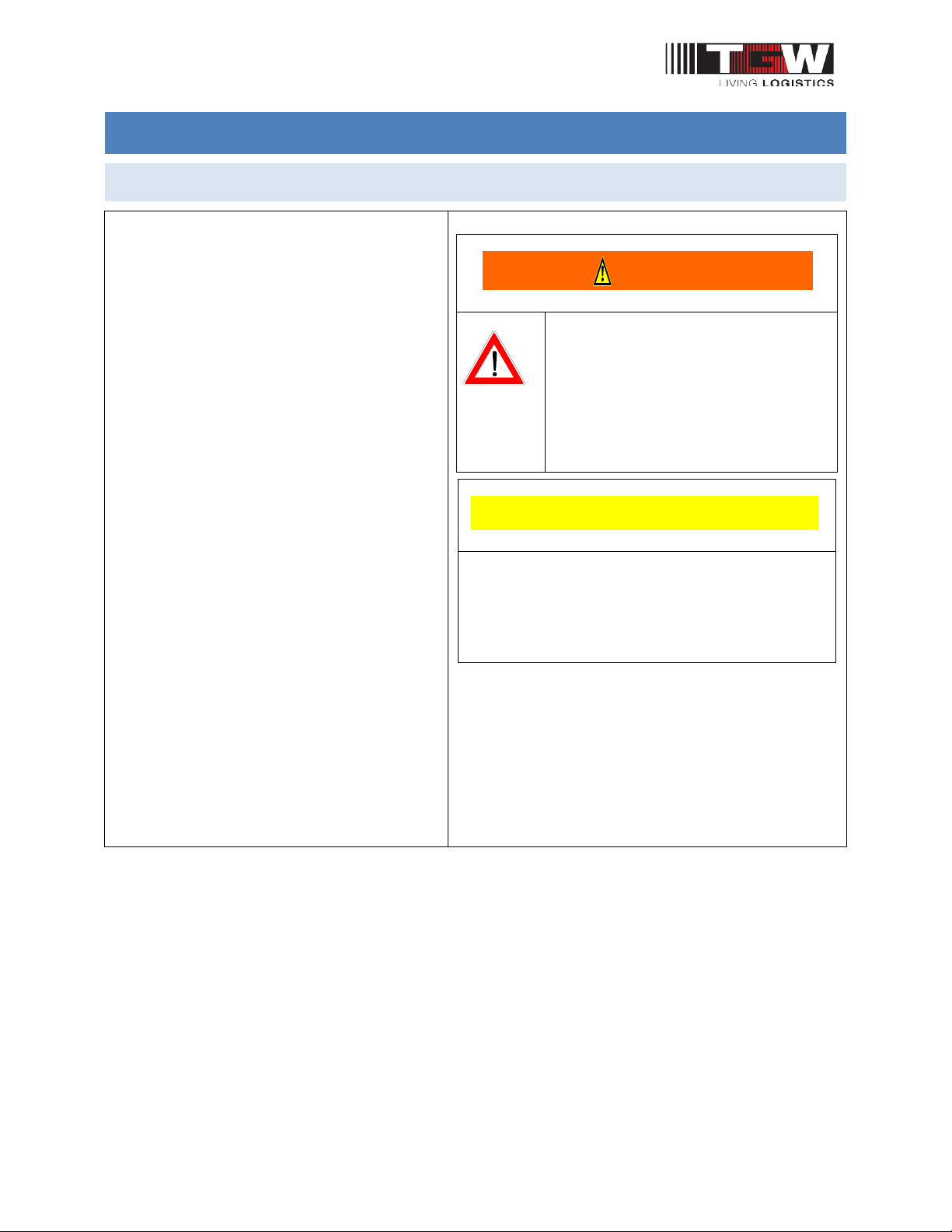
NBC CONVEYOR PREPARATION
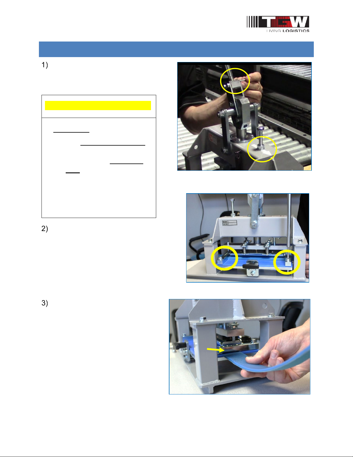
Make sure the main air regulator is at 40psi.
Before installing the belt, make sure the
air is OFF to the belt take-up. This
moves the take-up pulley to the
retracted position which allows you to
work with the maximum belt slack.
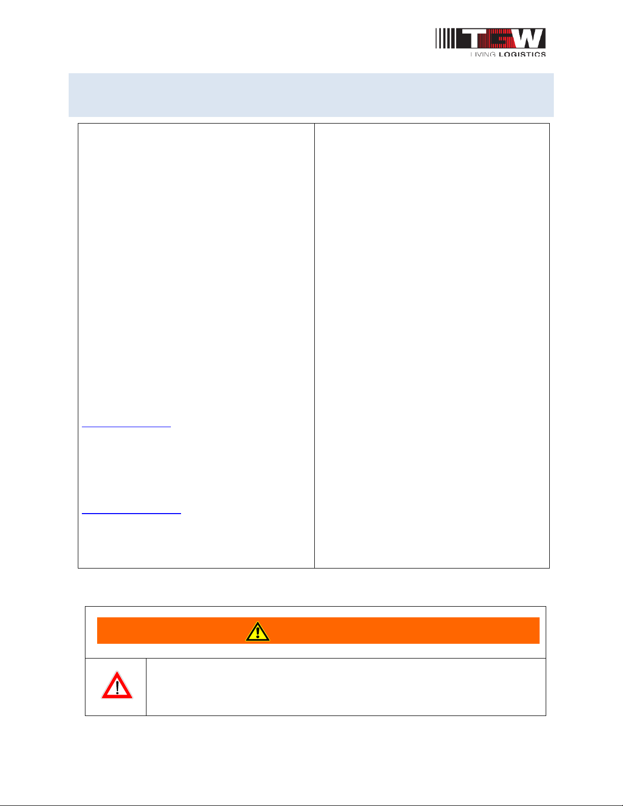
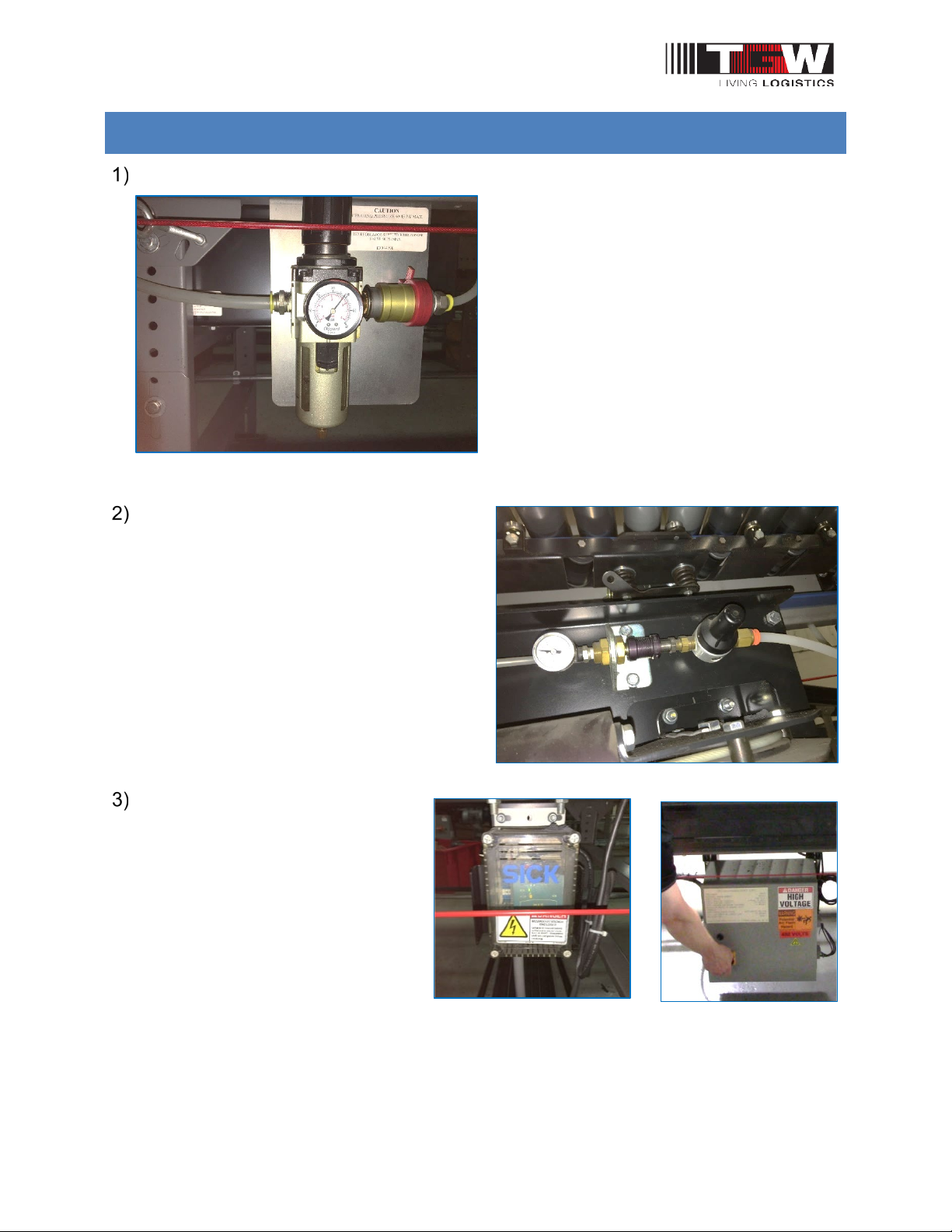
Turn off the power to the logic
modules.
Note: If you can’t find the power
supply, you can disconnect the
main power to the logic modules.
This will allow air to flow through
to the pressure pans and push the
pressure pans down.
TGW
P/N 1207439 Rev Date 09/13/2019 Page 8of 30
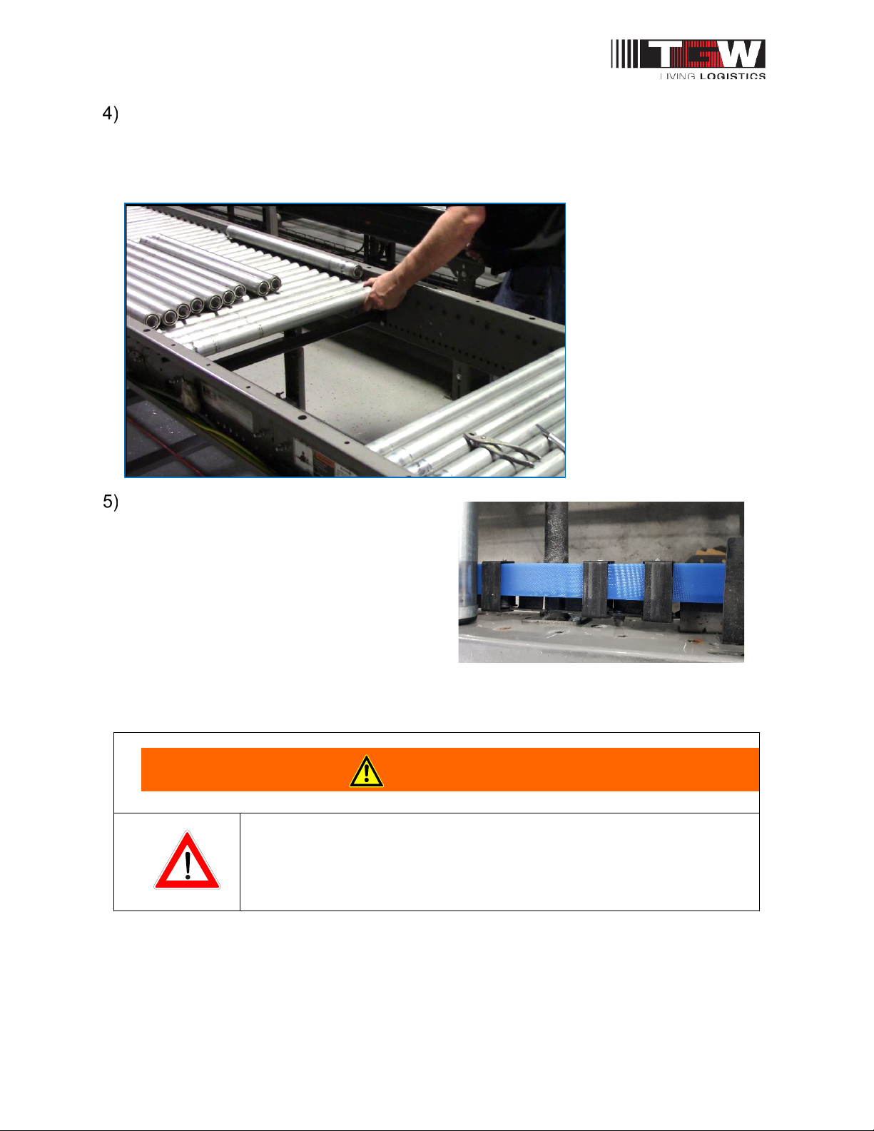
Remove rollers between two pressure pan supports in a 3' zone. Any zone can be
selected, but it is easier to select one near the charge or discharge end of the
conveyor.
Note:Pull the axles with pliers to protect the frame.
Remove any figure guards.
Depending on your work zone area, there
may be three (3) different finger guards.
Those between the pressure lift
assemblies simply snap-in or out. Those
over the pressure assemblies are
removed by rotating a quarter turn
clockwise and pulling out. If the belt
splicing work area includes in crossmember, a different shape finger guard is used,
which also snaps into place.
•Pay attention to the safety instructions!
•After maintenance, REPLACE guards immediately!
WARNING
TGW
P/N 1207439 Rev Date 09/13/2019 Page 9of 30
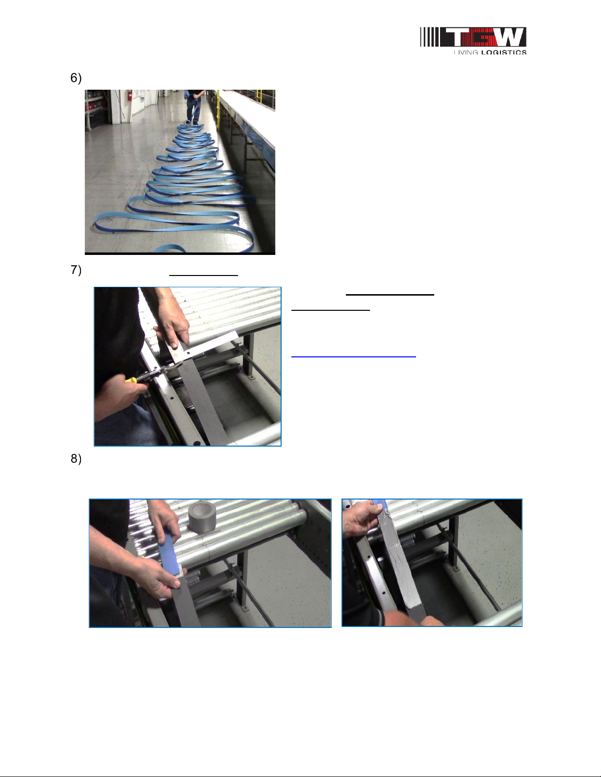
Un-coil the Nitta belt.
If replacing an existing belt, cut the previous belt straight.
Note: For new installation use the NBC
threading tool (located and attached under
each drive from factory). NBC threading
instructions are also in TGW IOM Manual at
www.tgw-conveyor.com.
Duct tape the top and bottom of the old belt end to the new Nitta belt end (thick
polyurethane side up) making sure to keep both belts are flat and straight, do not
overlap the belts.

TGW
P/N 1207439 Rev Date 09/13/2019 Page 10 of 30
Pull the new Nitta belt through the conveyor. Make sure the Nitta belt is routed
correctly over all the return pulleys underneath the conveyor. Remove the Duct
tape.
Before cutting the belt to length, make sure there is 18” overlap for NBC 150-AT
and for NBC 500-AT 36” overlap. The overlap is to compensate for belt loss in the
finger splice process. Both belt ends must be cut straight.
TGW
P/N 1207439 Rev Date 09/13/2019 Page 11 of 30
FINGER PUNCH PROCESS
Using the Nitta Finger Punch Press
assemble the handle and place the
press with the arrow sticker pointing in
the belt flow direction.
Loosen the bolts to the hold-down plates.
Insert one end of the belt,
polyurethane side up, through the
notched guide on the hold-down
bar. Slide the belt all the way
through to the other end of the
press.
WARNING:
•Use Only TGW Nitta belt
welder and punch
equipment for TGW Nitta
belt splice/welding. Non-
TGW Nitta belt welding or
punch equipment is not
compatible with the TGW
Nitta belt!
CAUTION

TGW
P/N 1207439 Rev Date 09/13/2019 Page 12 of 30
Hold the belt firmly while tightening the
hold-down bars bolts in an alternating
pattern.
Position the top index pin with the first
outside hole on the hold-down plate.
WARNING: Each hole must be punched in PROPER SEQUENCE and
in EVERY HOLE (6x). Failure to do so will cut off one of the fingers
making the belt unsliceable.
Starting at one end of the puncher,
make sure the top pin is aligned with
outside hole. Press the handle all the
way down. This is the 1st punch of 6
needed for each belt end.
Index pin
Hold-down holes (6X)
Move plate to align top index pin with the
first hole

TGW
P/N 1207439 Rev Date 09/13/2019 Page 13 of 30
Return the handle to original position. Move the support plate to the next hole and
repeat the process. When complete, loosen the hold-downs and remove the belt.
Repeat process for other belt end.
Thread the belt into the puncher from the
opposite direction.
WARNING: DO NOT ROTATE THE
FINGER PUNCH PRESS! The press
must stay in the same orientation for
the entire process.
Trim about 0.25”off each fingertip. This will
mate each finger in the pre-setter and to
ensure a good splice.
Handle to slide the support plate
Belt inserted from the left
Belt inserted from the right
TGW
P/N 1207439 Rev Date 09/13/2019 Page 14 of 30
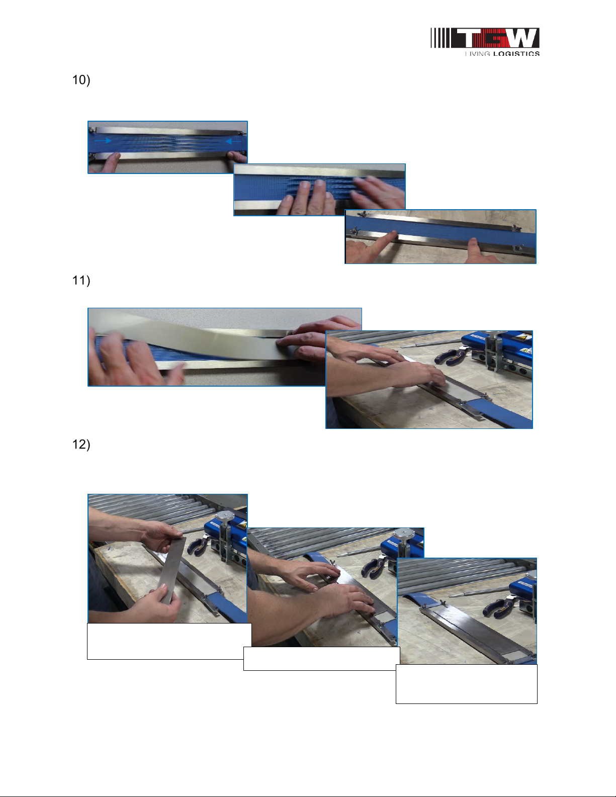
Install one end of the belt in the Pre-setter mold, making sure the belt fingers are
centered in the pre-setter plate. Insert the other end of the belt and slide the fingers
together, mating them with no overlaps or large gaps.
Install the silicone sheet, with textured side facing down on the belt finger spliced
section.
Place the pre-setter top plate center over the finger spliced area. Once the top plate
is centered, tighten the keeper plate wing nuts to keep the belt flat and secure.
Place pre-setter top plate
Center top plate
Tighten the keeper plate
wing nuts

TGW
P/N 1207439 Rev Date 09/13/2019 Page 15 of 30
NBC WELD INSTRUCTIONS
Place the TGW welder press on the conveyor and set the pre-setter mold center in
the weld press. Clamp the press closed and turn the knob until it slips.
CAUTION: Be careful not to pull out the belt from the pre-setter as this may cause
the finger splice to gap or overlap.
WARNING:
•Use Only TGW Nitta belt welder and punch equipment for TGW Nitta
belt splice/welding. Non-TGW Nitta belt welding or punch equipment is
not compatible with the TGW Nitta belt!
CAUTION
TGW
P/N 1207439 Rev Date 09/13/2019 Page 16 of 30
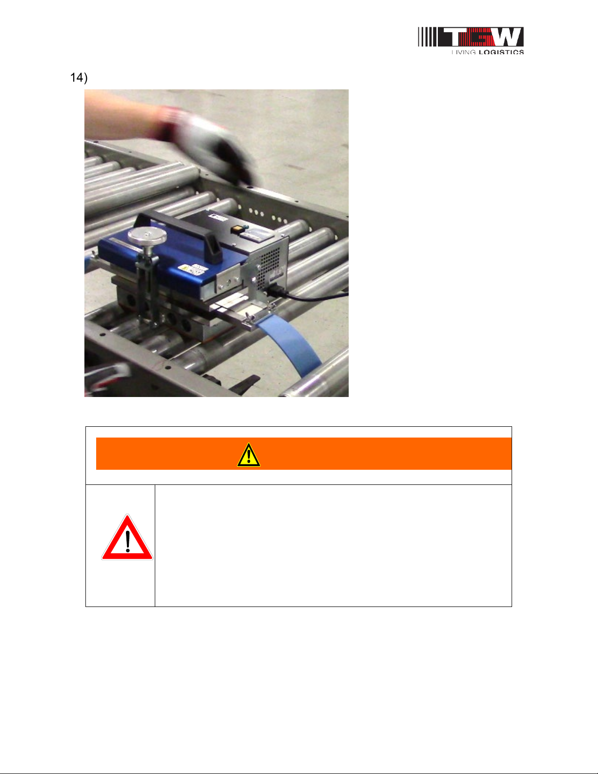
Plug in the TGW welder cord then push the yellow button to start.
WARNING! WELD PRESS IS HOT! TGW recommends to wear
heat resistant gloves when operating the press.
WELD PRESS IS HOT! Do not leave press unattended while in
use. To prevent others people from touching the weld press.
Failure to do so may cause others to touch the press and get
burned.
WARNING

TGW
P/N 1207439 Rev Date 09/13/2019 Page 17 of 30
Note: The green light is the actual temperature reading. The amber light is the welder
press pre-programmed temperature and should be set at 185 Degrees Celsius
(185°C).
Note: When starting the TGW welder press it will automatically run a diagnostic test
for about 6 seconds then starts heating up to the preset temperature. After 10
minutes at full temperature, the press will automatically shut down the heaters and
start the cooling fans. (Total weld time is approximately 60 minutes).
Note: The weld cool down process is
done when the actual temperature
gage (green light) is 50°C or lower.
WARNING:Before opening the
weld press remove the power
cord to ensure the power is off.
WELDER IS HOT! TGW
recommends wearing heat
resistant gloves!
GREEN LIGHT IS THE
ACTUAL TEMPERATURE
AMBER LIGHT IS
PRE-SET TEMPERATURE
AT (185°C)
50°C or BELOW
REMOVE WELDER POWER CORD!

TGW
P/N 1207439 Rev Date 09/13/2019 Page 18 of 30
Only when the actual temperature (green light) is 50°C or lower and when the
welder press power cord is unplugged it’s safe to open the TGW welder press.
Loosen the knob and pull the clamp down to open the press.
•WARNING! WELD PRESS IS HOT! TGW recommends to
wearing heat resistant gloves when operating the press.
•WELD PRESS IS HOT! Do not leave press unattended while in
use. Failure to do so may cause others to touch the press and
get burned.
WARNING

TGW
P/N 1207439 Rev Date 09/13/2019 Page 19 of 30
Remove the pre-setting mold, pre-setter top plate, silicone sheet, and loosen the
keeper plate wing nuts to unlock the belt. Remove the belt from the pre-setter mold.

TGW
P/N 1207439 Rev Date 09/13/2019 Page 20 of 30
Inspect the top and bottom of the belt. Make sure the belt splice has smoothly
joined even fingers with no bubbles, gaps, or overlaps. (See troubling shooting
section for defect details.)
TOP OF BELT (WELDED)
BOTTOM OF BELT
(WELDED)
Other manuals for NBC
1
Table of contents
Popular Welding Accessories manuals by other brands

Lincoln Electric
Lincoln Electric LN-7 Operator's manual

Lincoln Electric
Lincoln Electric AutoDrive 4R90 Brochure & specs

ThermOweld
ThermOweld CRE-1 instructions

AMERICAN WELDQUIP
AMERICAN WELDQUIP 550A manual

Scheppach
Scheppach AWH-500FL Translation of original instruction manual

ESAB
ESAB PSF 250 instruction manual

ewo
ewo 913 ASD operating instructions

Rohrman Schweißtechnik
Rohrman Schweißtechnik XA-5001 Pro instruction manual

Trafimet
Trafimet ADAPTIG G9 Operating and maintenance manual

EWM
EWM TIG 17 G operating instructions

GYS
GYS 038424 manual

Lincoln Electric
Lincoln Electric Metalshield MC-715 Specification sheet


