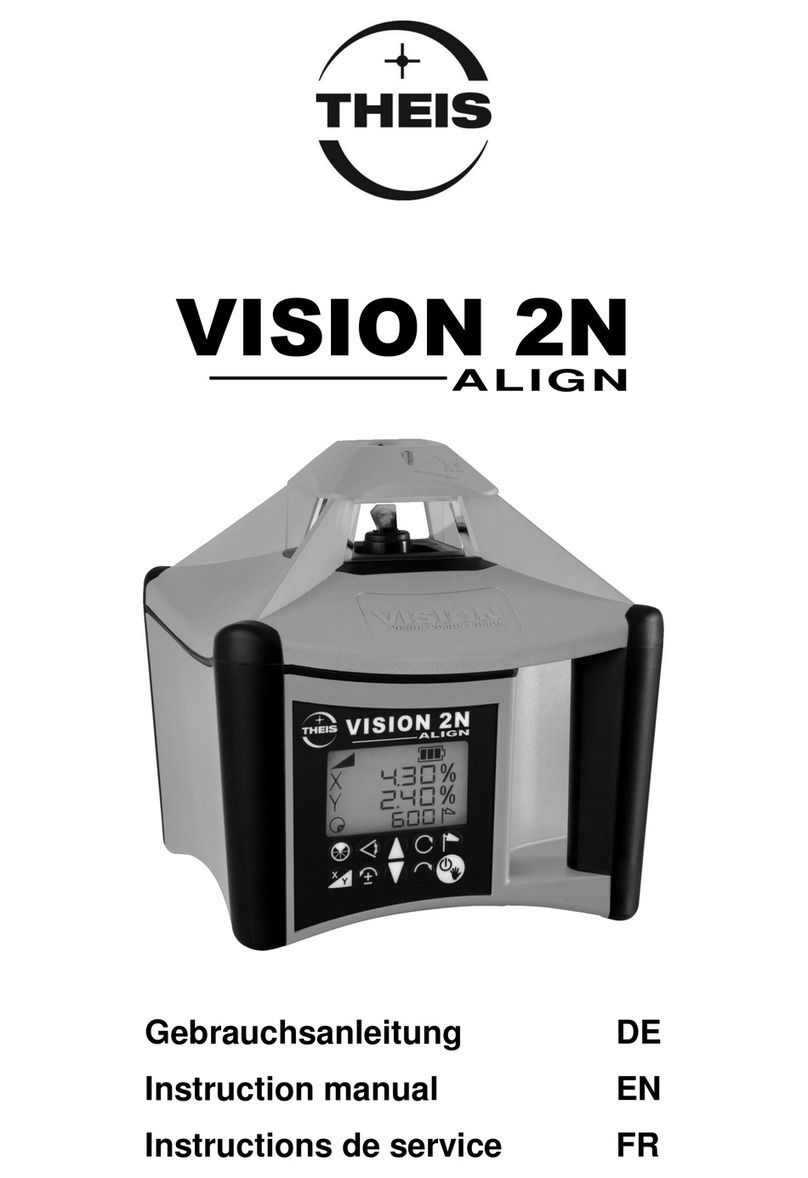
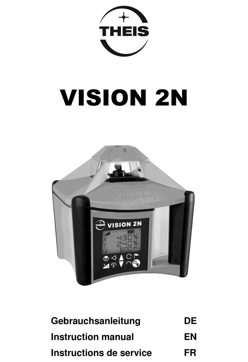
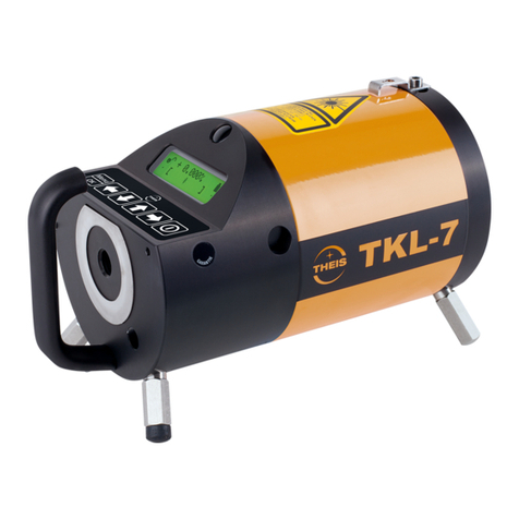
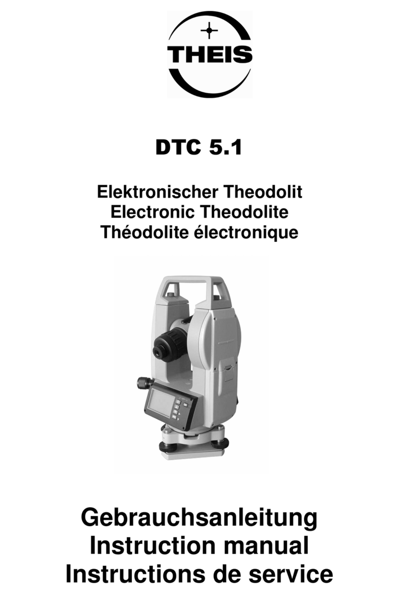
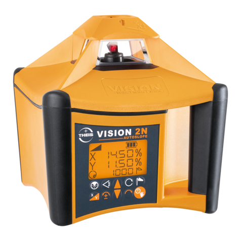
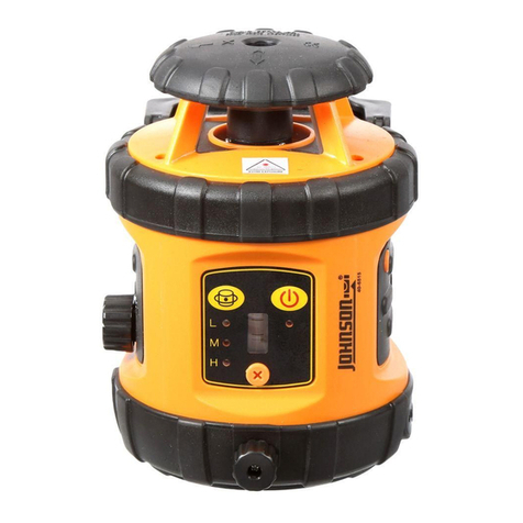
THEIS Quickset User manual

Gebrauchsanleitung
(D)
I
nstruction manual (UK)
Instructions de service
(F)
QUICKSET
Gebrauchsanleitung
D
Vorwort
Der Quickset ist das Einsteigermodell in der Klasse der
vollautomatischen Rotationslaser mit sichtb
arem Strahl für alle
horizontalen Anwendungen. Dabei wurden keine Kompromisse
hinsichtlich Genauigkeit und Leistung eingegangen.
Sein funktionelles Bedienfeld garantiert einfachste Handhabung
für viele Messaufgaben im Innen
-
und Außenbereich.
Alle Instru
mente werden vor Auslieferung sorgfältig geprüft.
Damit Sie stets ein einsatzbereites Gerät haben, sollten
folgende Hinweise beachtet werden:
1.
Das Gerät
niemals nass
im Behälter aufbewahren.
2.
Genauigkeit vor jedem Einsatz überprüfen, da wir keine
Haftung f
ür Dejustierung übernehmen können.
3.
Hinweise zur Behandlung des Akkus beachten.
Laser
-
Austritt
-
Fenster und Sensor
-
Fenster des Empfängers
(Option) schonend behandeln.
1
1.
Bedienungselemente / Anzeige
(1)
Laseraustritt
(2)
Horizontierungsa
nzeige
(3)
Betriebsanzeige
(4)
Ein/Aus
-
Schalter
(5)
Akku
kontroll
a
nzeige
(6)
Akkufach mit Ladebuchse rückseitig
2
(4)
(5)
(6)
(3)
(2)
(1)

2. Vorbereitung zur Messung
Quickset auf einen stabilen, flachen Untergrund aufstellen oder auf ein
Stativ
fest
aufschrauben.
Stativ im Bereich
5
° ausrichten und Laser
n
ivellier mit
Taste (4)
einschalten. Die Betriebsanzeige (3) leuchtet auf und
die
Horizontierungs
anzeige
(2)
blinkt
.
Falls der Stativkopf stärker als 5° geneigt war, wird dies nach kurzer Zeit durch
schnelles
Blinken des Laserstrahl
s und de
r
Horizontierungsanzeige
(
2
) angezeigt.
In diesem Fall Gerät ausschalten und Stativ sorgfältiger ausrichten.
Nachdem der Horizontier
v
organg beendet ist, beginnt der Laserstrahl zu rotieren
und die Horizontierungsanzeige (2) erlischt
.
3
.
TILT Fu
nktion
Eine so genannte
Tilt
-
Funktion
sorgt generell dafür, dass sich bei größeren
Veränderungen in der Höhe (z.B. versehentliches Verstellen eines Stativbeins)
das Gerät abschaltet und dies durch
schnelles
Blinken des Laserstrahls und der
Horizontierungs
anzeige (
2
) meldet.
Anschließend muss das Gerät neu ausgerichtet und gestartet werden.
4
. Stromversorgung
4.1 Laser
Sobald
die
Akkukontrollanzeige (5)
blinkt ist die Kapazität
des Akkus
erschöpft
und der Akku muss dringend geladen werden. Wird
dies nicht beachtet
,
schaltet
das Gerät nach kurzer Zeit automatisch ab.
Nachladen des Akkus nur mit
THEIS
Standard
-
Lade
gerät über Ladebuc
h
se
(6)
am Akkufach des Lasernivelliers
.
Der Akku kann auch geladen werden, wenn
das Akkufach vom Laser getrennt is
t.
Ein Überladen ist nicht möglich
, sofern nicht mehrfach hintereinander geladen
wird.
Ein Überladen verkürzt die Lebensdauer des Akkus.
Der Akku soll bei Raumtemperatur geladen werden. Das Laden
unter +5°C kann
zu einem Defekt des Akkus führen.
Ladegerät nur in trockenen Räumen einsetzen!
Auch bei Nichtbenutzung des Gerätes Akku spätestens
alle
6 Wochen aufladen!!!
4.2 Empfänger
Wenn Batteriesymbol
(18)
in der LCD
-
Anzeige erscheint, sollte die Batterie
(9 V, E
-
Bl
ock) gewechselt werden, da sonst die Reichweite eingeschränkt sein
kann.
Schiebedeckel des Batteriefaches leicht eindrücken und seitlich aufschieben.
Alte Batterien sachgemäß entsorgen und bei neuer Batterie auf richtige Polung
achten
(siehe Symbole).
3 4
5
. Empfänger
Empfänger durch Drücken der Taste (12) einschalten und gewünschte Funktion
vorwählen: Fein- oder Grobeinstellung (11) (Grundeinstellung TE 4/5 ist Grob)
und akustisches Signal (7). Gewählte Funktion erscheint in der LCD-Anzeige (10).
Darüber hinaus informiert die Anzeige beim Vermessen darüber, in welche
Richtung der Empfänger bewegt werden muss (Pfeile) (16).
Sensorfenster (8) zum Quickset
hinwenden und auf und ab durch den rotierenden
Laserstrahl fahren, bis in der LCD (10) eine
Anzeige erfolgt. Den Empfänger dann
solange zum Zentrum bewegen, bis ständig nur der Zentrums-Balken (17)
angezeigt wird.
Bei eingeschaltetem Horn (7) ertönt bei Balkenanzeige ein Dauerton. Bei
Pfeilanzeige (16) erkennt man an einem unterschiedlich pulsierenden Ton, ob der
Empfänger zu hoch oder zu tief gehalten wird.
Die Einstellung der Lautstärke des Horns erfolgt beim TE 5 in zwei Stufen.
Trifft ca. 7 Minuten lang kein Laserstrahl auf das Empfangsfeld (8)
(Sensorfenster), schaltet der Empfänger ab.
Bedienelemente für TE 4, TE 5:
(7)
Taste / Anzeige: Horn
(8)
Sensorfenster
(9
) Kerbe Zentrum
(
10
) LCD
-
Anzeige (auch auf Rückseite)
(
11
) Taste Fein / Grob
(
12
) Taste Ein / Aus
(
13
) Austritt akustisches Signal (Horn)
(
14
) Anzeige Fein
(
15
) Anzeige Gr
ob
(
16
) Pfeile für Bewegungsrichtung
(
17
) Zentrum / Balken
(
18
) Batteriekontroll
a
nzeige
(
19
) Anzeige Ein
(
20
) Batteriefach
TE
4
5 6
(10)
(7)
(18)
(15)
(16)
(14)
(17)
(16)
(7)
(11)
(12)
(13)
(9)
(8)

TE
5
6
. Überprüfung
der Justierung
Laser
n
ivellier wie unter
2
. beschrieben, allerdings auf einem
sehr gut
ausgericht
e
ten Stativ
,
aufbauen und entlang einer etwa 30 m langen
Messstrecke
-
beispielsweise in X
-
Achse
-
ausrichten und einschalten.
Am Ende der Messstrecke in Hö
he des Laserstrahls eine Markierung vornehmen.
Anschließend Laser
-
Gerät um 180° drehen und erneut eine Markierung setzen.
Danach die gleichen Prüfungen auch in der Y
-
Achse vornehmen. Falls alle
Markierungen übereinander liegen oder nur unwesentlich (max.
3
mm)
voneinander abweichen, ist die Justierung in Ordnung. Falls größere
Abweichungen vorliegen, muss das Gerät von einem Fachbetrieb übe
r
prüft und
neu kalibriert werden.
7
. Lieferantenerklärung/Sicherheitshinweise
Das Gerät stimmt mit den europäischen
Richtlinien 89/336/EWG
Elektromagnetische Verträglichkeit und 73/23/EWG Elektrische Betriebsmittel
zur Verwendung innerhalb bestimmter Spannungsgrenzen
(Niederspannungsrichtlinie) überein.
Zur Beurteilung wurden die harmonisierten Normen EN 61326, EN 55022
,
EN 61000
-4-
2, 61000
-4-
3 und EN 60825
-
1 verwendet.
Sicherheits
-
Hinweisschild befindet sich auf de
m
Gehäuse
des Gerätes
.
Eingebaut ist ein gekapselter Laser Klasse 3R.
Beim Öffnen des Gerätes
besteht deshalb die Mögl
ichkeit, in den Bereich höherer Leistungswerte
als der Klasse 2
zu gelangen. Laser nach Möglichkeit nicht auf Personen
ausrichten. Nicht in den Laserstrahl blicken, auch nicht mit optischen
Instrumenten.
Keine zu wartenden oder justierenden Teile im Innere
n des Gerätes.
Service darf nur von autorisierten Stellen ausgeführt werden.
7 8
8
. Garantie
Wir gewährleisten für unsere Erzeugnisse eine dem heutigen Stand der Technik
entsprechende Fehlerfreiheit in Material und Werkarbeit. Sollten sich derart
ige
Mängel beim praktischen Gebrauch zeigen, so werden diese kostenlos behoben.
Die Garantiezeit beträgt
24
Monate ab dem Verkaufsdatum (Rechnungsdatum).
Für die Reparatur oder Umtausch sind Gerät und/oder betroffene Teile
unverzüglich nach Feststellung de
s Mangels an THEIS zu senden.
Keine Garantieansprüche bestehen auf kostenlose Behebung von Fehlern, die
durch unsachgemäße Behandlung oder Aufbewahrung entstanden sind sowie
jegliche Schadensersatzansprüche, insbesondere auch solche auf mittelbare
Schäden
. Ferner erlischt jeder Garantieanspruch, wenn technische Eingriffe von
fremder Seite
–
also nicht durch die Firma THEIS
–
vorgenommen werden.
9
. Entsorgung
Elektrowerkzeug, Zubehör und Verpackung sollten einer umweltgerechten
Wiederverwertung zugeführt werden.
Nur für EU-Länder:
Werfen Sie Elektrowerkzeuge nicht in den Hausmüll!
Gemäß der Europäischen Richtlinie 2002/96/EG über Elektro-
und Elektronik - Altgeräte und ihrer Umsetzung in nationales
Recht müssen nicht mehr gebrauchsfähige Messwerkzeuge
getrennt gesammelt und einer umweltgerechten
Wiederverwertung zugeführt werden.
Batterien/Akkus:
Werfen Sie Batterien und Akkus nicht in den Hausmüll, ins Feuer oder ins
Wasser. Batterien und Akkus sollen gesammelt, recycelt oder auf
umweltfreundliche Weise entsorgt werden.
Nur für EU-Länder:
Gemäß der Richtlinie 91/157/EWG müssen defekte oder verbrauchte Batterien
und Akkus recycelt werden.
Nicht mehr gebrauchsfähige THEIS Lasergeräte und Akkupacks können direkt
abgegeben werden bei:
THEIS FEINWERKTECHNIK GMBH
Zum Bolzenbach 26
35236 Breidenbach
Telefon
06465/67
-0
Fax
06465/67
-
25
Email
info@theis
-
feinwerktechnik.de
10. Technische Daten
Laser
n
ivellier
Laserklasse
2
Betriebsdauer
˜
20
h
Ausgangsleistung
max. 1mW
Stromversorgung
NiMH
4,8
V
; 2,1
Ah
Wellenläng
e
635nm
Ladezeit
˜
5h
Selbstnivellierbereich
±4°
Arbeitstemperatur
-
10 bis +
5
0°C
Genauigkeit
±1
mm/
1
0m
Schutzart
IP 6
5
Drehzahl
650
U/min
Gewicht
˜1
kg
Empfänger (Option)
TE 4
TE 5
Empfangsfeld
50 mm
70
mm
Reichweite
150 m
300 m
Genauigkeit
-
fein
±2
mm
±
2 mm
Genauigkeit
-
grob
±
3 mm
±
4 mm
Betriebsdauer
˜
50
h
˜8
0 h
Stromversorgung
9 V, E
-
Block
Betriebstemperatur
-
10 bis +
50 °C
Schutzart
IP 65
IP 67
Größ
e
135x65x24mm
155x75x27mm
Gewicht
˜
200 g
˜
250 g
11
1
. Zubehör
Standard:
Optionen:
Ladege
rät
Empfänger TE 5 mit
Gebrauchsanleitung
Befestigungsklammer
Empfänger TE 4 mit
Zieltafel
Befestigungsklammer
9
10
(13)
(12)
(7)
(18)
(15)
(16)
(14)
(17)
(16)
(10)
(9)
(7)
(8)
(11)
(20)

Operating Instructions
UK
Introduction
The Quicks
et is the beginner model in the class of fully
automatic rotation lasers with visible beam for all horizontal
applications. The instrument makes no compromise with
respect to accuracy and performance.
Its functional control panel guarantees easy handling
for various
measuring tasks at indoor and outdoor applications.
Prior to shipment all instruments are carefully checked.
Read the complete Operating Instructions including the
Technical Data and the Safety Requirements prior to using the
equipment the fi
rst time.
We recommend you to observe the following items so that your
laser is ready for use at all times:
1.
Never
place the instrument in its case when
wet
.
2.
Check the accuracy each time before using the instrument,
as we cannot assume any responsibility
for adjustment
errors.
3.
Follow the instructions for handling the accu.
4. Treat the laser beam window and sensor window of the
receiver (option) with
care.
1.
Operating elements /
Display
(1)
Laser exit
(2)
Out of level indicator
(3)
O
peration indicator
(4)
Button On/Off
(5)
Accu condition indicator
(6)
Accu compartment with charging socket on the back
11
12
2.
Preparations for measurement
Set up the Quickset on a solid, even ground or screw it on tight on a tripod.
Align the tripod wit
hin the range of < 5° and
p
ress key (
4
) to activate the
instrument.
The
operating indicator (3) lights up and the out of level indicator (2)
is blinking.
If the tripod head was tilted more than 5°, this will be indicated after a brief period
of time by
rap
id
flashing of the laser beam and the
out of level indicator
(
2
).
Should this occur, shut off the instrument and align the tripod more carefully.
As soon as the laser levelling process has been finished, the laser beam starts
rotating
and the out of leve
l indicator expires.
3
.
TILT function
Should major height changes occur (e.g. an inadvertent jerk of the tripod leg), a so
called
Tilt function
effects a shutdown of the laser beam even within the
automatic levelling range, and this occurrence is signa
lled by rapid flashing of the
laser beam and the
out of level indicator
(
2
).
The instrument has to be readjusted and switched on.
4. Power supply
4.1 Laser
As soon as the
accu condition indicator
(5)
blinks, the capacity of the
accumulator is exh
austed and the accu has to be recharged immediately. If the
indicator is ignored, t
he instrument switches off automatically a short time later.
Recharging of the accumulator only with THEIS standard
-
charger via charging
socket (6) at the accu compartment
of the laser level. The accu can also be
charged, if the accu compartment is
separated
from the laser level.
Overloading is not possible
, if charging is not repeated
successive
several times.
If possible the accu should be charged
at
room temperature. Char
ging under
+5°C can cause the damage of the accu.
Never operate charger in damp rooms!
Please charge the instrument at least every 6 weeks, even it is not
used!!!
4.2 Receiver
When the battery symbol (18) appears on the LCD-display, change the battery
(9V, E-Block), otherwise the range may be reduced.
Press sliding cover of battery section slightly, then push it sideways open.
Dispose old batteries properly. Watch for the right polarity when inserting the
new batteries. (Pay attention to symbols at the receiver case)
13
14
(3)
(2)
(4)
(5)
(6)
(1)

5. Receiver
Turn on the receiver by pushing the On/Off button (12) and select requested
function: Fine (14) or coarse (15) setting with button (11) (basic setting for TE 4/5
is coarse) and acoustic signal with button (7). Selected function is shown on the
LCD display (10). In addition to this, the arrow symbols (16) on the display inform,
in which direction the receiver has to be moved, while measuring.
Turn the sensor window (8) into the direction of the Quickset and move up and
down through the rotating laser beam, until the LCD display shows the arrow
symbols. Move the receiver in the direction of the arrow and stop, when the center
bar (17) is shown constantly.
If the buzzer (7) is activated, there will be a permanent sound, when the center
bar is shown. When the arrows (16) are displayed, there will be a pulsating sound,
which will be different, dependent on the position of the receiver over or under the
center hight.
TE 5 has two different settings for the sound intensity of the buzzer.
If the laser beam does not hit the beam receiving window (8) for more then 7
minutes, the receiver will turn off.
Operating elements for TE 4, TE 5:
(
7
)
Button / Figure:
Buzzer
(
8
)
B
eam receiving window
(
9
)
Center notch
(1
0
)
LCD
-
Display (front and rear)
(11) Button Fine/Coarse
(1
2
)
Button On/Off
(1
3
)
Holes for Buzzer
(
14
)
Figure Fine
(
15
)
Figure Rough
(
16
)
Arrows for
moving direction
(
17
)
C
enter bar
(
18
)
B
attery indicator
(
19
) Figu
re On
(2
0
) Battery case
TE
4
15
16
TE
5
6
. Calibration check
Set up levelling instrument as described in section 2. onto an extremely well
levelled tripod, and along a measurin
g range of approx. 30 metres
–
for example
in the X
-
axis direction
–
level and turn on.
Place a mark at the end of the measuring range at the height of the laser beam.
Subsequently, turn the laser 180° and place a second mark. Afterwards, carry out
the sam
e test along the Y
-
axis If all marks are at equal height or hardly deviate
(max.
3
mm), the calibration is correct. If larger deviations are found, the unit must
be re
-
calibrated by an authorised workshop.
7
. Supplier’s / Safety information
The unit is d
esigned in accordance with European Standards 89/336/EEC
Electromagnetic Compatibility and 73/23/EEC Electric Equipment for use within
certain voltage limits (Low
-
voltage Directive).
For evaluation purposes, the harmonised Standards EN
61326,
EN
55022,
EN
61000
-4-
2, EN 610
00-4-3
and EN 60825
-
1 have been applied.
Safety information label is placed on the
case
of the instrument.
A Class 3
R
embedded laser has been installed. On opening the unit, one
must be aware of t
he fact that higher energy levels than Class 2 are present.
Avoid pointing the laser in the direction of persons. Do not look into the
laser beam.
There are no parts requiring adjustment or maintenance inside the unit.
Service operations may only be carrie
d out by authorised workshops.
17
18
(10)
(7)
(18)
(15)
(16)
(14)
(17)
(16)
(7)
(11)
(12)
(13)
(9)
(8)
(13)
(12)
(7)
(18)
(15)
(16)
(14)
(17)
(16)
(10)
(9)
(7)
(8)
(11)
(20)

8
. Guarantee
We guarantee our products to be faultless in material and workmanship in
keeping with modern engineering standards. Any such faults that may appear in
practical use will be remedied free of ch
arge. The period of warranty is 24 month
from the date of sale (date of invoice). For repair or exchange the instrument
and/or the requested parts have to be sent immediately
,
after detection of the
fault
,
to THEIS.
Outside the guarantee are: Claims for c
ost
-
free remedying of faults arising from
improper handling or storage; also all claims for damages, in particular those for
consequential damages. Moreover all guarantee claims lapse if outside technical
intervention
–
i.e. not by THEIS is undertaken
.
9.
Disposal
The measuring tool, accessories and packaging should be sorted for
environmental
-
friendly recycling.
Only for EC countries:
Do not dispose of measuring tools into household waste!
According to the European Directive 2002/96/EG on waste
elect
rical and electronic equipment and its incorporation into
national law, measuring tools that are no longer suitable for use
must be separately collected and sent for recovery in an
environmental
-
friendly
recycling
.
Batteries/Accumulators
:
Do not dispose
of
accumulators and batteries
into household waste, fire or water.
Accumulators and batteries
should
be collected, recycled or disposed of in an
environmental
-
friendly manner.
Only for EC countries:
Defective or dead out
batteries and accumulators
must be
recycled according
the guideline 91/157/EEC.
THEIS Laser
-
instruments and accu
-
packs
no longer suitable for use can be
directly returned
to
:
THEIS FEINWERKTECHNIK GMBH
Zum Bolzenbach 26
35236 Breidenbach
Phone
06465/67
-0
Fax
06465/67
-
25
Email
info@thei
s-
feinwerktechnik.de
10. Technical data
Laser Level
Laser class
2
Running time
˜
20
h
Output power
max. 1mW
Power supply
NiMH
4,8
V;
2,1
Ah
Wavelength
635nm
Charging time
˜
5h
Auto levelling range
±
4°
Oper
ating temp.
-
10 till +50°C
Accuracy
±
1mm/
10m
Type of protection IP 65
Speed
65
0 rpm
Weight
˜
1kg
Receiver (Option)
TE 4
TE 5
Detective
area
50 mm
70 mm
Range (radius)
150 m
300 m
Accuracy
-
fine
±
2 mm
±
2 mm
Accuracy
-
rough
±
3 mm
±
4 mm
Running ti
me
˜50
h
˜8
0 h
Power supply
9 V, E
-
battery
Operating temp.
-
10
till
+50 °C
Type of protection
IP 65
IP 67
Dimensions
135x65x24mm
155x75x27mm
Weight
˜
200 g
˜
250 g
111.
Accessories
Standard:
Options:
Charger
Detector
TE 5 with
Operating instructi
ons
Fixing clamp
Detector TE 4 with fixing clamp
Target
19
20
Instructions de service
F
Avant
-
propos
Le Quickset est le modèle de base de la classe des appareils
laser rotatifs à rayons visibles totalement automa
tiques pour les
applications horizontales. Aucun compromis n’a été fait en
matière de précision et de performances.
Son champ de commande fonctionnel garantit une manipulation
des plus aisées pour de nombreuses applications de mesure,
tant à l’intérieur qu’à l’extérieur.
Tous les instruments sont minutieusement contrôlés avant leur
livraison.
Pour assurer durablement le bon fonctionnement de votre
appareil, nous vous prions de lire attentivement les instructions
suivantes
:
4.
Ne
jamais
ranger un appareil dans son coffret lorsqu'il est
mouillé.
5.
Vérifier la précision avant chaque utilisation
; nous déclinons
toute responsabilité en cas de déréglage de l'appareil.
6.
Tenir compte des instructions concernant le traitement de
l'accu.
4.
La fenêtre de sortie du r
ayon laser ainsi que la fenêtre de
la sonde du récepteur (option) sont à manipuler avec le
plus grand soin.
1. Eléments de commande / Affichage
(1)
Sortie du rayon laser
(2)
Indicateur d’horizontalité
(3)
Témoin de fonctionnement
(4)
Interrupteur Marche/Arrêt
(5)
Témoin de contrôle de l’accu
(6)
Compartiment de l’accu, avec prise de chargement à l’arrière
21
22
(4)
(5)
(6)
(3)
(2)
(1)

2. Préparatifs de mesure
Placer le Quickset sur une surface plane et stable ou le visser sur un trépied.
Ajuster le trépied dans une plage < 5° et allumer le niveau laser avec la touche
(4).
Le témoin de fonctionnement (3) s’allume et l’indicateur d’horizontalité (2)
clignote.
Une inclinaison de la tête du trépied supérieure à 5° est signalée après un court
instant p
ar un clignotement
rapide
du rayon laser et de l’indicateur d’horizontalité
(2). Dans ce cas, éteindre l’appareil et ajuster soigneusement le
trépied.
Lorsque l'opération de mise à l'horizontale est terminée, le rayon laser se met à
tourner et l’indicate
ur d’horizontalité (2) s’éteint.
3. Fonction TILT
Dans le cas de modifications importantes sur la hauteur (occasionnées p. ex. par
le déplacement involontaire d'une jambe du trépied), la
fonction Tilt
assure la
mise hors circuit de l'appareil et avertit
par un clignotement
rapide
du rayon laser
et de l'indicateur d’horizontalité (2).
Il faut ensuite procéder au réajustement de l'appareil avant de le remettre en
marche.
4. Alimentation électrique
4.1 Laser
La capacité de l’accu est épuisée dès que le
témoin de contrôle de l’accu (5)
clignote
; l’accu doit alors être rechargé au plus vite. Si ce n’est pas le cas,
l’appareil s’arrête automatiquement après un court instant.
Seul le chargeur standard THEIS peut être utilisé pour recharger l’accu au moye
n
de la prise de chargement du compartiment de l’accu du niveau laser. L’accu peut
également être chargé lorsque
le compartiment de l’accu est démonté du laser.
Aucune surcharge n’est possible lorsque l'accu n'est pas chargé plusieurs fois
consécutivement.
La durée de vie de l’accu peut être réduite par les surcharges.
L’accu doit être chargé à température ambiante. Un chargement sous +5
°C peut
entraîner des dommages à l’accu.
Utiliser uniquement le chargeur dans des lo
caux parfaitement secs
!
Même si l’appareil n’est pas utilisé, l’accu doit être rechargé
au plus tard toutes les 6 semaines !!!
4.2 Récepteur
La batterie (9 V, bloc électrique) doit être remplacée lorsque le symbole de la
batterie (18) apparaît dans l’é
cran LCD
; dans le cas contraire, la portée de
l’appareil peut être limitée.
Appuyer légèrement sur le couvercle coulissant du compartiment de la batterie et
le déplacer latéralement.
Eliminer les anciennes batteries dans le respect des directives en vigu
eur et
respecter la polarité lors de la mise en place des nouvelles batteries
(voir symboles).
23
24
5. Récepteur
Allumer le récepteur en appuyant sur la touche (12) et sélectionner la fonction
souhaitée : Réglage fin ou grossier (11) (le réglage de base est « grossier » pour
TE 4/5)
et signal acoustique (7). La fonction choisie apparaît dans l’affichage LCD
(10).
Pendant la mesure, cet affichage indique également le sens dans lequel le
récepteur doit être déplacé (flèche) (16).
Tourner la fenêtre de la sonde (8) vers le Quickset
et la déplacer de haut en bas à
travers le rayon laser jusqu’à ce que l’affichage LCD (10) indique quelque chosE.
Déplacer alors le récepteur vers le centre jusqu’à ce que seule la barre centrale
(17) s’affiche en permanence.
Un signal continu retentit lorsque la barre s’affiche lorsque l’avertisseur sonore (7)
est allumé. L’affichage des flèches (16) est signalé par différentes tonalités
indiquant si le récepteur est placé trop haut ou trop bas.
Le réglage du volume de l’avertisseur sonore se fait sur deux niveaux pour
le TE 5.
Le récepteur s’éteint lorsqu’aucun rayon laser n’est émis pendant env.
7 minutes dans le champ de récepteur (8) (fenêtre de la sonde).
Eléments de commande pour TE 4, TE 5 :
(7)
Touche / Affichage
: Avertisseur sonore
(8)
Fenêtre de la sonde
(9)
Encoche au centre
(10)
Ecran LCD (également sur la face arrière)
(11)
Touche Fin / Grossier
(12)
Touche Marche / Arrêt
(13)
Sortie du signal sonore (avertisseur sonore)
(14)
Affichage Fin
(15)
Affichage Grossier
(16)
Flèche pour le sens de déplacement
(17)
Centre / Barre
(18)
Témoin de contrôle de la batterie
(19)
Affichage Marche
(20)
Compartiment à batterie
TE
4
25
26
(10)
(7)
(18)
(15)
(16)
(14)
(17)
(16)
(7)
(11)
(12)
(13)
(9)
(8)

TE
5
6. Vérification de l’ajustage
Installer le niveau laser conformément aux indications du paragraphe 2 en veillant
scrupuleusement au positionnement parfait du trépied. Ajuster le niveau laser sur
une distance d'environ 30 m
–
par exemp
le sur l'axe X
–
et le mettre en marche.
Effectuer un marquage à la fin de cette distance de mesure, à la hauteur du rayon
laser. Faire ensuite pivoter l'appareil laser de 180° et procéder à nouveau à un
marquage. Exécuter ensuite les mêmes opérations sur
l'axe Y. Si tous les
marquages se chevauchent ou s'ils ne divergent que d'une valeur négligeable (2
mm max.), cela signifie que l'ajustage est correct. Si les divergences sont plus
importantes, l'appareil doit être confié à une entreprise spécialisée qui
le
contrôlera et procèdera à son calibrage.
7. Déclaration du fournisseur / consignes de sécurité
Cet appareil est conforme aux prescriptions européennes 89/336/EWG
concernant la compatibilité électromagnétique et 73/23/EWG concernant
l'appareillage éle
ctrique destiné à être utilisé dans une plage de tensions
déterminée (directive de basse tension).
L'attestation se base sur les normes harmonisées EN 55011 classe B (EN 61000
-
6-
1), EN 61000
-6-
2, EN 61010
-
1 et EN 60825
-
1.
La plaquette portant les consigne
s de sécurité se trouve sur la face gauche de
l'appareil.
L'appareil est équipé d'un laser blindé de classe 3A. En ouvrant l'appareil, il
est donc possible d'accéder à une plage de valeurs de puissance
supérieures à cell
es de la classe 2. Eviter autant que possible d'orienter le
laser vers des personnes. Ne jamais regarder dans le rayon laser, même à
travers un instrument optique quelconque.
Aucune pièce nécessitant réglage ou entretien n'est intégrée à l'intérieur de
l'a
ppareil.
Seuls les services habilités compétents sont autorisés à pratiquer les
opérations de maintenance.
27
28
8. Garantie
Nous garantissons que les matériaux utilisés pour nos produits, ainsi que les
méthodes utilisées pour leur fabrication
sont exempts de tout défaut et
correspondent à l’état actuel des techniques. Si des vices surviennent pendant
l’utilisation pratique de l’appareil, ceux
-
ci sont éliminés gratuitement. La durée de
la garantie s'élève à 24 mois à dater de l'achat (date de l
a facture). Pour la
réparation ou le remplacement, l'appareil et/ou les pièces concernées doivent être
renvoyées à THEIS immédiatement après avoir constaté le vice.
Les défauts causés par une manipulation ou une conservation inappropriées ne
peuvent en au
cun cas donner lieu à une élimination gratuite de ceux
-
ci dans le
cadre de la garantie. Il en va de même pour toute demande de dommages et
intérêts, et plus particulièrement pour les dommages indirects. Toute intervention
technique de tiers
–
c'est
-à-
dire
de toute personne extérieure à la société THEIS
–
entraîne en outre l'extinction de la garantie.
9. Elimination
Les outils électriques, accessoires et emballages doivent être recyclés dans le
respect de l’environnement.
Uniquement pour les pays de l’Union Européenne :
Ne pas jeter les outils électriques dans les ordures ménagères !
Conformément à la Directive Européenne 2002/96/ CE relatives
aux appareils électriques et électroniques usagés et à son
application dans le droit national, les outils de mes
ure en ordre de
marche ne doivent plus être collectés séparément et doivent être
recyclés dans le respect de l'environnement.
Batteries / Accus :
Ne pas jeter les batteries et accus dans les ordures ménagères, au feu ou à l'eau.
Les batteries et accus doivent être collectés, recyclés ou éliminés dans le respect
de l'environnement.
Uniquement pour les pays de l’Union Européenne :
Conformément à la direction 91/157/CEE, les batteries et accus défectueux ou
usagés doivent être recyclés.
Les appareils laser et accus THEIS ne se trouvant plus en état de marche
peuvent être directement renvoyés à:
THEIS FEINWERKTECHNIK GMBH
Zum Bolzenbach 26
35236 Breidenbach
Tél.
06465/67
-0
Fax
06465/67
-
25
Courriel
:
info@theis
-
feinwerktechnik.de
10. Caractéristiques techniques
Niveau laser
Laser classe
2
Autonomie
˜
20 h
Puissance de sortie
max. 1 mW
Alimentation
électrique
NiMH
4,8 V
; 2,1Ah
Longueur d’onde
635 nm
Temps de charge
˜
5 h
Plage de nivelage autom.
±
4
°
Temp. de travail
-
10 à +
50°
C
Précision
±
1 mm
/ 10
m
Indice de protection
IP 65
Vitesse
65
0 t/min
Poids
˜
1 kg
Récepteur (option)
TE 4
TE 5
Champ de réception
50 mm
70 mm
Portée
150 m
300 m
Précision
-
Fin
±
2 mm
±
2 mm
Précision
-
Grossier
±
3 mm
±
4 mm
Autonomie
˜
50
h
˜8
0 h
Alimentation électrique
9 V, bloc électrique
Température de travail
-
10 à +50 °C
Indice de protection
IP 65
IP 67
Taille
135x65x24mm
155x75x27mm
Poids
˜
200 g
˜
250 g
11. Accessoires
Standard
:
E
n
o
ption
:
Chargeur
Récepteur
TE 5
avec
Instructions de service
Pince de fixation
Récepteur TE 4 avec
Pince de fixation
29
30
(13)
(12)
(7)
(18)
(15)
(16)
(14)
(17)
(16)
(10)
(9)
(7)
(8)
(11)
(20)

Max. Output 1 mW
Wavelength 635 nm
Max. Ausgangsleistung 1 mW
Wellenlänge 635 nm
Änderungen vorbehalten
Subject to changes
Sous réserve de modific
ations
THEIS FEINWERKTECHNIK GMBH
D-
35236 Breidenbach
-
Wolzhausen
Deutschland
·
Germany
·
Allemagne
31
4
/200
9
Table of contents
Languages:
Other THEIS Measuring Instrument manuals
Popular Measuring Instrument manuals by other brands

Dräger
Dräger Polytron 5200 Instructions for use
Stahl
Stahl Series 8146/5075 operating instructions
Emerson
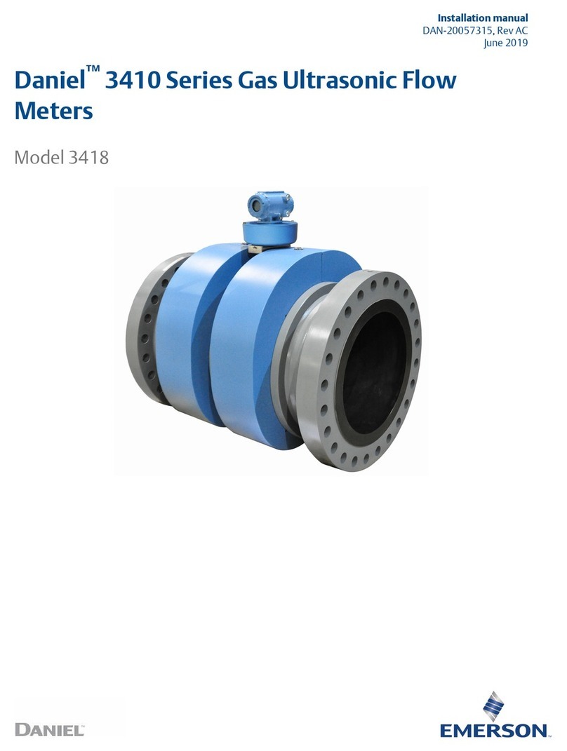
Emerson Daniel 3410 Series installation manual

Cisco
Cisco MDS 9000 Series Installation and configuration note

Steinberg Systems
Steinberg Systems SBS-RL-500G user manual

SANKO
SANKO SM-1100 instruction manual

