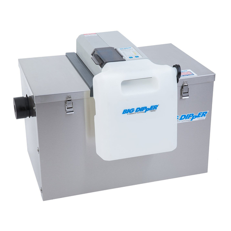
THERMA Big Dipper 51000 Series User manual

51000 Series
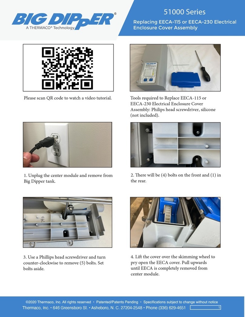
1. Scan this QR code to watch a video tutorial.
2. You will need a Phillips head screwdriver
driver and a replacement EEC (Electrical
Enclosure Cover).
4. There will be (4) bolts on the front and (1)
in the rear.
3. Unplug the center module and remove
from Big Dipper tank.
6. Lift the skimming wheel cover and start
prying open the EEC cover. Pull upwards
until EEC is completely removed from
center module.
5. Use a Phillips head screwdriver and turn
counterclockwise to remove (5) bolts. Set
bolts aside.
Thermaco, Inc. • 646 Greensboro St. • Asheboro, N. C. 27204-2548 • Phone (336) 629-4651
Replacing the Printed Circuit Board PCB-3.
1
Tools required to replace PCB-3 Printed
Circuit Board: Phillips head screwdriver,
mini small at-head screwdriver and needle
nose pliers.
1. Unplug the center module and remove the
center module from the Big Dipper tank.
2. ere will be (4) bolts on the front and (1) in
the rear.
3. Using a Phillips head screwdriver, turn
counter-clockwise and remove (5) bolts. Set
the bolts aside.
4. Li the cover over the skimming wheel to
pry open the EECA cover. Pull upwards until
EECA is completely removed from the
center module.
Please scan QR code to watch a video tutorial.

51000 Series
1. Scan this QR code to watch a video tutorial.
2. You will need a Phillips head screwdriver
driver and a replacement EEC (Electrical
Enclosure Cover).
4. There will be (4) bolts on the front and (1)
in the rear.
3. Unplug the center module and remove
from Big Dipper tank.
6. Lift the skimming wheel cover and start
prying open the EEC cover. Pull upwards
until EEC is completely removed from
center module.
5. Use a Phillips head screwdriver and turn
counterclockwise to remove (5) bolts. Set
bolts aside.
Thermaco, Inc. • 646 Greensboro St. • Asheboro, N. C. 27204-2548 • Phone (336) 629-4651
Replacing the Printed Circuit Board PCB-3.
2
5. Your wiring may dier. Please take a
reference photo to replace wiring to original
conguration.
6. Unplug the ribbon cable.
7. Unplug the motor wire by pressing the tab
inward and pulling out.
8. Using needle nose pliers, unplug the 3
wires – for the heater, safety switch and
jumper – from the board.
9. Using a mini at head screwdriver, turn
counter-clockwise to loosen and remove the
thermistor wires.
10. Remove the printed circuit board.

51000 Series
1. Scan this QR code to watch a video tutorial.
2. You will need a Phillips head screwdriver
driver and a replacement EEC (Electrical
Enclosure Cover).
4. There will be (4) bolts on the front and (1)
in the rear.
3. Unplug the center module and remove
from Big Dipper tank.
6. Lift the skimming wheel cover and start
prying open the EEC cover. Pull upwards
until EEC is completely removed from
center module.
5. Use a Phillips head screwdriver and turn
counterclockwise to remove (5) bolts. Set
bolts aside.
Thermaco, Inc. • 646 Greensboro St. • Asheboro, N. C. 27204-2548 • Phone (336) 629-4651
Replacing the Printed Circuit Board PCB-3.
3
11. Place the new replacement board on the
board groove.
12. Connect the push button ribbon.
13. Connect the motor wire. 14. Connect the 3 wires back on their original
position. Connect the black heater wire on
top, black safety switch on the side and white
jumper wire on the side. (per September 2019
updated wiring.)
15. Insert the thermistor wires inside
the terminals and, using a mini at head
screwdriver, turn clockwise to tighten the
terminals.
16. Apply the provided sealant provided along
the groove of the EECA cover and center
module as illustrated above.

51000 Series
1. Scan this QR code to watch a video tutorial.
2. You will need a Phillips head screwdriver
driver and a replacement EEC (Electrical
Enclosure Cover).
4. There will be (4) bolts on the front and (1)
in the rear.
3. Unplug the center module and remove
from Big Dipper tank.
6. Lift the skimming wheel cover and start
prying open the EEC cover. Pull upwards
until EEC is completely removed from
center module.
5. Use a Phillips head screwdriver and turn
counterclockwise to remove (5) bolts. Set
bolts aside.
Thermaco, Inc. • 646 Greensboro St. • Asheboro, N. C. 27204-2548 • Phone (336) 629-4651
Replacing the Printed Circuit Board PCB-3.
4
22. Set the center module on the Big Dipper
tank and latch the lids on each end. Place the
grease collector on the front end.
20. EECA cover should be ush with the
center module.
21. Flip the center module and secure the 5
bolts used to remove the cover – (4) in the
front and (1) on the rear side.
17. Before re-assembling the EECA, be sure
the main board and electrical plate are
aligned to their holding groove.
18. Connect the push button to the EECA push
button adapter.
19. With the skimming wheel cover open.
Place the EECA on the center module.

51000 Series
1. Scan this QR code to watch a video tutorial.
2. You will need a Phillips head screwdriver
driver and a replacement EEC (Electrical
Enclosure Cover).
4. There will be (4) bolts on the front and (1)
in the rear.
3. Unplug the center module and remove
from Big Dipper tank.
6. Lift the skimming wheel cover and start
prying open the EEC cover. Pull upwards
until EEC is completely removed from
center module.
5. Use a Phillips head screwdriver and turn
counterclockwise to remove (5) bolts. Set
bolts aside.
Thermaco, Inc. • 646 Greensboro St. • Asheboro, N. C. 27204-2548 • Phone (336) 629-4651
Replacing the Printed Circuit Board PCB-3.
5
23. Plug the unit to a power source. Select the
appropriate skimming cycle for your business.
If you continue to experience issues please contact ermaco Technical Support Team at
For additional troubleshooting guides go to www.dipperhelp.com
Other THERMA Industrial Equipment manuals

THERMA
THERMA Big Dipper IS Series Installation instructions

THERMA
THERMA Big Dipper 51000 Series User manual

THERMA
THERMA Trapzilla TZ-1826 Installation and operating instructions

THERMA
THERMA Big Dipper 51000 Series User manual

THERMA
THERMA Big Dipper 40000 Series User manual

THERMA
THERMA Internal Strainer Series Installation instructions


