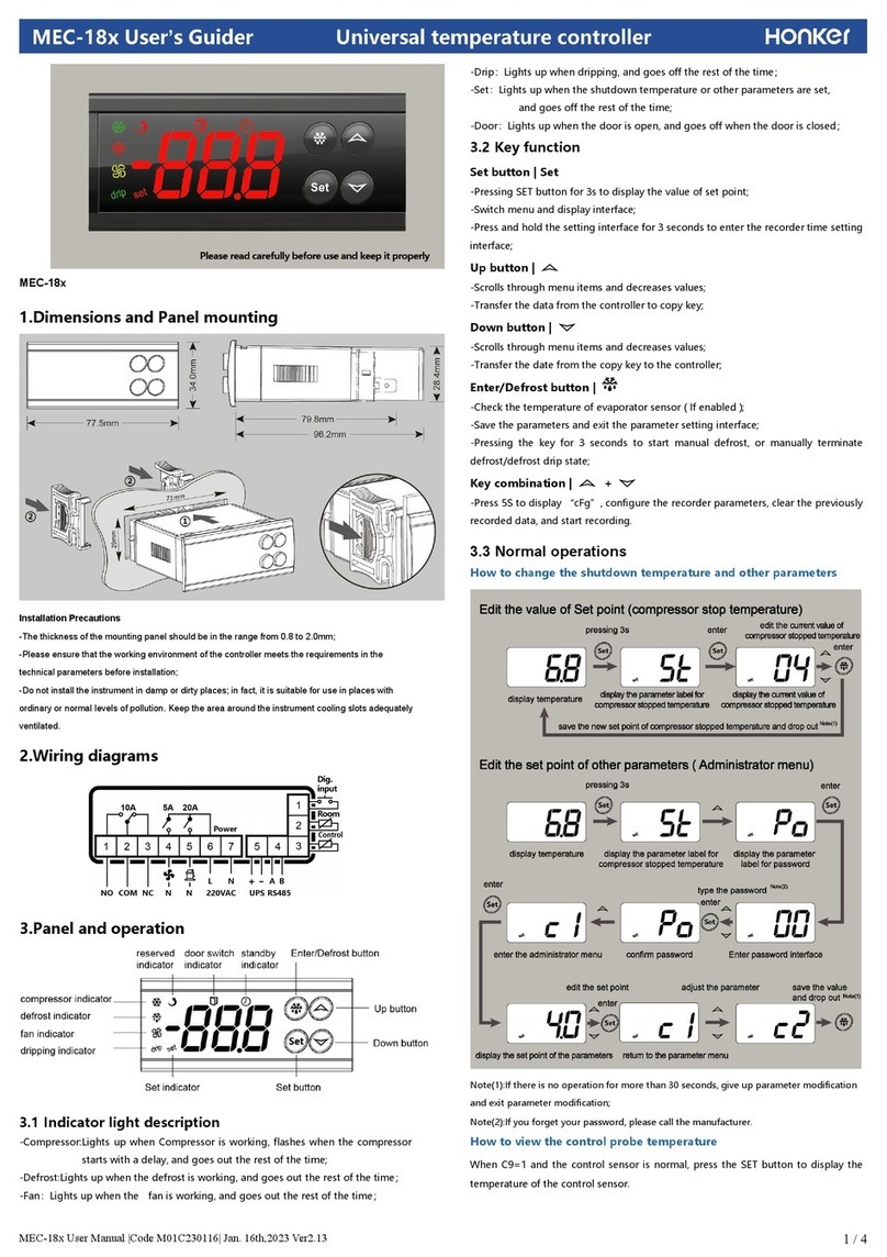
Thermal Care Aquatherm RQT Advanced Instruction Manual


It’s a good idea to record the model and serial number(s) of your equipment and the date
you received it in the User Guide. Our service department uses this information, along
with the manual number, to provide help for the specic equipment you installed.
Please keep this User Guide and all manuals, engineering prints, and parts lists together
for documentation of your equipment.
Date:
Serial Number(s):
Model Number(s):
DISCLAIMER: Neither Thermal Care nor its employees shall be liable for errors contained in this User Guide or
for incidental, consequential damages in connection with the furnishing, performance or use of this information.
Thermal Care makes no warranty of any kind with regard to this information, including, but not limited to, the
implied warranties of merchantability and fitness for a particular purpose.
Please record your equipment’s
model and serial number(s) and
the date you received it in the
spaces provided.
Copyright 2022 l Thermal Care l All rights reserved

Table of Contents I i
Table of Contents
1-1 Introduction
Purpose of the User Guide....................................................................................... 1-2
How the Guide is Organized .................................................................................... 1-2
Your Responsibility as a User .................................................................................. 1-2
Foreword ................................................................................................................ 1-3
ATTENTION: Read This So No One Gets Hurt............................................................ 1-4
Zero Energy State (ZES) .......................................................................................... 1-5
How to Use the Lockout Device (if Equipped) ......................................................... 1-6
2-1 Description
What is the RQT Advanced ..................................................................................... 2-2
Typical Applications ................................................................................................ 2-2
How the RQT Advanced Direct Injection Works ........................................................ 2-4
How the Closed Circuit Common Source Works....................................................... 2-5
RQT Advanced Control Features vs RQT Premium and RQT Standard ...................... 2-6
Specifications: RTQ Advancee ................................................................................. 2-7
3-1 Installation
Unpacking the Boxes .............................................................................................. 3-2
Preparing for Installation......................................................................................... 3-3
Fluid Distribution Piping .......................................................................................... 3-6
Installation - Electrical ........................................................................................... 3-7
Connecting Process and Water Supply Lines Without Purge..................................... 3-8
Connecting Process and Water Supply Lines With Optional Mold Purge Valve
Connections............................................................................................................ 3-9
Connecting the Main Power Source....................................................................... 3-10
Testing the Installation.......................................................................................... 3-11
Initial Setup .......................................................................................................... 3-12
Setpoint................................................................................................................ 3-14
Setting Process Value Source................................................................................ 3-14
Setting Up Your Controller ..................................................................................... 3-15

ii I Table of Contents
4-1 Operation
The RQT Advanced Control...................................................................................... 4-2
Start-up.................................................................................................................. 4-3
Starting the RQT Advanced ..................................................................................... 4-4
Stopping the RQT Advanced.................................................................................... 4-5
Normal Operation.................................................................................................... 4-6
Seal Saver/Auto Cool Stop Sequence Initiation ........................................................ 4-6
Using the Optional Mold Purge Option..................................................................... 4-7
5-1 Maintenance
Maintenance of Your RQT Advanced ........................................................................ 5-2
Preventive Maintenance Schedule .......................................................................... 5-2
Accessing the RQT Advanced Enclosure.................................................................. 5-3
Removing the Pump Motor and Seal
(3/4-2 HP, any frequency and 3HP, 60 Hz units) ....................................................... 5-4
Reassembling the Pump Motor and Seal
(3/4-2 HP, any frequency and 3HP, 60 Hz units) ...................................................... 5-7
Removing the Pump Motor and Seal
(3 HP, 50Hz and 5 to 10 HP, any frequency units)..................................................... 5-9
Reassembling Pump Motor and Seal
(3 HP, 50Hz and 5 to 10 HP, any frequency units)................................................... 5-11
Resetting Pump Overload...................................................................................... 5-12
Replacing Pump Overload..................................................................................... 5-12
Replacing the Heater Contactor............................................................................. 5-13
Replacing the Controller Boards............................................................................ 5-14
System Maintenance ............................................................................................ 5-14
RQT Advanced Controller Abbreviations/Acronyms ................................................ 5-15
Diagnostics Screens ............................................................................................. 5-15
Replacing RTDs .................................................................................................... 5-16
Repairing Cooling Valves....................................................................................... 5-17
Replacing Immersion Heaters ............................................................................... 5-18
Removing the Pump.............................................................................................. 5-22

Table of Contents I iii
6-1 Troubleshooting
Before Beginning .................................................................................................... 6-2
A Few Words of Caution .......................................................................................... 6-3
Identifying the Cause of a Problem.......................................................................... 6-4
Controller Warnings ................................................................................................ 6-5
Controller Alarms .................................................................................................... 6-7
Unit Will Not Power Up .......................................................................................... 6-10
Troubleshooting .................................................................................................... 6-11
Replacing the Heater Contactor............................................................................. 6-13
Checking the RTD................................................................................................. 6-13
AAppendix
We’re Here to Help.................................................................................................. A-1
How to Contact Customer Service........................................................................... A-1
Before You Call........................................................................................................ A-1
BAppendix
PID Parameters....................................................................................................... B-1
CAppendix
Plumbing Diagrams ................................................................................................ C-1
Plumbing Curves .................................................................................................... C-5
DAppendix
External Interfaces.................................................................................................. D-1
EAppendix
Flowmeter Installation Instruction Sheet.................................................................. E-1
FAppendix
Modbus Parameters.................................................................................................F-1

iv I Table of Contents

1
SECTION
1
Introduction
Introduction I 1-1
Introduction
Purpose of the User Guide..................................... 1-2
How the Guide is Organized................................... 1-2
Your Responsibility as a User ................................ 1-2
Foreword............................................................... 1-3
ATTENTION: Read This So No One Gets Hurt .......... 1-4
Zero Energy State (ZES)......................................... 1-5
How to Use the Lockout Device (if Equipped)......... 1-6

1-2 I Introduction
Purpose of the User Guide
This User Guide describes the Thermal Care RQT Advanced and explains step-by-step
how to install and operate this equipment.
Before installing this product, please take a few moments to read the User Guide and
review the diagrams and safety information in the instruction packet. You also should re-
view manuals covering associated equipment in your system. This review won’t take long,
and it could save you valuable installation and operating time later.
How the Guide is Organized
Symbols have been used to help organize the User Guide and call your attention to impor-
tant information regarding safe installation and operation.
Symbols within triangles warn of conditions that could be hazardous to users or could
damage equipment. Read and take precautions before proceeding.
Numbers indicate tasks or steps to be performed by the user.
A diamond indicates the equipment’s response to an action performed by the user or a
situation.
An open box marks items in a checklist.
A circle marks items in a list.
Indicates a tip. A tip is used to provide you with a suggestion that will help you with the
maintenance and the operation of this equipment.
Indicates a note. A note is used to provide additional information about the steps you are
following throughout the manual.
Your Responsibility as a User
You must be familiar with all safety procedures concerning installation, operation, and
maintenance of this equipment. Responsible safety procedures include:
•Thorough view of this User Guide, paying particular attention to hazard warnings,
appendices, and related diagrams.
•Thorough review of the equipment itself, with careful attention to voltage sources,
intended use, and warning labels.
•Thorough review of instruction manuals for associated equipment.
•Step-by-step adherence to instructions outlined in this User Guide.
1
u
r
•
2
0

Introduction I1-3
1
Introduction
Foreword
The RQT Advanced typically consists of a uid pump, electric immersion heater, and
temperature control valve in a compact packaged cabinet for easy location in industrial
applications where uid temperature control is required.
This manual is to serve as a guide for installing, operating, and maintaining the equip-
ment. Improper installation can lead to poor performance and/or equipment damage. We
recommend the use of qualied installers and service technicians for all installation and
maintenance of this equipment.
This manual is for our standard product - in this case, the RQT Advanced TCU equipped
with the an (Enhanced) control. The information in this manual is general in nature.
Unit-specic drawings and supplemental documents are included with the equipment as
needed. Additional copies of documents are available upon request. We strive to maintain
an accurate record of all equipment during the course of its useful life.
Due to the ever-changing nature of applicable codes, ordinances, and other local laws
pertaining to the use and operation of this equipment, we do not reference them in this
manual. There is no substitute for common sense and good operating practices when plac-
ing any mechanical equipment into operation. We encourage all personnel to familiarize
themselves with this manual’s contents. Failure to do so may unnecessarily prolong equip-
ment down time.
Follow good piping practices and the information in this manual to ensure successful
installation and operation of this equipment.
We trust your equipment will have a long and useful life. If you should have any ques-
tions, please contact our Customer Service Department specifying the serial number and
model number of the unit as indicated on the nameplate.

1-4 I Introduction
ATTENTION:
Read This So No One Gets Hurt
We design equipment with the user’s safety in mind. You can avoid the potential hazards
identied on this machine by following the procedures outlined below and elsewhere in
the User Guide.
WARNING: Improper installation, operation, or
servicing may result in equipment damage or personal
injury.
This equipment should be installed, adjusted, and serviced by qualified technical
personnel who are familiar with the construction, operation, and potential hazards
of this type of machine.
All wiring, disconnects, and fuses should be installed by qualified electrical
technicians in accordance with electrical codes in your region. Always maintain
a safe ground. Do not operate the equipment at power levels other than what is
specified on the machine serial tag and data plate.
WARNING: Voltage Hazard
This equipment is powered by three-phase alternating current, as specified on the
machine serial tag and data plate.
A properly sized conductive ground wire from the incoming power supply must be
connected to the chassis ground terminal inside the electrical enclosure. Improp-
er grounding can result in severe personal injury and erratic machine operation.
Always disconnect and lock out the incoming main power source before opening
the electrical enclosure or performing non-standard operating procedures, such
as routine maintenance. Only qualified personnel should perform troubleshooting
procedures that require access to the electrical enclosure while power is on.
WARNING: Compressed Air Hazard
If you use compressed air, you must wear eye protection and observe all OSHA
and other safety regulations pertaining to the use of compressed air. Bleed off
pressure before servicing equipment.
CAUTION: Hot Surfaces
Surface temperatures inside the RQT Advanced can exceed 300°F {149°C}.
Always allow the unit to cool below 100°F {38ºC} before opening, servicing, or
disassembling the unit.

Introduction I1-5
1
Introduction
Zero Energy State (ZES)
CAUTION: Before performing maintenance or repairs on this product, you should
disconnect and lockout electrical power sources to prevent injury from unexpect-
ed energizing or start-up.
During maintenance, it is essential that the system be put into a state which
eliminates the possibility of components making an unexpected and dangerous
movement. This procedure is typically referred to as lockout. After all energy
sources have been neutralized, the system is in the zero mechanical state (ZMS).
This provides maximum protection against unexpected mechanical movement.
The lockout procedure must include all energy sources:
•Electrical power supply
•Compressed air supply
•Potential energy from suspended parts
•Pressurized process uid loop
•Cooling uid supply
•Cooling uid return
•Stored thermal energy
•Any other source that might cause unexpected mechanical movement or
energy release
The following is a recommended Zero Energy State procedure which must be followed
prior to any inspection, or maintenance of the TCU.
1 Turn o the all devices attached to the RQT Advanced.
2 Perform the proper shutdown sequence to the connected equipment and allow all
components (internally and externally) to adequately cool.
3 Disconnect and lock out the primary electrical supply feeding all attached
components.
WARNING: Before removing lockout devices and returning switches to the ON
position, make sure that all personnel are clear of the machine, tools have been
removed and all safety guards reinstalled.
4 Disconnect and lock out the compressed air supply (if equipped).
5 Isolate the RQT Advanced from other uids in the system, such as the main process
loop and the cooling uid supply and return.
6 Bleed o uid pressure that may be present in the various uid containing portions
of the RQT Advanced, keeping in mind that pressure can be the result of increased
temperatures

1-6 I Introduction
How to Use the Lockout Device
(if Equipped)
CAUTION: Before performing maintenance or repairs on this product, you should
disconnect and lockout electrical power sources to prevent injury from unex-
pected energization or start-up. A lockable device may be provided to isolate this
product from potentially hazardous electricity.
WARNING: Before removing lockout devices and returning switches to the ON
position, make sure that all personnel are clear of the machine, tools have been
removed and all safety guards reinstalled.
Lockout is the preferred method of isolating machines or equipment from energy sources.
Your Thermal Care product may be equipped with the lockout device pictured below. To
use the lockout device:
1 Stop or turn o the equipment.
2 Isolate the equipment from the electric power.
3 Turn the rotary disconnect switch to the OFF, or
“O” position.
4 Secure the device with an assigned lock or tag.
5 The equipment is now locked out.
If the machine has no included lockout device, perform the same procedure at the up-
stream device as part of premises electrical system. Incoming cooling water and com-
pressed air (if purge) are additional energy sources that need to be controlled.
NOTE: The incoming power wires on the top of the disconnect switch are still energized, even when
the machine is locked out. It is strongly recommended that electrical energy also be locked out at
the next upstream device if work is going to be performed in the electrical panel.

2
SECTION
2
Description
Description I 2-1
Description
What is the RQT Advanced .................................... 2-2
Typical Applications .............................................. 2-2
How the RQT Advanced Direct Injection Works...... 2-4
How the Closed Circuit Common Source Works ...... 2-5
RQT Advanced Control Features vs RQT Advanced and
RQT Premium......................................................... 2-6
Specifications: RQT Advanced ............................... 2-7

2-2 I Description
What is the RQT Advanced
The RQT Advanced circulates water at a temperature higher than the available water sup-
ply. It will add or remove heat as needed to maintain a uniform temperature setpoint in the
process.
The RQT Advanced is available in single or multiple-zone congurations for process
heating and cooling. Two-zone models can control up to two temperatures at dierent
locations in the process. Two-zone models have common cooling water manifolds and
electrical connections.
Typical Applications
The best model for your application depends on the process temperature you need to
maintain and the quality of the cooling water supply.
RQT Advanced direct injection (DI) models control the temperature by discharging heated
process water or adding cooling water directly from the water supply. DI models are
designed for:
•Process temperatures up to 250°F {121°C} - with options up to 300°F {149°C}.
•Use with chiller water or properly treated and ltered tower or city water.
Check to make sure all piping connections are secure and that all lines are suitable for
water or the coolant in the system at the maximum setpoint temperature and cumulative
pressure rating of the maximum pump pressure rise plus the cooling water pressure.
Make sure that the cooling source is the appropriate
temperature and pressure for your application. In most
cases, the cooling source is between 40°F {4°C} and 85°F
{29°C}. The minimum cooling source uid pressure must
be at least 30 PSI* in order for the unit to start. The maxi-
mum pressure is shown in this chart in order to meet the
pressure limitations of standard 150 psi, high-temperature
industrial hose/plumbing on the discharge side of the
pump.
*Adaptive Maximum Setpoint allows for operation below 30 PSI. This feature will
automatically adjust maximum temperature setpoint based o of supplied pressure with
certain heater and pump combinations.
Pump HP Max Cooling (PSI)
3/4 95
1 90
2 90
3 85
5 75
7.5 65
10 50

Description I2-3
2
Description
Typical Applications (Continued)
The limiting factor regarding the maximum cooling pressure is the presumed 150 PSI Rat-
ing of industry-standard hose. The hose must be able to withstand the maximum possible
process temperature at maximum possible pressure.
Your cooling water pressure may exceed the values shown in the chart ONLY if you are
utilizing specialty high-pressure/ high-temperature hose.
All RQT Advanced units have pressure transducers, and the software will limit setpoint
depending on average cooling source pressure. The pressure relief valve is located on
the “From Process” side of the pump, and will start to discharge if the pressure exceeds
135 psi. If this becomes an issue, install a pressure-regulating valve (available from our
Parts Department) on the cooling water supply line to help regulate the pressure to ensure
it is well below the pressure rating of the pressure relief valve. For further assistance in
installing a pressure-regulating valve, please contact our Customer Service Department.
System Fill Water Chemistry Requirements
The properties of water make it ideal for heat transfer applications. It is safe, non-am-
mable, non-poisonous, easy to handle, widely available, and inexpensive in most industri-
alized areas.
When using water as a heat transfer uid it is important to keep it within certain chem-
istry limits to avoid unwanted side eects. Water is a “universal solvent” because it can
dissolve many solid substances and absorb gases. As a result, water can cause the corro-
sion of metals used in a cooling system. Additionally, dissolved minerals naturally present
in tap water will precipitate out onto the system plumbing at elevated uid temperatures,
forming scale. The life giving properties of water can also encourage biological growth
that can foul heat transfer surfaces. See “Fill Water Chemistry” in the Installation section
of this User Guide.

2-4 I Description
How the RQT Advanced
Direct Injection Works
Direct Injection models maintain the process temperature by electrically heating and/
or injecting cool water supplied to the RQT Advanced by a chiller, tower, or other water
source.
Refer to the Direct Injection Plumbing Diagram for the RQT Advanced in Appendix C of
this User Guide.
1 The temperature of the process uid is
measured as it leaves the unit’s primary
heater tank. The uid then ows through
the “To Process” line A to the mold or
process. The uid returns to the unit
through the “From Process” line B for
reheating or cooling.
2 The temperature of the process uid is
measured as it ows into the mixing tank
through the “From Process” line B.
3 If the “To Process” temperature is above
the setpoint value, the cooling valve opens.
Cool water enters the bottom of the mixing
tank via the “Cooling In” line C. Warm
water ows out of the mixing tank via the
“Cooling Out” line D.
NOTE: The “From Process” or “Remote” can also
be configured as a controlling source.
4 If the “To Process” temperature is below
the setpoint, the heater elements inside the
heater tank are energized.
NOTE: The “From Process” or “Remote” can also
be configured as a controlling source.
5 The pump moves water from the mixing
tank into the heater tank. Pressure can now
be read through pressure transducers.
NOTE: This illustration is for representation
purposes only. Depending on your machine
configuration, your RQT Advanced may have an
additional heater or other options/configurations
not shown here.
FE
D
A
B
C
NOTE: The modulating
valve will be located on the
Cooling OUT line, exiting
the RQT Advanced.

Description I2-5
2
Description
How the Closed Circuit Common Source
Works
Closed Circuit RQT Advanced models maintain the process temperature by electrically
heating and indirectly cooling uid in the process circuit. Cooling water supplied by a
chiller, tower or other water source, is mixed with the process uid only during the initial
lling or when water is needed to make up process uid loss. A brazed-plate heat exchang-
er replaces the mixing tank used on direct injection units.
Refer to the Closed Circuit Common Source Plumbing Diagram for the RQT Advanced in
Appendix C of this User Guide.
NOTE: The modulating
valve will be located
on the Cooling OUT
line, exiting the RQT
Advanced.
1 The temperature of the process uid is measured as it
leaves the unit’s heater tank. The uid then ows through
the “To Process” line to the mold or process. The uid
returns to the unit through the “From Process” line for
reheating or cooling.
2 If the temperature is above the setpoint value, the cool-
ing valve opens. Cool water enters the heat exchanger
via the “Cooling In” line. Process uid is always being
circulated through the process side of the heat exchanger.
The process uid is indirectly cooled via conduction from
the colder water now running through the cooling side of
the heat exchanger. If the measured temperature is below
the setpoint, the heater elements inside the heater tank are
energized.
NOTE: The “From Process” or “Remote” can also be configured as a
controlling source.
3 The pump moves water from the heat exchanger to the
heater tank. Pressure is measured before and after the pump
with pressure transducers. If the “To Process” temperature
is below the setpoint, the heater elements inside the heating
tank are energized.

2-6 I Description
RQT Advanced Control Features vs RQT Premium & Standard
Control Features on the RQT Advanced Control Features on the RQT Premium and RQT Standard
Model RQT Advanced
Direct Injection
Closed Circuit - Common Source
Closed Circuit - Separate Source
Construction
Standard Pump Range 3/4 to 10 Hp
Standard Heater Range 0 to 48 kW
Cast Heater / Pump
Incoloy Heaters
Silicon Carbide Seals
Pressure Gauges
Pressure Transducer
Solid State Heater Relays (SSRS)
Controls
PID Control
Setpoint / Actual Display
Password Protection
Modbus-RTU via RS-485
Modbus-TCP via Ethernet
SPI RS-485 Interface
OPC-UA via Ethernet
Retransmit Process Temp (0-10 VDC)
Auto Restart Capability
Mold Purge (Factory Installed)
Phase Detection Circuit
Choice of Control Points
Seal Saver/Auto Cool Stop
Status / Alarm Lights
Audible Alarm
Strobe Light
Alarm Dry Contacts
Remote RTD Support
Trending
Model RQT PremiumRQT Standard
Direct Injection
Closed Circuit - Common Source
Closed Circuit - Separate Source
Construction
Standard Pump Range 3/4 to 10 Hp 3/4 or 2 Hp
Standard Heater Range 0 to 48 kW 12 kW
Cast Heater / Pump
Incoloy Heaters
Silicon Carbide Seals
Pressure Gauges
Pressure Transducer
Solid State Heater Relays (SSRS)
Controls
PID Control
Setpoint / Actual Display
Password Protection
Modbus-RTU via RS-485
Modbus-TCP via Ethernet
SPI RS-485 Interface
OPC-UA
Retransmit Process Temp
Auto Restart Capability
Mold Purge (Factory Installed)
Phase Detection Circuit
Choice of Control Points
Seal Saver/Auto Cool Stop
Status / Alarm Lights
Audible Alarm
Strobe Light
Alarm Dry Contacts
Remote RTD Support
Trending
Standard
Optional
Control, RQT Advanced
TW-E Thermolator Overlay
Second surface printed 10 mil Bayfol UV-1
3M 468 adhesive backing on white carrier cns 01/27/21 modified for TW-E
Simple On/Off Operation
Easily accessible On/Off
button
LCD Display
Access features with
illuminated control buttons
Easy Access
Easy access to User Parameters
& Settings screens
Auto Restart Capability
Integrated Diagnostics
Run advanced diagnostics whether the
TCU is running or off.
Control temperature
based on temperature at
process supply or return
points, or an average of
the two points.
Purge On/Off button
included on control.
Phase detection
indicates incorrect
pump rotation or an
open electrical leg.

Description I2-7
2
Description
Specifications: RQT Advanced
Specifications
Specication Notes
Models RQT Advanced (direct injection)
‡
RQT Advanced(optional closed circuit)
§
Performance characteristics
Minimum setpoint temperature °F {°C} 40 {4} (with 100% water process fluid), optional lower temperatures
with various glycol mixtures are available - consult factory.
Maximum setpoint temperature °F {°C} 250 {121}, (300 {149} optional
† †
)
§ §
Minimum operating temperature °F {°C} Approximately 20° {11°} above the cooling water inlet temperature
*
Standard cooling valve size inches {mm} 1/2 {12.7} (Cv=2.9) (varies) (other sizes available as optional special order units)
Available pump sizes 0.75, 1, 2, 3, 5, 7.5, 10 Hp {0.56, 0.75, 1.49, 2.24, 3.73, 5.59, or 7.46 kW}
***
Available heater sizes 0, 9, 12, 18, 24, 36 or 48 kW 0, 9, 12, 18, 24, or 36 kW
Connections to/from process NPT (female) 1.50 inches
Connections in/out cooling water NPT (female) 1.00 inches
Pump performance - Consult factory for pump performance characteristics at other operating points.
Pump 3/4 Hp {0.56 kW} 1 Hp {0.75 kW} 2 Hp {1.49 kW} 3 Hp {2.24 kW} 5 Hp {3.73 kW} 7.5 Hp {5.59 kW} 10 Hp {7.46 kW}
Nominal ow gpm {lpm} 50 {189} 55 {208} 75 {284} 85 {322} 100 {379} 120 {454} 150 {568}
Pressure @ nominal ow psi {kg/cm
2
}
† †
20 {1.4} 25 {1.7} 30 {2.1} 32 {2.2} 46 {3.2} 56 {3.9} 65 {4.5}
Shipping weight ranges lb {kg} Weights vary depending on cabinet size, options, and cooling type (DI or CC).
Single Zone Dual Zone
Pump Minimum Maximum Minimum Maximum
0.75 Hp {0.56 kW} 240 {109} 280 {127} 491 {223} 576 {261}
1 Hp {0.75 kW} 245 {111} 290 {132} 499 {226} 584 {265}
2 Hp {1.49 kW} 248 {113} 298 {135} 515 {234} 590 {268}
3 Hp {2.24 kW} 259 {118} 299 {136} 538 {244} 623 {283}
5 Hp {3.73 kW} 302 {137} 352 {160} 629 {285} 699 {317}
7.5 Hp {5.59 kW} 317 {144} 362 {164} 649 {294} 729 {331}
10 Hp {7.46 kW} 329 {149} 379 {172} 683 {310} 763 {346}
*
Lower operating temperatures can be obtained with larger cooling valves.
†
‡
Available in Advanced and Premium models only.
Direct Inject (DI) cooling injects cooling water directly into the process loop upon demand.
§
Closed Circuit Common Source (CCCS) cooling injects cooing water in the process loop only
during the initial lling or when make-up water is needed. Closed Circuit Separate Source
maintains separation via heat exchanger between the cooling and process uids at all times.
**
FLA data for reference purposes only. Does not include any options/accessories on equipment.
For full FLA detail of specic machines/systems, refer to the electrical diagrams of the
equipment order and the nameplate applied.
† †
300°F units require 75 psi minimum inlet coolling source pressure to operate at the highest
temperature at sea level. Higher elevations will require slightly more pressure.
‡ ‡
Smaller frame only available on 3/4HP-3HP units with 0-18kW Heater option, without UL508A
option.
§ §
***
With sucient cooling water pr
10 HP not available for 50Hz.
essure
A B
†
Advanced &
Premium
Only
†
Dimensions inches {mm}
‡ ‡
Cabinet style Single Zone
Small (A)
Single Zone
Large (A)
Dual Zone
Small (B)
†
Dual Zone
Large (B)
†
Height 24.98 {634} 28.98 {735} 24.98 {635} 28.98 {736}
Width 14.09 {358} 14.09 {358} 28.41 {722} 28.41 {722}
Depth 24.09 {612} 26.09 {663} 24.09 {612} 26.09 {663}
Total full load amps per zone
**
Heater 9 kW 12 kW 18 kW
Voltage
460/3/60 208-230/3/60 575/3/60 400/3/50 460/3/60 208-230/3/60 575/3/60 400/3/50 460/3/60 208-230/3/60 575/3/60 400/3/50
Pump size
0.75 Hp {0.56 kW} 12.9 25.8 10.4 14.9 16.7 33.3 13.4 19.2 24.2 48.4 19.5 27.9
1.0 Hp {0.75 kW} 13.2 24.3 10.5 16.0 17.0 34.0 13.5 20.3 24.5 49.1 19.6 29.0
2.0 Hp {1.49 kW} 14.4 28.7 11.5 17.1 18.2 36.2 14.5 21.4 25.7 51.3 20.6 30.1
3.0 Hp {2.24 kW} 15.5 31.5 12.4 18.1 19.3 39.0 15.4 22.4 26.8 54.1 21.5 31.1
5.0 Hp {3.73 kW} 17.6 36.1 14.0 20.6 21.4 43.6 17.0 24.9 28.9 58.7 23.1 33.6
7.5 Hp {5.59 kW} 20.2 41.1 15.9 24.9 24.0 48.6 18.9 29.2 31.5 63.7 25.0 37.9
10.0 Hp {7.46 kW} 23.6 N/A 18.8 N/A 27.4 N/A 21.8 N/A 34.9 N/A 27.9 N/A
Total full load amps per zone
§
Heater 24 kW 36 kW 48 kW
Voltage
460/3/60 208-230/3/60 575/3/60 400/3/50 460/3/60 208-230/3/60 575/3/60 400/3/50 460/3/60 208-230/3/60 575/3/60 400/3/50
Pump size
0.75 Hp {0.56 kW} 31.7 63.4 25.5 36.5 46.8 N/A 37.5 N/A 61.8 N/A 49.6 N/A
1.0 Hp {0.75 kW} 32.0 64.1 25.6 37.6 47.1 N/A 37.6 N/A 62.1 N/A 49.7 N/A
2.0 Hp {1.49 kW} 33.2 66.3 26.6 38.7 48.3 N/A 38.6 N/A 63.3 N/A 50.7 N/A
3.0 Hp {2.24 kW} 34.3 69.1 27.5 39.7 49.4 N/A 39.5 N/A 64.4 N/A 51.6 N/A
5.0 Hp {3.73 kW} 36.4 73.7 29.1 42.2 51.5 N/A 41.1 N/A 66.5 N/A 53.2 N/A
7.5 Hp {5.59 kW} 39.0 78.7 31.0 46.5 54.1 N/A 43.0 N/A 69.1 N/A 55.1 N/A
10.0 Hp {7.46 kW} 42.4 N/A 33.9 N/A 57.5 N/A 45.9 N/A 72.5 N/A 58.0 N/A
Specifications may change without notice. Consult factory for most current information.

2-8 I Description
Page intentionally left blank.
Table of contents
Other Thermal Care Temperature Controllers manuals
Thermal Care
Thermal Care Aquatherm RQT Standard Instruction Manual
Thermal Care
Thermal Care RA Series User manual

Thermal Care
Thermal Care Aquatherm RQT Premium Instruction Manual
Thermal Care
Thermal Care Vactherm RV Instruction Manual
Thermal Care
Thermal Care Aquatherm RQE Instruction Manual
Thermal Care
Thermal Care Oiltherm RO Instruction Manual
Thermal Care
Thermal Care Aquatherm RQE Instruction Manual
