6. Turn on illumination with the LIGHT ON
button located on the left side of the
control bar.
7. Focus the sample with focusing knobs .
8. Optional: To take a picture of the
transmitted light image, click the Capture
button on the control bar.
9. Place the light shield box on the stage,
over the sample.
10.Move the light cube selection lever to the
desired uorescence channel. The channel
bar will highlight the selected light cube.
11.With the Find & Focus tab active, turn on
uorescence illumination using the LIGHT
ON button.
12.Adjust the focus as necessary.
13.Adjust the Illumination Intensity slider on
the control bar as needed.
14.Click the Capture button.
15.Repeat steps 10–14 to capture in each
uorescence channel.
16.Click the Overlay tab to show all channels
in color overlay mode.
17.Adjust Brightness and Contrast for
each channel to bring them into desired
balance.
18.Click the Save button to save the color
image (for details, refer to the EVOS™FL
Imaging SystemUser Guide).
Overview
The EVOS™FL and EVOS™FL Color Imaging
Systems have two types of controls: manual
and onscreen. Manual controls include the the
stage X–Y axis knobs, focusing knobs, objective
selection wheel, phase annuli selector, and the
light cube selection lever. Onscreen controls are
located in the control bar at the bottom of the
display screen. The channel bar at the top of the
display screen shows the selected light cube or
transmitted light position.
2
Helpful Tips
In Find & Focus or Actual Mode, the Color
option (for EVOS™FL, Cat. No. AME4300) can
be turned off to display a grayscale image. This
often shows more details than a color image.
3
Control bar
Channel bar
Basic Operation
Note: For detailed instructions, refer to the
EVOS™FL Imaging SystemUser Guide (Pub.No.
MAN0007988), which is provided on the USB
ash drive. You can also dowload it from the
EVOS™FLImaging System product page at
thermofisher.com.
1. Turn on the instrument using the power
switch on the right side of the base.
2. Plug a USB ash drive into one of the USB
ports on the right side of the instrument.
3. Place the sample on the stage, using a
vessel holder if needed.
4. Set magnication with the objective selection
wheel on the front of the instrument.
5. Pull the light cube selection lever all the
way toward the front of the instrument. The
channel bar will highlight the “Transmitted”
position.
CAUTION! UV HAZARD. Avoid exposure
to light beam and use protective shields.
NEVER look directly at UV light!
4
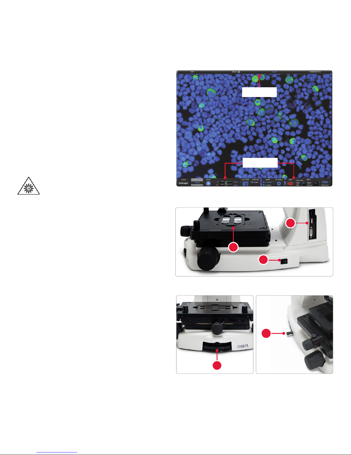
Onscreen Controls
1. Active Channel (highlighted)
2. Login Button
3. Control Bar Tabs
• Find & Focus
• Actual
- Exposure Time Slider
• Overlay
- Overlay Color Dialogue Box
4. Light ON/OFF Button
5. Illumination Slider
6. Exposure Time Slider
7. Image Capture Button
8. Color Option
9. Scalebar/Toolbar Options
10. Setting Control Button
11. Save Image Button
12. Info Display Bar
13. Selected Objective
For EVOS™FL Color (Cat. No. AMEFC4300), use the Color Adjustment button to ne tune your
live image Brightness, Contrast, Saturation, and Hue before capture.
In Find & Focus Mode, the exposure time is set to 100ms to assist real-time focusing, moving the
stage, etc. The illumination level is approximately 60% of the amount used for image capture to
minimize photobleaching and phototoxicity. Clicking Capture results in brighter illumination and a
longer exposure time during image capture to provide a higher-quality image.
In Actual Mode, turning on the illumination results in full-powered illumination and actual exposure
times for live viewing of the sample. With longer exposure times (more than 200ms) there will be a
lag between moving the focus knob and seeing the focus change onscreen.
1
4
910 11
65 12 13
8
7
3
2
1
2
3
5
6
LIGHT ON button Illumination slider Capture button
7
5
Overlay tab Brightness and Contrast
Save button
Color option Color Adjustment button
4