Thermo Scientific EVOS M5000 User manual

For Research Use Only. Not for use in diagnostic procedures.
EVOS™M5000 Imaging System
For Fluorescence and Transmitted Light Applications
Catalog Number AMF5000
Publication Number MAN0017563
Revision C.0

Information in this document is subject to change without notice.
Revision history MAN0017563
Revision
Date
Description
C.0 14 January 2020
Add information about adjustable scale bar, Clear All button for images in the
memory buffer, Hot Pixel Correction, Z-Stack infographics, additional objective
data, additional metadata for PNG and TIFF images, Time/Date setup, automatic
reconnect to WiFi networks and mapped network drives, new authentication code
requirement for first-time Connect™account connection for added login security,
and update the screens throughout the document.
B.0 08 January 2019
Add Connect™account sign in and save, Confluence tool, Time Lapse video save,
review, and playback, EVOS™Onstage Incubator, and EVOS™Image Analysis
sections, update GUI section and the screens throughout the document.
A.0 07 August 2018 New user guide for the EVOS™M5000 Imaging System
Important Licensing Information
These products may be covered by one or more Limited Use Label Licenses. By use of these products, you accept the terms and
conditions of all applicable Limited Use Label Licenses.
Manufacturer: Life Technologies Corporation | 22025 20TH Ave SE | Bothell, WA 98021.
Trademarks
All trademarks are the property of Thermo Fisher Scientific and its subsidiaries unless otherwise specified.
Cy is a registered trademark of GE Healthcare UK Limited. Windows is a registered trademark of Microsoft Corporation. Kimwipes is a
registered trademark of Kimberly-Clark Corporation. Hoechst is a registered trademark of Hoechst GmbH.
© 2020 Thermo Fisher Scientific Inc. All rights reserved.

EVOS™M5000 Imaging System User Guide
1
Contents
About this guide ...................................................................................................................... 4
1. Product information .......................................................................................................... 5
Product description......................................................................................................................................... 5
Standard items included................................................................................................................................. 6
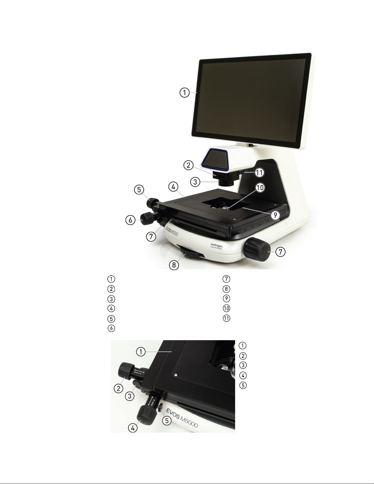
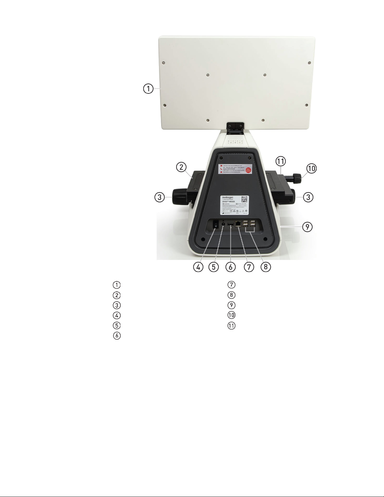
Instrument exterior components and mechanical controls ....................................................................... 7
Graphical user interface (GUI)....................................................................................................................... 9
2. Installation .......................................................................................................................10
Operating environment and site requirements......................................................................................... 10
Prepare for installation ................................................................................................................................. 11
Install the instrument.................................................................................................................................... 11
Turn on the EVOS™M5000 Imaging System ............................................................................................. 15
3. Capture images................................................................................................................17
Overview ........................................................................................................................................................ 17
Capture images in a single channel ............................................................................................................ 18
Capture images in multiple channels ......................................................................................................... 24
4. Analyze and annotate captured images............................................................................25
Display settings and analysis tools ............................................................................................................. 25
Configure display settings ........................................................................................................................... 25
Add and show measurements and annotations........................................................................................ 28
Show cell count.............................................................................................................................................. 29
Measure confluence....................................................................................................................................... 36
Save analysis results...................................................................................................................................... 38
5. Save captured images ......................................................................................................39
Save ................................................................................................................................................................. 39
Quick Save images ........................................................................................................................................ 41
6. Capture time lapse images ..............................................................................................42
Time Lapse tool.............................................................................................................................................. 42
Run a time lapse routine............................................................................................................................... 42
7. Capture Z-Stack ...............................................................................................................54
Z-Stack tool..................................................................................................................................................... 54
Capture Z-stack images ................................................................................................................................ 54
8. Review saved images .......................................................................................................58
Review images ............................................................................................................................................... 58
Analyze saved images .................................................................................................................................. 60

2
EVOS™M5000 Imaging System User Guide
9. Adjust instrument settings...............................................................................................61
Overview ........................................................................................................................................................ 61
Adjust objective settings............................................................................................................................... 62
Calibrate white balance ................................................................................................................................ 64
Set saturated pixel options ........................................................................................................................... 65
General settings ............................................................................................................................................. 66
Configure network settings.......................................................................................................................... 67
Service ............................................................................................................................................................. 70
10. Instrument care and maintenance ...................................................................................72
General care.................................................................................................................................................... 72
Objective lens care......................................................................................................................................... 72
Stage care........................................................................................................................................................ 73
Decontamination procedures....................................................................................................................... 73
Change EVOS™LED light cubes ................................................................................................................. 74
Change the objectives ................................................................................................................................... 75
Calibrate the objectives................................................................................................................................. 76
Appendix A: Troubleshooting .................................................................................................78
Image quality issues...................................................................................................................................... 78
Software interface issues .............................................................................................................................. 79
Mechanical issues .......................................................................................................................................... 79
Appendix B: Graphical user interface (GUI)............................................................................80
Capture tab..................................................................................................................................................... 80
Review tab ...................................................................................................................................................... 86
Settings............................................................................................................................................................ 87
Appendix C: System overview ................................................................................................89
Technical specifications ................................................................................................................................ 89
Operation principles and technical overview............................................................................................ 90
Appendix D: EVOS™Onstage Incubator...................................................................................91
Technical specifications ................................................................................................................................ 92
EVOS™Onstage Incubator components..................................................................................................... 93
Set up the EVOS™Onstage Incubator......................................................................................................... 95
Use the EVOS™Onstage Incubator ........................................................................................................... 100
Appendix E: EVOS™Image Analysis ......................................................................................104

EVOS™M5000 Imaging System User Guide
3
Appendix F: Safety ...............................................................................................................106
Safety conventions used in this document............................................................................................... 106
Symbols on instruments ............................................................................................................................. 107
Safety labels on instruments ...................................................................................................................... 109
General instrument safety .......................................................................................................................... 110
Chemical safety............................................................................................................................................ 111
Chemical waste safety................................................................................................................................. 112
Electrical safety ............................................................................................................................................ 113
Physical hazard safety ................................................................................................................................ 114
Biological hazard safety.............................................................................................................................. 114
Safety and electromagnetic compatibility (EMC) standards................................................................. 115
Documentation and support.................................................................................................116

4
EVOS™M5000 Imaging System User Guide
About this guide
Audience
This user guide is for laboratory staff operating, maintaining, and analyzing data
using the Invitrogen
™
EVOS
™
M5000 Imaging System.
User attention
words
Two user attention words appear in this document. Each word implies a particular
level of observation or action as described below.
Note: Provides information that may be of interest or help but is not critical to the
use of the product.
IMPORTANT! Provides information that is necessary for proper instrument
operation, accurate installation, or safe use of a chemical.
Safety alert words
Three safety alert words appear in this document at points where you need to be
aware of relevant hazards. Each alert word—CAUTION, WARNING, DANGER—
implies a particular level of observation or action, as defined below:
CAUTION! – Indicates a potentially hazardous situation that, if not avoided,
may result in minor or moderate injury. It may also be used to alert against
unsafe practices.
WARNING! – Indicates a potentially hazardous situation that, if not
avoided, could result in death or serious injury.
DANGER! – Indicates an imminently hazardous situation that, if not
avoided, will result in death or serious injury. This signal word is to be
limited to the most extreme situations.

EVOS™M5000 Imaging System User Guide
5
1. Product information
Product description
EVOS
™
M5000
Imaging System
The Invitrogen™EVOS™M5000 Imaging System (Cat. No. AMF5000) is a fully
integrated, digital, inverted imaging system for four-color fluorescence and
transmitted-light applications.
It combines precision optics, a five-objective turret, an 18.5 inch high-resolution
LCD display (1920 × 1080 pixel resolution), and a highly sensitive Sony IMX265
monochrome CMOS camera (2048 × 1536 pixel resolution, 3.2 Megapixels) to
acquire images seamlessly through the intuitive user interface using a mouse for
easy control.
EVOS
™
M5000
Software
The EVOS™M5000 Imaging System is controlled by the integrated Invitrogen™
EVOS™M5000 Software through a graphical user interface (GUI), which is accessed
by the computer mouse and keyboard. The software is pre-installed to the
instrument and starts automatically when the instrument is powered on.
Key features of the EVOS™M5000 Software include:
•Capture:Allows control over every aspect of the system for image capture
through a simple user interface. All images acquired can be saved in BMP, JPG,
PNG, and TIFF formats, or compiled into a video sequence in AVI or WMV
formats.
•Autofocus: Allows autofocus in fluorescence and brightfield modes.
•Z-stacking: Captures a series of images along the z-axis that can be saved
individually or combined into a Z-stack projection with a greater depth of field
than any of the individual source images.
•Time lapse: Allows you to create a time lapse movie using captured images.
•Review:Allows you to review, measure, and annotate captured images.
•Cell count: Allows you to automatically or manually count cells in
fluorescence mode post-acquisition.
•Conflunce: Allows you calculate the percentage confluence of your culture
based on selected reference objects and background.
•Network and Connect™connectivity: Allows Wi-Fi and Ethernet connectivity
to the network and to your Connect™account, Thermo Fisher’s cloud-based
platform, to store and access your data files.
Product use
For Research Use Only. Not for use in diagnostic procedures.

6
EVOS™M5000 Imaging System User Guide
Standard items included
EVOS
™
M5000
Imaging System
•
EVOS™M5000 Imaging System, includes the following components and pre-
installed accessories:
-18.5 in articulated LCD monitor (1920 ×1080 pixel resolution)
-Embedded PC (4 GB RAM)
-Light cube shipping restraint (remove before use)
-Stage lock pin (remove before use)
-EVOS™Condenser Light Shield, 110 mm
-Light cube tool (remove before use)
-Blank light cube (remove before use)
-LED light cubes, as ordered
-Objectives, as ordered
EVOS
™
M5000
Accessories Kit
•
EVOS™M5000 Accessories Kit (located in the instrument box), contains:
-Wireless mouse and keyboard
-USB receiver (for wireless mouse and keyboard connection)
-USB Wi-Fi adaptor (for wireless network connection to Connect™
applications and mapped network drives)
-USB 3.0 flash drive, 16 GB (for image storage, and preloaded with user
documentation)
-EVOS™Vessel Holder, Two 25 × 75 mm slides (Cat. No. AMEPVH001)
-EVOS™Vessel Holder, Universal (Cat. No. AMEPVH009)
-EVOS™Calibration Slide (Cat. No. AMEP4720)
-EVOS™Light Shield Box
-UV shield assembly
-Condenser Slider, Block (Cat. No. AMEP4688)
-Condenser Slider, 4X Pupil (Cat. No. AMEP4738)
-Condenser Slider, Diffusion for Brightfield Applications (Cat. No.
AMEPDFS1)
-Universal power supply (12 V, 5 A) and power cord (type B, North America)
-EVOS™Dust Cover
-Accessories box with adjustable compartments
-Hex driver, 2 mm
-Mouse pad
EVOS
™
M5000 user
documentation
•
EVOS™M5000 Quick Start Guide, printed (Pub. No. MAN0017765)
•EVOS™M5000 Imaging System Installation Guide, printed (Pub. No. MAN0017783)
•Pre-loaded to USB 3.0 flash drive (located in the accessories box):
-EVOS™M5000 User Guide (Pub. No. MAN0017763)
-EVOS™M5000 Quick Start Guide (Pub. No. MAN0017765)
-EVOS
™
M5000 Imaging System Installation Guide (Pub. No. MAN0017783)

EVOS™M5000 Imaging System User Guide
7
Instrument exterior components and mechanical controls
Front view
LCD monitor Focusing knobs
Condenser slider slot Objective selection wheel
Condenser head Vessel holder
Mechanical X-Y stage Objective
Stage X-axis positioning knob Phase annuli selector
Stage Y-axis positioning knob
Stage positioning
knobs and brakes
Mechanical X-Y stage
Stage X-axis positioning knob
Stage brake for X-axis
Stage Y-axis positioning knob
Stage brake for Y-axis

8
EVOS™M5000 Imaging System User Guide
Rear view
LCD monitor Network port
Mechanical X-Y stage USB-A 2.0 ports (4×)
Focusing knobs USB 3.0 port (1×)
Power switch Stage X-axis positioning knob
4-pin power input port (12 VDC, 5 A) Stage Y-axis positioning knob*
Display port (video output) * Not visible in this perspective.

EVOS™M5000 Imaging System User Guide
9
Graphical user interface (GUI)
GUI layout
The GUI of the system consists of the Viewing area on the left and Capture and
Review tabs and the Settings and Virtual keyboard buttons on the right. Each tab
and button opens the controls necessary to execute the selected function.
Sign In/User:Allows you to sign in to your Connect™account, Thermo Fisher’s cloud-
based platform, for image storage and analysis with the EVOS™Image Analysis
application.
Viewing area: Displays the sample.
Capture tab: Contains the controls for image capture.
Review tab: Allows you to review and annotate captured images.
Keyboard button: Opens the virtual keyboard.
Settings button: Opens the Settings tabs, which allow you to select and adjust basic
and advanced system settings.
Note: For more information and detailed descriptions of GUI controls, see
“Appendix B: Graphical user interface (GUI)”, page 80.
Note: For more information on the EVOS™Image Analysis application, see
“Appendix E: EVOS™Image Analysis”, page 104.

10
EVOS™M5000 Imaging System User Guide
2. Installation
Operating environment and site requirements
•The dimensions of the EVOS
™
M5000 Imaging System are 18 × 23 × 18 in
(W×H×D) (46 × 59 × 46 cm). The system requires a benchtop of approximately
36 × 36 in (92 ×92 cm).
•If the system includes the optional EVOS™Onstage Incubator (Cat. No.
AMC1000), then add 16 in (40 cm) to the width of the bench.
•Allow at least 5 cm (2 in) free space at the back of the instrument to allow for
proper ventilation and prevent overheating of electronic components.
•Place the EVOS™M5000 Imaging System on a level surface away from
vibrations from other pieces of equipment. Tabletop centrifuges, vortex mixers,
and other laboratory equipment can vibrate the instrument during a run and
cause a decrease in instrument performance.
•The EVOS™M5000 Imaging System should be installed away from direct light
sources such as windows. Ambient light can enter the imaging path and affect
the image quality.
•Operating temperature range: 4°–32°C (40°–90°F).
•Relative humidity range: 0–90%.
•Operating power: 100–240 VAC, 1.8 A
•Frequency: 50–60 Hz
•Electrical input: 12 VDC, 5 A
IMPORTANT! Do not position the instrument so that it is difficult to turn off the
main power switch located on the back of the instrument base (see page 8). In case
of an instrument malfunction, turn the main power switch to the OFF position and
disconnect the instrument from the wall outlet.
Hood setup
The EVOS™M5000 Imaging System fits in cell culture hoods that are at least 24 in
(61 cm) deep and 36 in (92 cm) high with a 30 in (76 cm) opening. If your cell
culture hood is smaller, it may be possible to fit the instrument by turning it at a
slight angle.

EVOS™M5000 Imaging System User Guide
11
Prepare for installation
Receive and inspect
the shipment
1. Verify that the items shown on the shipping list are the same items that you
ordered at the time of purchase.
2. Carefully inspect the shipping containers and report any damage to the
Thermo Fisher Scientific service representative. Record any damage or
mishandling on the shipping documents.
Move the
instrument to the
installation site
1. Clear the installation site of all unnecessary materials.
2. If possible, move the crated instrument and other shipping containers to the
installation site.
CAUTION! PHYSICAL INJURY HAZARD. Lift or move the instrument using
proper lifting techniques. We recommend that you lift or move the crated
instrument with the assistance of others and the use of appropriate moving
equipment. Improper lifting can cause painful and permanent back injury.
Depending on the weight, moving or lifting an instrument may require
two or more persons.
Install the instrument
Unpack the
instrument
1. Open the shipping box and remove the accessory box.
2. Carefully lift the instrument out of the box by grasping it firmly with both
hands under the support arm.
3. Place the instrument on a flat, level surface that will be free from vibration and
leave enough room around it for the stage to move freely.
4. Tilt the LCD monitor upright.
5. Examine the instrument carefully for damage incurred during transit.
6. Unpack the accessories box and verify all parts are present. See page 6 for the
list of standard items included in the shipment.
IMPORTANT! Do not subject the EVOS™M5000 Imaging System to sudden impact
or excessive vibration. Handle the instrument with care to prevent damage.
Note: Contact your distributor if anything is missing. If you do not have your
distributor information, contact Technical Support (page 116). Damage claims
must be filed with the carrier; the warranty does not cover in-transit damage.
Note: Make sure to set aside packaging and foam for future transport and storage.
Re-install the stage lock pin and the light cube shipping restraint before moving
or transporting the instrument. Always ensure that the instrument is properly
cushioned and braced to prevent damage.

12
EVOS™M5000 Imaging System User Guide
Remove shipping
restraints
The EVOS™M5000 Imaging System is equipped with two shipping restraints
(stage lock pin and light cube shipping restraint) to protect the instrument from
shock and vibration during transport. You must remove the shipping restraints
before you power on the EVOS
™
M5000 Imaging System.
Stage lock pin
Light cube shipping
restraint
Light cube tool
1. Pull firmly to remove the stage lock pin and release the X- and Y-axis brakes.
2. Using the X-axis and Y-axis stage positioning knobs, move the stage back to
obtain access to the light cube shipping restraint, which is centered under the
back of the stage.
Note: The light cube shipping restraint is secured with the light cube tool to
the blank light cube installed in the light cube turret. Used together, they
immobilize the light cube turret to protect it during transport.
Before stage reposition
After stage reposition
3. Unscrew and remove the light cube tool, which secures the shipping restraint
block to the blank light cube.
4. Remove the shipping restraint block and store it in the accessories box.
Removal of the restraint block provides access to the blank light cube in the
light cube turret.
Note: The blank light cube is red and does not have the grooved copper top
of the LED light cubes.

EVOS™M5000 Imaging System User Guide
13
Blank light cube
Thread hold
Screws
5. Using the light cube tool, loosen the two screws that secure the blank light cube
to the instrument. You do not need to remove the screws.
6. Screw the light cube tool to the thread hold on the light cube, then lift the blank
light cube up and out of the light cube turret. Store the blank light cube and the
light cube tool in the accessories box.
7. Place the desired EVOS
™
Vessel Holder on the stage.
Note: Store the shipping restraints and the light cube tool for future use in the
accessories box provided with your system. Always re-secure the X-Y stage with
the stage lock pin and re-install the light cube restraint before moving the
instrument.
IMPORTANT! Before changing light channels, ALWAYS verify the light cube
restraint has been removed. Attempting to change the light channels while the
restraint is in place can seriously damage the mechanism. This type of damage is
not covered by manufacturer’s warranty.
Install the UV light
shield
1. Verify that the EVOS™Condenser Light Shield is installed on the condenser
assembly. The condenser shield is pre-installed and helps reduce the potential
effects of overhead lighting on your image.
2. Pull the condenser light shield out from the condenser head.

14
EVOS™M5000 Imaging System User Guide
3. Secure the UV light shield mount to the top of the condenser light shield using
the two screws supplied with the UV shield assembly (not the protruding
screws on the mount).
4. Clip the condenser light shield with the attached UV light shield mount back
onto the condenser head.
5. Peel the protective paper from the UV light shield, then slide the orange UV
light shield over the two protruding screws on light shield mount to attach it
to the instrument.
Note: The UV light shield is provided as a safety feature and should be installed
whenever the unit is in operation. The UV light shield is removable for access to
the condenser sliders used in transmitted light mode. Simply unhook it from the
screws on the UV light shield mount.
Connect the
instrument
1. Confirm that the power switch is OFF (located on the back; see page 8).
2. Connect the USB receiver for the wireless mouse and keyboard to an
available USB-A 2.0 port (page 8).
3. Connect the power adaptor and power cord. Ensure a tight connection
4. Plug the power adaptor into the power input port on the instrument (page 8).
5. Plug the power cord into a power outlet and check for the light on the power
supply.

EVOS™M5000 Imaging System User Guide
15
Turn on the EVOS™M5000 Imaging System
1. Turn the instrument power switch (located on the back; see page 8) to the ON
position.
2. When the Capture tab is displayed, the EVOS™M5000 Imaging System is
ready to use.
IMPORTANT! All shipping restraints must be removed before turning on the
EVOS™M5000 Imaging System to prevent damage (page 12).
Connect to a Wi-Fi
network
You can connect the EVOS™M5000 Imaging System to a network via an Ethernet
cable or Wi-Fi adaptor and save captured images directly to shared folders on the
network. You can also connect to your Connect™account, Thermo Fisher’s cloud-
based platform, to store your image files and analyze them with the EVOS™Image
Analysis application (page 16).
For instructions on how to connect to a Wi-Fi network and how to map a network
drive to save your images, see “Configure network settings”, page 67.
Set date and time
For instructions on how to configure the date and time to the local time, see “Set
date and time”, page 70.

16
EVOS™M5000 Imaging System User Guide
Sign in to your
Connect™account
Connecting to your Connect™account, Thermo Fisher’s cloud-based platform,
allows you to save captured images in your unique user account in addition to
local storage.
Note: You must have a Connect™account or create one to sign in. To create your
Connect™account online, go to thermofisher.com/connect.
1. Click the Sign In button on the top left corner of the screen to
open the Connect to the Cloud dialog.
2. Enter your Connect™user name and password, then click Sign In.
When you connect to your Connect™account, the Sign In button
changes to display your user name.
3. To sign out of your Connect™account, click your User button to
open the Sign Out dialog, then click Sign Out.
Note: You can choose to save captured images to your Connect™account in
addition to local storage. Images saved to your account in the Connect™platform
can then be viewed and analyzed with the EVOS™Image Analysis application.
For more information on the EVOS™Image Analysis application, see “Appendix E
:
EVOS™Image Analysis”, page 104.

EVOS™M5000 Imaging System User Guide
17
3. Capture images
Overview
Capture tab
The basic functions of the EVOS™M5000 Imaging System, such as viewing the
sample, setting optimal focus, and capturing and saving images are performed in
the Capture tab, which is the first screen after start-up.
Workflow
Select objective and light source
Adjust brightness
Focus on the sample
Find the region of interest
Capture image in a single channel
Analyze and annotate captured images
Show cell count
Save

18
EVOS™M5000 Imaging System User Guide
Capture images in a single channel
Select objective and
light source
1. Place the vessel containing your sample on the stage using the appropriate
vessel holder.
Note: When capturing images in fluorescence channels, place the light shield
box on the stage, over the sample. This is important for optimal image quality.
2. Set the magnification using the objective selection wheel (page 7).
3. Select the desired Phase option by turning the phase annuli selector (page 7).
Available options are:
•Oly 4×:Used for low magnification objectives (Olympus™4× PH)
•4×/10×: Used for medium magnification objectives (EVOS™4×/10× PH)
•20×/40×: Used for high magnification objectives (EVOS™20×/40× PH)
•Brightfield (phase contrast off)
The active objective and phase ring information is displayed above the
Channel buttons.
4. Select a Channel to turn on the excitation light and enter the instrument in the
Live mode. In this example, the DAPI channel has been selected.
In the Live mode, you can adjust the brightness and configure display settings
for the selected channel, and set the focus on the sample.
Note: You can select only one light source at a time for Live mode to adjust
brightness and set focus. However, you can display and capture multiple
channels simultaneously.
Other manuals for EVOS M5000
3
This manual suits for next models
1
Table of contents
Other Thermo Scientific All In One Printer manuals

Thermo Scientific
Thermo Scientific EVOS M5000 User manual

Thermo Scientific
Thermo Scientific iBright CL1500 User manual

Thermo Scientific
Thermo Scientific Invitrogen FLoid User manual

Thermo Scientific
Thermo Scientific EVOS M5000 User manual

Thermo Scientific
Thermo Scientific iBright CL1500 User manual

Thermo Scientific
Thermo Scientific iBright CL750 User manual

Thermo Scientific
Thermo Scientific invitrogen EVOS FL User manual