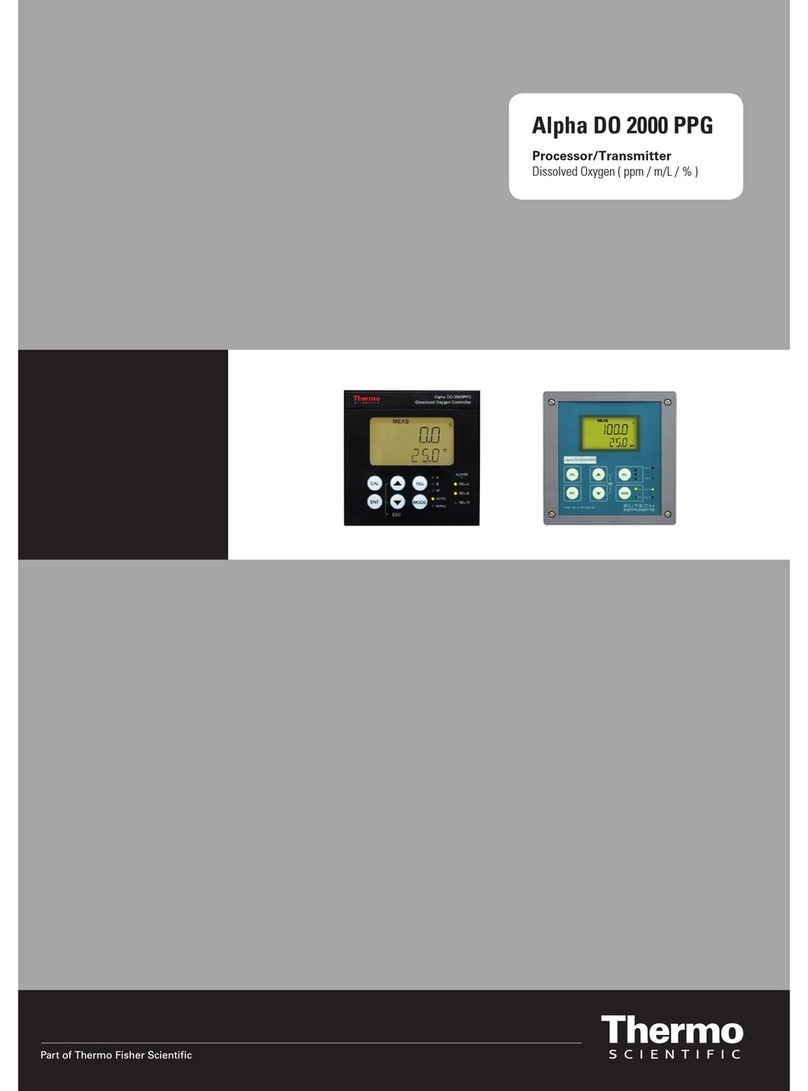
Thermo Scientific Alpha RES 1000 User manual

Alpha RES 1000
Controller/Transmitter
Resistivity

ROSS and the COIL trade dress are trademarks of Thermo Fisher Scientific Inc. U.S. patent 6,793,787.
AQUAfast, Cahn, ionplus, KNIpHE, No Cal, ORION, perpHect, PerpHecT, PerpHecTion, pHISA, pHuture,
Pure Water, Sage, Sensing the Future, SensorLink, ROSS, ROSS Ultra, Sure-Flow, Titrator PLUS and
TURBO2 are registered trademarks of Thermo Fisher.
1-888-pHAX-ION, A+, All in One, Aplus, AQUAsnap, AssuredAccuracy, AUTO-BAR, AUTO-CAL, AUTO
DISPENSER, Auto-ID, AUTO-LOG, AUTO-READ, AUTO-STIR, Auto-Test, BOD AutoEZ, Cable-Free,
CERTI-CAL, CISA, DataCOLLECT, DataPLUS, digital LogR, DirectCal, DuraProbe, Environmental Product
Authority, Extra Easy/Extra Value, FAST QC, GAP, GLPcal, GLPcheck, GLPdoc, ISEasy, KAP,
LabConnect, LogR, Low Maintenance Triode, Minimum Stir Requirement, MSR, NISS, One-Touch, One-
Touch Calibration, One-Touch Measurement, Optimum Results, Orion Star, Pentrode, pHuture MMS,
pHuture Pentrode, pHuture Quatrode, pHuture Triode, Quatrode, QuiKcheK, rf link, ROSS Resolution,
SAOB, SMART AVERAGING, Smart CheK, SMART STABILITY, Stacked, Star Navigator 21, Stat Face,
The Enhanced Lab, ThermaSense, Triode, TRIUMpH, Unbreakable pH, Universal Access are trademarks
of Thermo Fisher.
Guaranteed Success and The Technical Edge are service marks of Thermo Fisher.
PerpHecT meters are protected by U.S. patent 6,168,707. PerpHecT ROSS electrodes are protected by
U.S. patent 6,168,707. ORION Series A meters and 900A printer are protected by U.S. patents 5,198,093,
D334,208 and D346,753.ionplus electrodes and Optimum Results solutions are protected by U.S. patent
5,830,338.ROSS Ultra electrodes are protected by U.S. patent 6,793,787.ORP standard is protected by
U.S. patent 6,350,367. No Cal electrodes are protected by U.S. patent 7,276,142.© 2009 Thermo Fisher
Scientific Inc. All rights reserved. All trademarks are the property of Thermo Fisher Scientific Inc. and its
subsidiaries.The specifications, descriptions, drawings, ordering information and part numbers within this
document are subject to change without notice.This publication supersedes all previous publications on this
subject.

Preface
This instruction manual serves to explain the use of the Alpha RES 1000 series Resistivity
controller/transmitter. The manual functions in two ways: firstly as a step by step guide to help the user
operate the instrument. Secondly, it serves as a handy reference guide. This instruction manual is written
to cover as many anticipated applications of the Alpha RES 1000 Resistivity controller/transmitter. If you
have doubts in the use of the instrument, please do not hesitate to contact the nearest Thermo Scientific
Authorised Distributor.
The information presented in this manual is subject to change without notice as improvements are made,
and does not represent a commitment on part of Thermo Fisher Scientific.
Thermo Fisher Scientific cannot accept any responsibility for damage or malfunction of the unit due to
improper use of the instrument.
All rights reserved.

TABLE OF CONTENTS
1INTRODUCTION.................................................................................................1
1.1 DESCRIPTION OF UNIT ....................................................................................1
1.2 APPLICATIONS................................................................................................1
2ASSEMBLY AND INSTALLATION.....................................................................2
2.1 MEASUREMENT AND CONTROL SYSTEM............................................................2
2.2 UNIT DIMENSIONS ..........................................................................................2
3ELECTRICAL CONNECTION.............................................................................3
3.1 CONNECTION DIAGRAM...................................................................................3
3.2 BACK PANEL..................................................................................................4
4OVERVIEW.........................................................................................................5
4.1 KEYPAD AND DISPLAY.....................................................................................5
4.1.1 Keypad................................................................................................................... 5
4.1.2 Display ................................................................................................................... 5
4.2 FUNCTION GROUPS ........................................................................................6
4.3 CONTROL CONCEPT .......................................................................................7
5MEASUREMENT ................................................................................................8
5.1 ISPLAY IN MEASUREMENT MODE ....................................................................8D
5.1.1 Check electrode performance................................................................................ 8
5.1.2 Checking set points................................................................................................ 8
5.2 ECURITY CODES...........................................................................................8S
5.2.1 How to enter and change parameters in Calibration mode.................................... 8
5.2.2 How to enter and change parameters in Advanced Setup mode .......................... 9
6CALIBRATION MODE......................................................................................10
6.1 RESISTIVITY CALIBRATION.............................................................................10
7ADVANCED SET-UP MODE ............................................................................10
7.1 TEMPERATURE COEFFICIENT SUB-FUNCTION...................................................11
7.1.1 Selecting Pure-water or Linear Temperature Coefficient..................................... 11
7.2 EMPERATURE CALIBRATION (ATC MODE ONLY)..............................................12T
7.2.1 Setting manual temperature compensation ......................................................... 12
7.3 ONTROL RELAY A/CONTROL RELAY B(SP1/SP2) SUB-FUNCTION ..................13C
7.3.1 Entering the Set point 1 (Set point 2) sub-function .............................................. 13
7.3.2 Selecting the set point values .............................................................................. 13
7.3.3 Choosing High or Low set points ......................................................................... 13
7.3.4 Selecting a hysteresis (dead band) value (0.000 to 0.200 m
Ω
or 0.00 to 2.00 m
Ω
)13
7.3.5 Setting an on-delay time lag................................................................................. 14
7.3.6 Setting an off-delay time lag................................................................................. 15
7.4 ONTROLLER (CNTR)SUB-FUNCTION .............................................................15C
7.4.1 Entering the Controller sub-function..................................................................... 15
7.4.2 Choosing the controller type (limit or proportional) .............................................. 15
7.4.3 Choosing break/make contact relay type............................................................. 16
7.4.4 Selecting proportional range value Xp................................................................. 16
7.4.5 Maximum Pulse Length (tPL) or Maximum Frequency (FPF)..............................17

7.5 MEASUREMENT RANGE SUB-FUNCTION...........................................................17
7.5.1 Entering the Measuring Range sub-function........................................................17
7.5.2 Selecting Measuring Range sub-function ............................................................ 17
7.5.3 Measurement Range available in the Controller.................................................. 18
7.5.4 Current Output (rng) sub-function........................................................................ 18
7.5.5 Choosing the output type..................................................................................... 18
7.5.6 Selecting Resistivity value at 0(4)mA................................................................... 18
7.5.7 Selecting Resistivity value at 20mA..................................................................... 19
7.6 ONFIGURATION (CONF)SUB-FUNCTION ........................................................19C
7.6.1 Entering Configuration sub-function..................................................................... 19
7.6.2 Selecting Filter Function and the Alarm or Wash Function.................................. 19
7.6.3 Selecting the alarm time lag (if the relay 3 is set to Alarm).................................. 20
7.6.4 Selecting steady or pulse contact for the alarm relay (if the relay 3 is set to Alarm)20
7.6.5 Wash Contact (if the relay 3 is set to Wash)........................................................ 20
7.6.6 Input Line Resistance Adjust................................................................................ 21
7.6.7 Reverting to factory default settings..................................................................... 21
7.7 ALIBRATION (CAL) SUB-FUNCTION ...............................................................21C
7.7.1 Entering Calibration mode from Advanced Set-up mode..................................... 21
8AUTO/MANUAL MODE....................................................................................22
8.1 AUTO MODE (MODE AFTER SWITCH-ON)...........................................................22
8.2 MANUAL MODE.............................................................................................22
9TECHNICAL SPECIFICATIONS.......................................................................23
10 GENERAL INFORMATION...........................................................................24
10.1 PACKAGING .................................................................................................24
10.2 RETURN OF GOODS......................................................................................24
10.3 GUIDELINES FOR RETURNING UNIT FOR REPAIR ..............................................24
11 APPENDICES...............................................................................................25
APPENDIX 1–JUMPER POSITIONS .............................................................................25
APPENDIX 2–CONDUCTIVITY /RESISTIVITY OF VARIOUS AQUEOUS SOLUTIONS AT 25OC26
APPENDIX 3-SIMPLE EXPLANATION ON THE FUNCTION OF HYSTERESIS ........................26
APPENDIX 4–PURE WATER CURVE...........................................................................27

Operating Instructions Alpha RES 1000
1
1 Introduction
1.1 Description of Unit
Thank you for purchasing the Alpha ¼ DIN Alpha RES 1000 Resistivity process controllers. This unit is
used for measuring the Resistivity of a solution in mega-ohms. You can use this unit to measure Resistivity
with limit control. This controller has many user-friendly and safety features which include:
•Menu-driven program that simplifies set-up
•Two ranges of Resistivity measurements-software selectable (Section 7.5.3).
•Built-in memory backup to ensure that calibration data and other information are not erased if
power supply fails
•Automatic temperature compensation (ATC) with Pt100 or Pt 1000
•Manual temperature compensation with independent setting for calibration and process
temperature
•Temperature coefficient variable between 0.00 to 10.00 % per oC. Separate pure water compensation
curve stored in memory. Reference temperature at 25oC.
•0 to 1999 second time delay adjustment on all relays – minimise false alarms
•Separately adjustable high and low set point hysteresis (dead bands) prevent chattering of relays
around the set points. Selectable Filter function stabilises rapid measurement changes.
•Three control modes: limit, proportional pulse length or proportional pulse frequency.
•Large dual display LCD for easy reading with clear multiple annunciators, alarm status and
operational message annunciators
•Two switching contacts as set-point triggering relays and an alarm output relay
•Separate alarm relay alerts you when set points have exceeded the limits and if the Pt100/Pt1000
wires are broken or disconnected during the ATC function
•Hold function freezes output current (0/4...20mA) and releases control relays
•LED indicators signal control activities to monitor controller status from a distance
•Protection against electromagnetic interference - galvanically isolated 0/4..20mA output provides
safety for data logging and control purposes
1.2 Applications
Use this controller in panel mounted enclosures for applications in Pure water and R.O. Systems.

Operating Instructions Alpha RES 1000
2
2 Assembly and Installation
2.1 Measurement and Control System
A typical measurement system consists of:
•an Alpha RES 1000 process controller
•a suitable Resistivity electrode with the appropriate Cell constant and integrated temperature sensor Pt
1000 or Pt 100,
•an immersion, flow or process assembly
•a final control element such as pump or valve and
•a chart recorder
Power Mains
(220/110 VAC)
rollerAlpha RES 1000 Cont
Flow Assembly
to Dosing Pumps
Process Assembly
with Electrode
Chart Recorder
Pt100/Pt1000
Temperature Sensor
A
lpha RES 1000
A
larm / Siren
System
2.2 Unit Dimensions
The field-tested control panel housing is 96 x 96 mm; with protection class IP 54 (front).
max. 175 max. 45
Mounting Cut-Out
Flat Gasket (1mm)
(TobeInsertedByCustomer)
Note: The Ta
p
ed Co
r
ne
r
sHavetoBeOnTo
p
92
32
56
96
92+ 0.5
92+ 0.5

Operating Instructions Alpha RES 1000
3
3 Electrical Connection
3.1 Connection Diagram
Signal OutputputHold In
Alarm
Relay 2
Relay 1
Power Mains
Res.
mA
-
+
PE/S
14 15 17
15 16
ror conditions
ty
PEAC: NL
1
25
4
36
78 9 10 11 12 13
* ) indicated contact positions are for currentless or no er
Pt100/Pt1000
Signal Input Resistivi
S/
V
PE/S
Res.
18 19 20 21 22
S/S/

Operating Instructions Alpha RES 1000
4
3.2 Back Panel
The back panel consists of two connectors. The first connector is the 17-way PCB edge connector and the
other is the 5-way connector.
Connection for the 17-way screw terminals (from left to right):
1. AC mains live wire 10. Alarm/Wash relay resting position (NO)
2. AC mains neutral wire 11. Alarm/Wash relay common
3. AC mains protective earth wire 12. Alarm/Wash relay working position (NC)
4. Relay 1 relay resting position (NC) 13. Hold function switch terminal 1
5. Relay 1 relay common 14. Hold function switch terminal 2
6. Relay 1 relay working position (NO) 15. No connection
7. Relay 2 relay resting position (NC) 16. 0/4 - 20 mA for -ve connection
8. Relay 2 relay common 17. 0/4 - 20 mA for +ve connection
9. Relay 2 relay working position (NO)
Connections for the 5-way screw terminals:
18. Pt1000/Pt100 lead 1 terminal (red)
19. Pt1000/Pt100 sense lead terminal (short 18 & 19 if using a two-wire system)
20. Pt1000/Pt100 lead 2 terminal (green)
21. Resistivity lead 1 (black)
22. Resistivity lead 2 (white)
*cable wire colours stated above are applicable to EC-CS10 series. For other electrodes, please check
electrode specifications.
Pt100
/
RELAY1
LNPE
(F)
FUSE 250VAC
IMPORTANT: The
Alarm relay functions
as an “Active Low”
device i.e. it switches
OFF under Alarm
condition. Therefore
the Alarm display
device should be
connected to the ‘NC’
contacts of the relay. If
the relay is configured
as “wash”, then it
works in the ‘Active
High’ mode. Therefore
the wash pump has to
be connected across
its “NO” contacts.
HOLD
ALARM
RELAY2
Pt1000
NC -+
cell
J2
100 mA

Operating Instructions Alpha RES 1000
5
4 Overview
4.1 Keypad and Display
4.1.1 Keypad
•Perform rapid calibration
•Allows entry to Set up mode
•Select individual functions within the function group of Set up mode
•Store input data in the Set up mode
•Start calibration in the calibration mode
•Select various function groups in the Set up mode.
•Set parameters and numerical values in sub functions of Set up mode
If pressed continuously, the setting speed increases
•Control the relays in the MANUAL function
•Return to the Measurement mode when both keys are pressed together
•Switch between AUTO and MANUAL relay operation using a code
•Display set-point values for the switch contacts in AUTO operation mode
•Switch between RELAY A and RELAY B in MANUAL relay operation mode
4.1.2 Display
The LCD display features two numerical displays that show status messages and measured values for easy,
quick reference. The display provides short-text information for setting parameters and configuration.
•HOLD: Relay position and current output are frozen
•SETUP: Set-up mode of function groups
•MEAS: Measurement mode
•CAL: Calibration mode of Resistivity
•READY: Comes onafter a successful calibration
•ATC: Comes on in the ATC mode. Disappears in the
Manual temperature Compensation mode. “ATC” flashes
if the temperature probe is faulty in its ATC mode
•Range No.: Indicates the measurement range selected
•Display for RELAY A/B. Green LED indicates measured value within limit while
RED LED indicates measured value outside limit.
•Alarm display if limit value overshoot or the ATC connection is broken.
-8.8.8.8
1.8.8.8
ATC
HOLD SETUP MEA
READY
8
S CAL
mΩ
oC

Operating Instructions Alpha RES 1000
6
4.2 Function Groups
The main function and sub-function groups are organised in a matrix format for configuration and selection of
parameters. The main function groups are:
1) Temperature Coefficient settings (tC)
2) Temperature Measurement / compensation settings (SEt oC)
3) Control relay 1 configuration (SP1)
4) Control relay 2 configuration (SP2)
5) Control type (Cntr)
6) Current output (rng)
7) Configuration (ConF)
8) Calibration (CAL rES)
rng
Cntr
SETUP
HOLD
tc
SEt
SP1
SP2
rES
o
C
SETUP
HOLD
SETUPHOLD SETUP
HOLD SETUP
HOLD
SETUP
HOLD SETUP
HOLD
SETUP
HOLD
Set-up parameters can be viewed or changed by entering a security code. See Section 5.2 for security code
information.
4.2.1 How to view operating parameters without access to change them:
000
S.Cd
a) Press ENTER key. Display will prompt to enter security code (S.Cd).
Leave security code at “000” (do not enter a security code).
b) Press ENTER key again. This allows for viewing (not change) any sub-
functions’ settings.
c) Press Δor ∇keys to scroll through sub-functions.
d) Press ENTER key at a particular sub-function to view in detail.
e) Press ENTER key to return to sub-function menu.
f) Press Δand ∇keys simultaneously (Escape key) at any time to return to Measurement mode.
Note: To simplify operations, the controller will not display parameters that are not relevant to a particular sub-
function.

Operating Instructions Alpha RES 1000
7
4.3 Control Concept
The main function and sub-function groups are organised in a matrix format as shown below. These functions
can be accessed via the front keypad for configuration and selection of parameters.
Controller offers three levels of password protection: (1) for viewing all SETUP Configuration without the facility
to make changes; (2) for direct access to calibration function; and (3) for setting or editing specific controller
parameters or functions in SETUP mode.
Note: Passwords are not user-defined and are set by factory. Please keep passwords confidential to avoid
unauthorised tampering of the system.

Operating Instructions Alpha RES 1000
8
5 Measurement
5.1 Display in Measurement mode
When controller is powered on, it automatically enters into the Measurement mode after large dual LCD briefly
displays all segments.
The upper display shows the measured Resistivity value, while lower display shows temperature value.
Annunciators at right side of the display indicate mΩand oC. Similarly annunciators or icons at the top or left
side of the display shows current status of controller, e.g. “HOLD”, “SETUP”, “MEAS”, “CAL”, “READY”, etc.
5.1.1 Check electrode performance
To read current electrode condition without changing them:
1) Press the CAL key followed by the ENTER key without adjusting the security code (leave code at “000”).
The upper display shows the last cell constant as a percentage with the lower display shows “CEL”. Press
ENTER key and the next upper display shows the last calibration factor.
Note: If security code is changed to a value other than “000”, pressing ENTER key will return to
Measurement mode, without displaying electrode information.
2) Press ENTER key a second time to return to Measurement mode.
5.1.2 Checking set points
To read current set point values without changing them:
Press RELAY Selection (Rel A / Rel B) key. Upper display shows set point for Relay A; lower display shows
“SP1”.
After two seconds upper display shows set-point value for Relay B; lower display shows “SP2”.
After an additional two seconds, controller returns to Measurement mode.
5.2 Security Codes
Two levels of security protection with separate security codes are provided. First level allows entry into the
Calibration mode: security code = 11; second allows entry into SETUP mode: security code = 22.
Security codes protect controller from unauthorised tampering. Parameters cannot be changed unless the
security code is entered.
5.2.1 How to enter and change parameters in Calibration mode
1) Press CAL key. Upper display shows “000” and lower display
shows “C.Cd” to prompt for Calibration security code.
11
C.Cd
2) Press Δor ∇keys to scroll upper display to Calibration security
code “11”.
3) Press ENTER key. Display shows “CAL RES”.
4) Press ENTER again to begin calibration. Refer to Section 6 for full details on calibration.
5) Press Δand ∇keys simultaneously (escape) to return to Measurement mode.
NOTE: To view (not change) electrode condition, push ENTER key when the security code reads “000”.

Operating Instructions Alpha RES 1000
9
5.2.1.1 Clearing Calibration security code from display
The calibration security code automatically resets from “11” to “000” after returning to Measurement mode.
5.2.2 How to enter and change parameters in Advanced Setup mode
1) Press ENTER key once. Upper display shows “000” and lower display shows “S.Cd” to prompt for
Advanced Setup security code.
2) Press Δor ∇keys to scroll display to Setup security code “22”. NOTE: Pressing ENTER key at a value
other than “22” causes the controller to revert to Measurement mode.
3) Press ENTER key.
4) Upper display reads “tc”. You are now in the Advanced Setup mode. See Section 7 for complete
instructions. To return to Measurement mode, press Δand ∇keys simultaneously (escape).
NOTE: If to view (not change) set up parameters, push ENTER key when security code reads “000”.
5.2.2.1 Clearing Advanced Setup security code from display
Having entered the security code and returned to the Measurement mode, security code “22” still appears on
display whenever ENTER key is pressed. To conceal the security code, it must be manually reset. To clear
Advanced Setup security code from display:
1) Press ENTER key in Measurement mode.
2) Set to any security code (not 11 or 22) and complete by pressing ENTER.
NOTE: When you enter the Calibration mode with code “11” or Advanced Setup mode with security code
“22”, unit automatically enters into HOLD mode until you return back to Measurement mode. The HOLD
annunciator is displayed at the upper left of the display. While on HOLD, current (0/4..20mA) output is
frozen and set point relays are deactivated.

Operating Instructions Alpha RES 1000
10
6 Calibration Mode
Calibration mode can be accessed directly from Measurement mode by pressing CAL key and entering the
Calibration security code; or from the Advanced Setup mode.
6.1 Resistivity Calibration
Calibration is always carried out in the specific range selected. The Resistivity Controller allows a one-point
calibration. 1) Enter Calibration mode. While in Measurement mode, press CAL
key and scroll to Calibration code “11”. Press ENTER key. The
upper display reads “CAL” and lower display, “rES”.
2) Press the ENTER key. The controller displays its last set Cell
Constant (k) of the cell as a percentage of the theoretical value.
Using the up and down key, the value can be set to anywhere from
80 to 120%. Press the ENTER key again to carry out calibration.
3) Immerse the Conductivity cell in a suitable standard solution,
whose value is within the measurement range selected in the
controller. Agitate the Cell in the solution to remove any trapped air-
bubbles. Note: The calibration standard should have a value that is
between 20% to 100% of the range selected. For example, if the
range in the controller is selected to be 19.99 mΩ(range 1), then
the calibration standard value should be 4.00 mΩto 19.99 mΩ.
4) Once the reading has stabilized, use the Δor ∇keys to adjust the
measured value to that of the standard solution. Press the ENTER
key to accept the value and the controller displays the revised
condition of the probe The lower display shows the factor “FCt”
while the upper display shows the ratio of ideal to adjusted
calibration value.
Note: The acceptable calibration window is ±40% of the displayed
(default) value. If the displayed is 10.00 mΩstandard, the values to
which it can be adjusted is 6.00 to 14.00 mΩ. If there is a
calibration error, the controller displays “ERR” annunciator. To recalibrate repeat step 3. To exit from
calibration, push both Δand ∇keys (escape) to resume to Measurement mode.
5) Press ENTER key. If you entered calibration mode using CAL key, controller will return to Measurement
mode. If you entered calibration mode from Advanced Set-up mode, controller will return to sub-function
menu.
Note: When calibrating with manual temperature compensation, controller automatically changes from preset
process temperature to calibration temperature. After leaving the Calibration mode, controller switches back to
process temperature (for setting calibration temperature and process temperature, see section 7.2).
7 Advanced Set-Up Mode
CAL
SrE
HOLD SETUP
100.0
CEL
HOLD CAL
HOLD C
AL
18.20 mΩ
25.0
oC
ATC
1.01
FCt
HOLD
CAL
1
1
1
1
%

Operating Instructions Alpha RES 1000
11
7.1 Temperature Coefficient sub-function
This sub-function allows you to select correct temperature coefficient for optimum operations. For applications
in pure water or ultra-pure water industries, select “Pur” temperature coefficient option. For all other applications,
select “Lin” temperature coefficient. Controller allows further input of temperature coefficient values,
independently for process and for calibrating solutions. Default is “Pur”.
HOLD SETUP
HOLD SETUP HOLD SETUP
HOLD SETUP
tc Lin
tC
HOLD SETUP
2.10
P.tC
2.10
C.tC
%
ATC
%
ATC
Pur
tC
7.1.1 Selecting Pure-water or Linear Temperature Coefficient
tc
HOLD SETUP
1) Enter Advanced set-up mode. Push ENTER key and scroll to
Advanced Set-up security code “22”. Push ENTER key. Controller
displays “tC”. Press ENTER key again. Controller displays “Pur” in upper
display and “tC” in lower display. Default is “Pur”.
2) Press Δor ∇keys to select between “Pur” and “Lin” temperature
coefficients. If “Lin” tC is to be selected, press ENTER key when
controller displays “Lin”. Lin
tC
HOLD SETUP
3) If “Lin” is selected, upper display shows “2.10%”, while lower display
show “P.tC”. This option allows input of Process Temperature coefficient,
from 0 to 10%. Default is 2.10%. Use Δor ∇keys to enter required
temperature coefficient value.
4) Press ENTER key. Next, enter the calibration solution temperature
coefficient value, “C.tC”, from 0 to 10%. Default is 2.10%. 2.10 %
P.tC ATC
HOLD SETUP
5) Press Δor ∇keys to input desired calibration solution temperature
coefficient.
6) Press ENTER key to accept.
7) Continue with additional Advance setup procedures or return to
Measurement mode by pressing Δand ∇keys (escape) simultaneously. HOLD SETUP
2.10 %
C.tC ATC

Operating Instructions Alpha RES 1000
12
7.2 Temperature calibration (ATC mode only)
1) Enter Advanced Set-up mode. Push the ENTER key and scroll to
Advanced Set-up security code “22”. Push the ENTER key again. Set
oC
HOLD SETUP
2) Press the Δor ∇keys to scroll through the sub-menus until the display
shows “Set oC”. Press the ENTER key.
3) Press the Δor ∇keys to scroll until the upper display shows “ATC”, and
the lower display shows “on”. Default setting is “ATC on”.
4) Press the ENTER key. In this mode, the ATC probe can be calibrated. The
upper display indicates the current temperature offset. The current measured
temperature is shown in the lower display. on
Atc
HOLD SETUP
oC
0.0
25.0 ATC
5) Compare the current measured temperature on the controller display to a
thermometer known to be accurate. Note down the correct temperature value.
6) Press the Δor ∇keys to scroll the lower display to match the correct value.
The upper display will now show the offset value. You can offset temperature
up to ±10 oC. HOLD SETUP
7) Press the ENTER key to confirm your selection.
8) Continue with additional Advanced Set-up procedures, or return to the
Measurement mode by pressing the Δand ∇keys (escape) simultaneously.
7.2.1 Setting manual temperature compensation
Note: This parameter is unavailable if ATC is selected.
HOLD SETUP oFF
For manual temperature compensation, two different temperatures: process and
calibration can be input independently. Example: setting a calibration
temperature of 25 oC lets you calibrate using standard buffer solutions at 25 oC,
even if process temperature is different.
Atc
1) Enter Advanced set-up mode. Push ENTER key and scroll to Advanced
Set-up security code “22”. Push ENTER key and Press Δor ∇keys to
scroll till display shows “Set oC”. Press ENTER.
25.0 2) Pressing the Δor ∇keys keys toggle between ATC ‘on’ or ‘off’ (default
setting is ATC on). Select “ATC off”.
3) Press ENTER key. Upper display shows current process temperature and
lower display shows “P.oC” to indicate process temperature.
4) Press Δor ∇keys to adjust process temperature value from –9.9 to 125
oC.
5) Press ENTER key. Upper display shows current calibration temperature
and lower display shows “C.oC” to indicate calibration temperature.
6) Press Δor ∇keys to adjust calibration temperature value, –9.9 to 125 oC. Press ENTER key.
7) Continue with additional Advanced Set-up procedures, or return to Measurement mode by pressing Δand
∇keys (escape) simultaneously.
25.0
C.C
P.C
HOLD SETUP
HOLD SETUP

Operating Instructions Alpha RES 1000
13
7.3 Control Relay A/Control Relay B (SP1/SP2) sub-function
SP1 option sets operating parameters for Relay A; and SP2 for relay B. Since these groups have the same
set-up parameters, they are described together.
7.3.1 Entering the Set point 1 (Set point 2) sub-function
1) Enter Advanced Set-up mode. Push the ENTER key and
scroll to Advanced Set-up security code “22”. Push the
ENTER key again.
2) Press the Δor ∇keys to scroll until the upper display
shows SP1 (SP2).
7.3.2 Selecting the set point values
This lets you choose the value that will cause your controller to
activate (Default: SP1 = 1.00 mΩ; SP2 = 19.00 mΩ).
1) Follow directions in 7.3.1 to enter Control Relay mode. If
you are in this mode, skip to step 2.
2) Press the ENTER key. The upper display shows the
current set point value and the lower display shows SP1
(SP2).
3) Press the Δor ∇keys to select your value for Set point 1
(Set point 2). Your controller will activate at the value you
select.
SP 1 Lo
SP 1
0.20
HYS
0
On.d
0
Of.d
1.00
SP 1
SP
1
Lo
SP
1
1.00
mΩ
SP
1
HOLD SETUP
HOLD SETUP
HOLD SETUP
HOLD SETUPHOLD SETUP HOLD SETUPHOLD SETUPHOLD SETUPHOLD SETUP
4) Press the ENTER key to confirm your selection.
5) Proceed to 7.3.3, or return to Measurement mode by pressing the Δand ∇keys simultaneously (escape).
7.3.3 Choosing High or Low set points
When ‘Lo’ is selected, the control relay is activated when the value is lower than SP1 (SP2). When ‘Hi’ is
selected, the control relay is activated when the value is higher than the set point (SP1/SP2). Using both SP1
and SP2, you can select lo/lo, lo/hi, hi/lo, or hi/hi set points (Default: SP1 = Lo; SP2 = Hi).
1) Follow directions in 7.3.1 to enter Control Relay mode.
2) Press the ENTER key until the upper display shows Lo or Hi (for low or high set point) and the lower
display shows SP1 (SP2).
3) Press Δor ∇keys to select low (lo) or high (hi) set point for SP1 (SP2). Press ENTER key.
4) Proceed to 7.3.4, or return Measurement mode by pressing Δand ∇keys simultaneously (escape).
7.3.4 Selecting a hysteresis (dead band) value (0.000 to 0.200 mΩor 0.00 to 2.00 mΩ)
Hysteresis prevents rapid contact switching if the value is fluctuating near the set point. It does this by
overshooting the set point value to a specified hysteresis value (default is 0.20 mΩ). You can set the hysteresis
value from 0.000 to 0.200 mΩor 0.00 to 2.00 mΩ.

Operating Instructions Alpha RES 1000
14
Example: Set point 1 (Lo) is at 1.00 mΩand hysteresis limit value is at 0.20 mΩ. If measured value
undershoots low set point of 1.00 mΩ, relay activates, which in turn activates an external device such as a
pump or valve. Actions of the external device will cause the value to rise above 1.00 mΩ. When the value has
increased to 1.20 mΩ, relay, and hence the pump will switch off.
1) Follow directions in 7.3.1 to enter Control Relay mode.
20
HYS
HOLD SETUP 2) Push the ENTER key. The upper display shows the hysteresis (dead
band) value and the lower display shows “HYS”.
μS
3) Press Δor ∇keys to enter hysteresis value for Set point 1 (Set point 2).
Controller will activate at the value selected. Note: All settings for SP1 and
SP2 are completely independent of each other.
4) Press ENTER key to confirm your selection.
5) Proceed to 7.3.5, or return to Measurement mode by pressing the Δand ∇keys simultaneously (escape).
NOTE: Please refer to Appendix 4 for a graphical representation of the Hysteresis.
7.3.5 Setting an on-delay time lag
You can set as time delay for each relay, which stops the relay from switching on the moment the set point is
exceeded. This controller lets you set a 0 to 1999 seconds time delay before the relay activates.
1) Follow directions in 7.3.1 to enter Control Relay mode.
0
On.d
HOLD SETUP 2) Push the ENTER key. The upper display shows “0” time and the lower
display shows “On.d”.
3) Press the Δor ∇keys to enter on-delay time for Set point 1 (Set point
2). The controller will delay activation for the number of seconds (0 to
1999) you select.
4) Press the ENTER key to confirm your selection.
5) Proceed to 7.3.6, or return to Measurement mode by pressing the Δand ∇keys simultaneously (escape).

Operating Instructions Alpha RES 1000
15
7.3.6 Setting an off-delay time lag
You can set as time delay for each relay, which stops the relay from switching off the moment the value
reached the set point and hysteresis. This controller lets you set a 0 to 1999 seconds time delay before your
relay deactivates.
0
OF.d
HOLD SETUP
1) Follow directions in 7.3.1 to enter Control Relay mode.
2) Push the ENTER key. The upper display shows “0” time and the
lower display shows “OF.d”.
3) Press the Δor ∇keys to enter on-delay time for Set point 1 (Set
point 2). Controller will delay activation for the number of seconds
(0 to 1999) selected (Default off delay is 0).
4) Press the ENTER key to confirm your selection.
5) Continue with Advanced Set-up mode procedures, or return to Measurement mode by pressing the Δand
∇keys simultaneously (escape).
7.4 Controller (Cntr) sub-function
You can set the controller’s parameters in this sub-function.
7.4.1 Entering the Controller sub-function
1) Enter Advanced Set-up mode. Push ENTER key and scroll to Advanced set-up security code “22”.
Push ENTER key.
2) Press Δor ∇keys to scroll until upper display shows “Cntr”.
Cntr
HOLD SETUP
L.Ct
tYP
oFF
tYP
HOLD SETUP
PLC
tYP
HOLD SETUP PFC
tYP
HOLD SETUP
7.4.2 Choosing the controller type (limit or proportional)
This mode lets you choose your controller type: limit control, pulse length proportional control, pulse frequency
proportional control, or control off.
-Use limit control with pumps or values for fast response.
-Use pulse frequency proportional control to operate your pumps smoothly.
-Use pulse length proportional control for precise control of proportioning valves.
-Use control off to operate controller as a monitor only or to keep relays from switching.
Table of contents
Other Thermo Scientific Transmitter manuals

Thermo Scientific
Thermo Scientific ALPHA DO 500 - REV 4 User manual

Thermo Scientific
Thermo Scientific Alpha pH 800 User manual

Thermo Scientific
Thermo Scientific ALPHA PH 2000D DIFFERENTIAL PH CONTROLLER User manual

Thermo Scientific
Thermo Scientific Alpha DO 1000 User manual

Thermo Scientific
Thermo Scientific ALPHA COND 500 - REV 4 User manual

Thermo Scientific
Thermo Scientific Alpha DO 500 User manual

Thermo Scientific
Thermo Scientific ALPHA COND 500 - REV 4 User manual

Thermo Scientific
Thermo Scientific Alpha pH 600 User manual

Thermo Scientific
Thermo Scientific Alpha TDS 200 User manual
Thermo Scientific
Thermo Scientific Alpha pH 1000 User manual