Thermokon STC65 RS485 Modbus User manual

STC65 RS485 Modbus
EnOcean receiver/transmitter with RS485 Modbus interface
Thermokon Sensortechnik GmbH, Platanenweg 1, 35756 Mittenaar, Germany · tel: +49 2778 6960-0 · fax: -400 · www.thermokon.de · email@thermokon.de
STC65-RS485_Modbus_Datasheet_en-us.docx © 2016
Data Sheet
Subject to technical alteration
Issue date: 1/18/2016
Application
Bidirectional gateway with interface RS485, Modbus protocol, IP42-enclosure. For evaluation of up to 32 EasySens sensors or
wireless switches. Transmission of field-programmed telegrams to 32 addresses. Incl. ext. receiving antenna (2.5 m).
Security Advice –Caution
The installation and assembly of electrical equipment should only be performed by authorized personnel.
The product should only be used for the intended application. Unauthorised modifications are prohibited! The
product must not be used in relation with any equipment that in case of a failure may threaten, directly or indirectly,
human health or life or result in danger to human beings, animals or assets. Ensure all power is disconnected
before installing. Do not connect to live/operating equipment.
Please comply with
Local laws, health & safety regulations, technical standards and regulations
Condition of the device at the time of installation, to ensure safe installation
This data sheet and installation manual
Notes on Disposal
As a component of a large-scale fixed installation, Thermokon products are intended to be used permanently as
part of a building or a structure at a pre-defined and dedicated location, hence the Waste Electrical and Electronic
Act (WEEE) is not applicable. However, most of the products may contain valuable materials that should be
recycled and not disposed of as domestic waste. Please note the relevant regulations for local disposal.
Information about EasySens®(radio) general
Basic information about EasySens®radio please download from the following link
http://www.thermokon.de/ftp/info/Information_Radio_airConfig_en.pdf

Page 2 / 4 Issue Date: 18.01.2016
Thermokon Sensortechnik GmbH, Platanenweg 1, 35756 Mittenaar, Germany · tel: +49 2778 6960-0 · fax: -400 · www.thermokon.de · email@thermokon.de
STC65-RS485_Modbus_Datasheet_en-us.docx © 2016
Information about Smart Acknowledge (SmartACK)
This bi-directional communication mechanism also allows the building system to send back data to a sensor, i.e. to overwrite
SR06LCD´s set point. Smart Acknowledge requires that both communication devices do support the Smart Acknowledge
mechanism.
Repeaters are not supported, they delay in the telegram transmission. Sensor and gateway must communicate directly with each
other.
Additional Information of the used EEP´s with Smart ACK can be found using the following link:
http://www.thermokon.de/download-archive/Kataloge_Preise_Infos/Allg.%20Dokumente/Informationen/SmartACK-Info_en.pdf
Technical Data
Network technology RS485 Modbus, RTU or ASCII, half-duplex, baud rate 9.600, 19.200, 38.400 or
57.600, parity none (2 stopbits), even or odd (1 stopbit)
Radio technology EnOcean (IEC 14543-3-10)
Frequency 902 MHz
Antenna external transmit- / receive antenna
Data transmission bidirectional
Power supply 15..24 V = (±10%) or 24 V ~ (±10%)
Power consumption typ. 0,6 W (24 V =) | 1,5 VA (24 V ~)
Enclosure PA6.6, cover PC, transparent with quick lock screws
Protection IP42 according to EN 60529
Cable entry M20 for cable max. Ø=0.31in.
Connectional electrical terminal block, max. 15AWG
Ambient condition -4..+140 °F, max. 85% rH non-condensing
Weight without antenna 3.88oz.
Delivery content external transmit- / receive antenna
Notes up to 15 devices with Smart Acknowledge (SmartACK)
magnetic antenna holder required for better radio range
Mounting Advices
The module enclosure is prepared for direct wall mounting. For the operation a separate external 902 MHz receiving antenna is
necessary, which is included in shipment as a standard.
The antenna should be mounted at metallic objects, e.g. at an air tube behind a false ceiling or at an 7.09in. x 7.09in metal plate
(material: galvanized sheet steel, see accessories).
If possible the antenna should be mounted with a distance of > 4in. from the ceiling and from a wall. The distance to other
transmitters (e.g. GSM / DECT / wireless LAN / EnOcean sender) should be minimum 1.6ft.
The antenna should be vertically aligned downwards. The antenna cable should be wired in an electric conduit. A crushing of
cable shall be absolutely avoided. The minimal bend radius of the extension cable is 2in.
As for the cable laying the use of an active pull-up device should be avoided, in order to avoid any damages to the sheathing
respectively to the connectors.
Issue Date: 18.01.2016 Page 3 / 4
Thermokon Sensortechnik GmbH, Platanenweg 1, 35756 Mittenaar, Germany · tel: +49 2778 6960-0 · fax: -400 · www.thermokon.de · email@thermokon.de
STC65-RS485_Modbus_Datasheet_en-us.docx © 2016
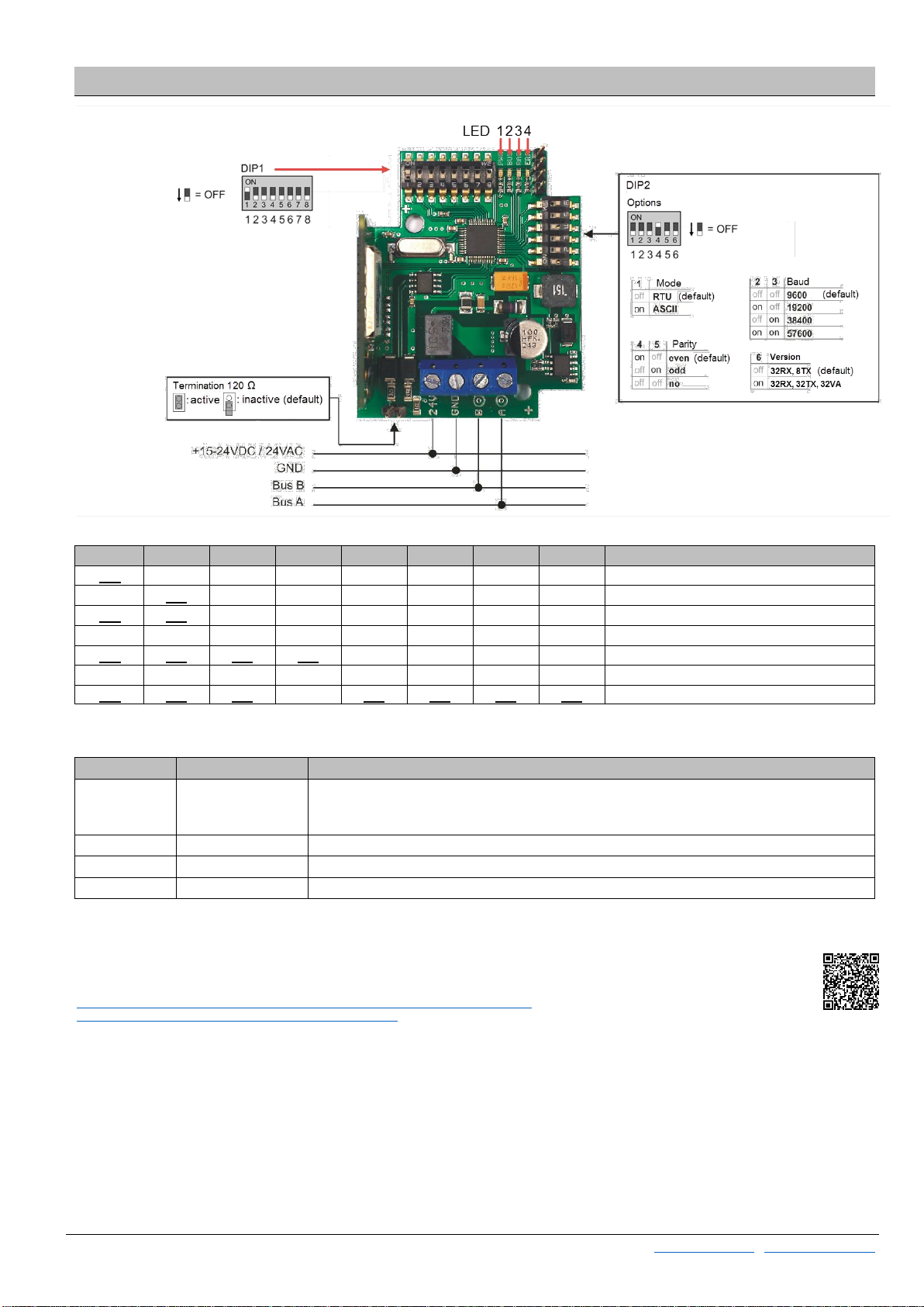
Configuration
DIP 1
DIP 1.1 DIP 1.2 DIP 1.3 DIP 1.4 DIP 1.5 DIP 1.6 DIP 1.7 DIP 1.8 Address
ON OFF OFF OFF OFF OFF OFF OFF 1 (default)
OFF ON OFF OFF OFF OFF OFF OFF 2
ON ON OFF OFF OFF OFF OFF OFF 3
………………………
ON ON ON ON OFF OFF OFF OFF 15
………………………
ON ON ON OFF ON ON ON ON 247
LED
Designation Description
LED 1 PWR Power supply OK
LED permanently ON →compatibility mode ON (DIP 2.6 = OFF | 32RX, 8TX)
LED flashes →compatibility mode OFF (DIP 2.6 = ON | 32RX, 32TX, 32VA)
LED 2 BUS Indicator RS485 traffic
LED 3 RAD Indicator EnOcean traffic
LED 4 ERR Indicator for error notification
When using ASCII mode, the parity must be set to EVEN or ODD. „No Parity“ (no) is not available in ASCII mode.
The configuration software and more information about the parameter of the STC65-RS485 Modbus,
please download from the following link.
http://www.thermokon.de/download-archive/EasySens%20-%20Empf%C3%A4nger/Gateways/
STC65-RS485%20MODBUS/Software/STC65-RS485_Modbus.zip

Page 4 / 4 Issue Date: 18.01.2016
Thermokon Sensortechnik GmbH, Platanenweg 1, 35756 Mittenaar, Germany · tel: +49 2778 6960-0 · fax: -400 · www.thermokon.de · email@thermokon.de
STC65-RS485_Modbus_Datasheet_en-us.docx © 2016
Installation
Radio sensors send time- or event-controlled telegrams to the receiver. The receiver verifies the incoming telegrams and output
them directly via their interface. Each telegram allows a precise allocation and consists of the format: type of the telegram, data,
sender-ID 32bit.
In order to assure a correct evaluation of the measuring values by the receiver, it is necessary to have the devices learned by the
receiver. This is done automatically by means of a “learn button” at the sensor or manually by input of the 32bit sensor ID and a
special “learning procedure” between sender and receiver. The respective details are described in the corresponding software
documentation of the receiver.
*depending on the respective receiver type
Dimensions (in.)
Accessories
Antenna extension 33ft. Item No. 257206
Antenna extension 66ft. Item No. 257213
Antenna holder form L, 7.09 x 7.09in. Item No. 255097
Rawl plugs and screws Item No. 102209
Table of contents
Other Thermokon Accessories manuals

Popular Accessories manuals by other brands


Baumer
Baumer OADM 20I6541/S14F quick start guide

Cranborne Audio
Cranborne Audio 500R8 user manual

Abicor Binzel
Abicor Binzel TH6D Instruction leaflet
Independence
Independence Logo! Easy owner's manual

CMP
CMP DEL UV SPA INSTALLATION INSTRUCTIONS & PRODUCT MANUAL

Pepperl+Fuchs
Pepperl+Fuchs UC2000-L2-E6-V15-Y277310 manual


