6
4. Operating Instructions
4.1 Operating the NL-33
• Switch on the press by pressing the power switch located at the rear.
• Set the desired temperature according to the chosen type of transfer
• Set the desired time according to the chosen type of transfer
• Set the desired pressure by turning the pressure adjustment knob in the middle, below
the display. Turn left to decrease the heat sealing pressure, turn right to increase the
heat sealing pressure.
• Check the set pressure on the manometer which is mounted to the left of the pressure
adjustment knob.
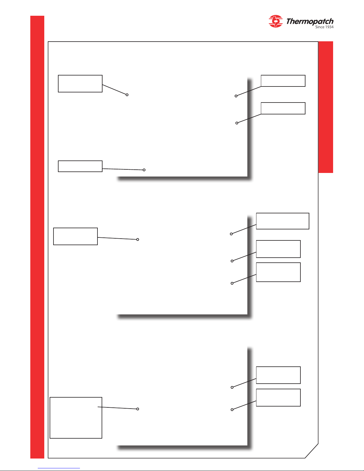
4.2 Operating the control panel
The settings for temperature and time are displayed on the control panel.
4.2.1 Setting the temperature and the heat sealing time
a) Temperature
• Press the temperature symbol on the screen. Press - or + and hold for decreasing or in-
creasing the setting.
• Press the 'WELCOME' key to conrm and storing of the setting.
• You can also choose to make use of presets by means of the arrow keys on the screen.
b) Time
• Press on one of the two elds for time setting on the screen. Each side, left or right, has
its own setting. Press - or + and hold for decreasing or increasing the setting.
• Press the 'WELCOME' key to conrm and storing of the setting.
• You can also choose to make use of presets by means of the arrow keys on the screen.
c) Pressure
• Use the grey pressure adjustment knob in the middle, under the display. The actual
pressure setting is shown on the manometer, placed to its left.
• Pull the knob outwards to unlock and turn left for a decrease in pressur and right for an
increased pressure.
• Push the knob back into place again to lock it.
d) Adjusting the swing speed of the press
• Please contact your supplier to adjust this setting.