12V Marine Air Conditioning
10. Electrical Installation
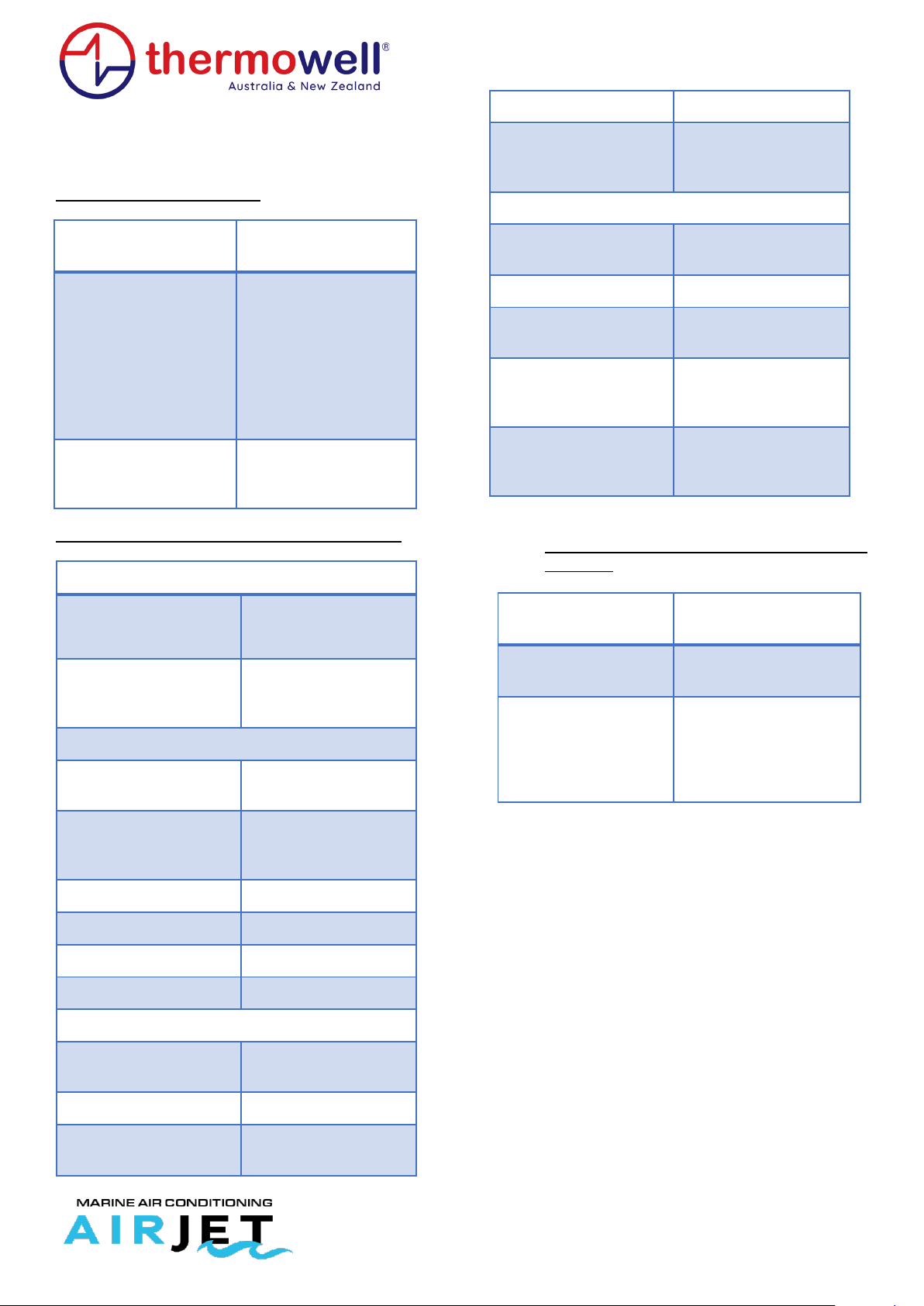
10.1. Cables
Main’s power must be supplied by means of a fuse or a switch with
a corresponding rating. To make the following connections, use PVC
insulated three-core, four-core or multi-core cables with copper
conductors laid in accordance with the established conditions. The
dimensions of the cables should be selected for 100% of the rated
currents of the consumers. This table is a simple reference for
correct cable sizing.
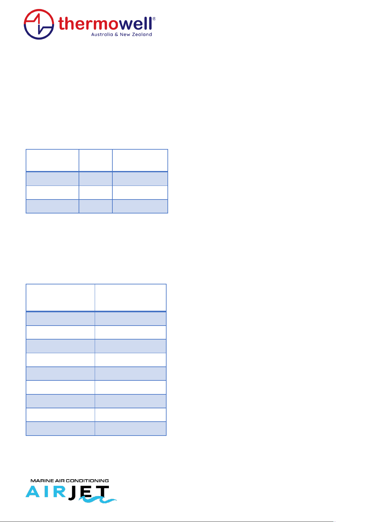
CURRENT
The flow rates shown in the above table have been defined at a
conventional ambient temperature of 30°C (it is assumed that the
temperature may occasionally reach 35°C). If the ambient
temperature is lower than the conventional temperature, the flow
rate increases, but if the temperature increases, the flow rate
decreases. The following table shows these room temperature
correction coefficients.
for flow rate
,
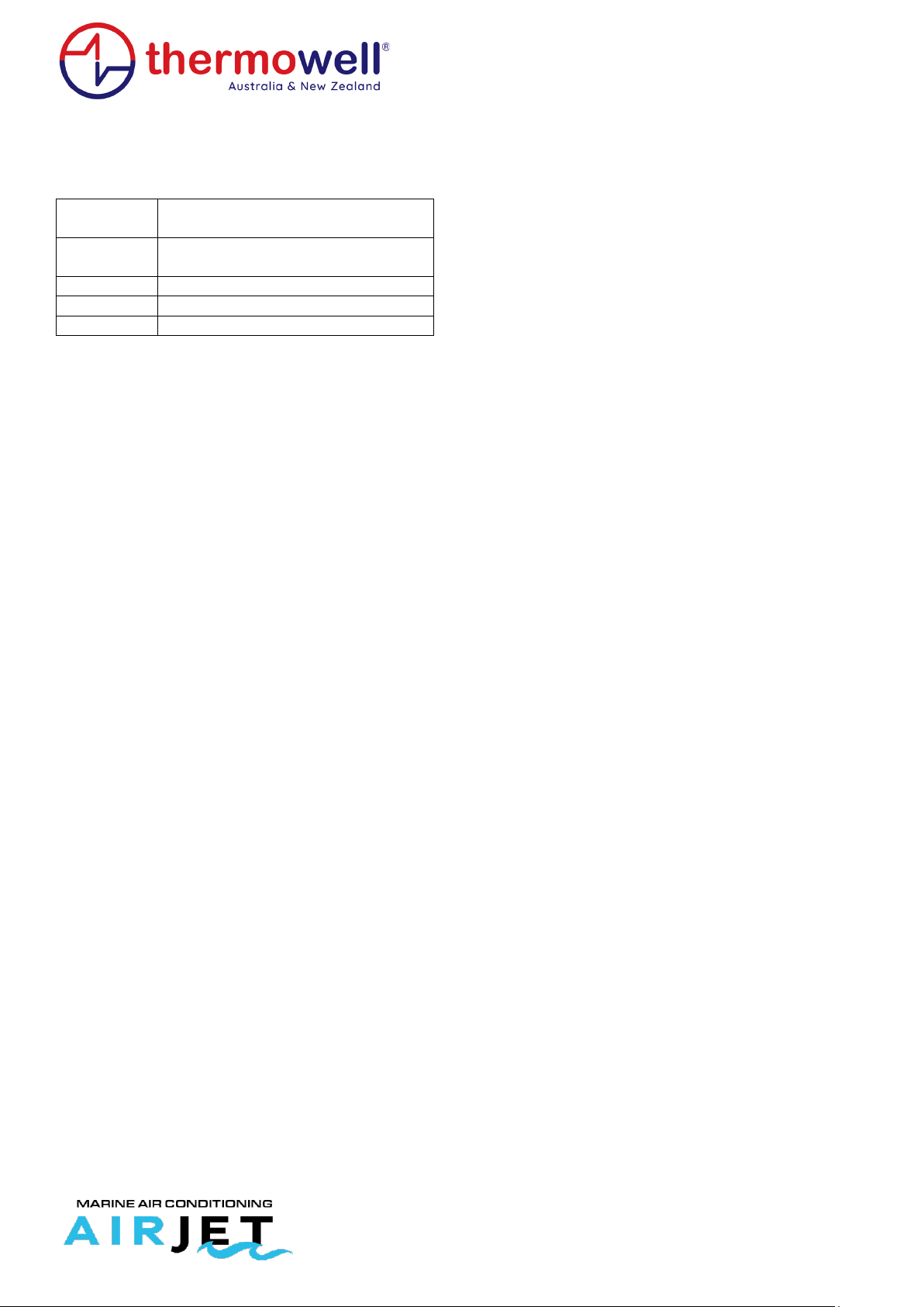
11. Regulatory references
The main reference standards are listed below:
UNI EN 14511-1:2018 Air conditioners, liquid chillers, and heat
pumps with electrically driven compressors for space heating and
cooling, and process cycle chillers with electrically driven
compressors - Part 1: Terms and definitions
UNI EN 14511-2:2018 Air conditioners, liquid chillers, and heat
pumps with electrically driven compressors for space heating and
cooling, and process cycle chillers with electrically driven
compressors - Part 2: Test conditions
UNI EN 14511-3:2018 Air conditioners, liquid chillers, and heat
pumps with electrically driven compressors for space heating and
cooling, and process cycle chillers with electrically driven
compressors - Part 3: Test methods
UNI EN 14511-4:2018 Air conditioners, liquid chillers, and heat
pumps with electrically driven compressors for space heating and
cooling, and process cycle chillers with electrically driven
compressors - Part 4: Requirements
UNI EN 378-1:2017 Refrigeration systems and heat pumps - Safety
and environmental requirements - Part 1: Basic requirements,
definitions, classification, and selection criteria
UNI EN 378-2:2017 Refrigerating systems and heat pumps - Safety
and environmental requirements - Part 2: Design, construction,
testing, marking and documentation
UNI EN 378-3:2017 Refrigerating systems and heat pumps - Safety
and environmental requirements - Part 3: Installation site and
personal protection
UNI EN 378-4:2017 refrigerating systems and heat pumps - Safety
and environmental requirements - Part 4: Operation, maintenance,
repair, and recovery
UNI EN 1736:2009 Refrigeration plants and heat pumps - Flexible
piping elements, vibration isolators, expansion joints and non-
metallic pipes - Requirements, design, and installation
UNI EN 1861:2000 Refrigeration systems and heat pumps - System
flow diagrams and diagrams of piping and instrumentation - Layout
and symbols
UNI EN 12178:2017 Refrigerating systems and heat pumps - Liquid
level indicators - Requirements, testing and marking
UNI EN 12263:2000 Refrigerating systems and heat pumps - Safety
switching devices for pressure limitation - Requirements and tests
UNI EN 12284:2004 Refrigerating systems and heat pumps - Valves
- Requirements, testing and marking
UNI EN 12828:2014 Heating systems in buildings - Design of water
heating systems
UNI EN 12831-1:2018 Energy performance of buildings - Method for
calculating design heat load - Part 1: Heat load for space heating,
Module M3-3
UNI EN 13136:2019 Refrigeration plants and heat pumps - Pressure
relief devices and associated piping - Calculation methods