TheSunPays BALI48 User manual

Lithium-ion Battery Pack
Model: BALI48
User manual
Version: 1.4
Please comply with all warnings and operating
instructions in this manual strictly. Save this manual
properly and read carefully the following instructions
before installing the unit. Do not operate this unit
before reading through all safety information and
operating instructions carefully.
1. When in use
High voltage:
Beware of high voltage power supply. If wet or conductive material meets a high voltage power supply,
directly or indirectly, it can result in an electric shock that can be fatal.
Use correct tools:
When working with high voltage and AC power, be sure that the correct tools are used.
Static‐free
Static electricity would damage veneer on the electrostatic sensitive components. before touching the
plug, isolate, circuit board or chips, be sure to use correct electrostatic prevention measures.
Safety Precaution

3
Disconnect the power supply in operation:
While operating the power supply, you must first cut off power supply, power operation is prohibited.
DC short circuit dangerous:
Power system provides dc regulated power supply. DC short circuit could cause fatal damage to the
equipment.
2.While charging
CAUTION
The temperature range over which the battery can be charged is 0°C to 45°C. Charging the battery at
temperatures outside of this range may cause the battery to become hot or to break. Charging the
battery outside of this temperature range may also harm the performance of the battery or reduce the
battery’s life expectancy.
3.When discharging the battery
CAUTION
The temperature range over which the battery can be discharged is -20°C to 60°C. Use of the battery
outside of this temperature range may damage the performance of the battery or may reduce its life
expectancy.
DANGER
Do not discharge the battery using any device except for the specified device. When the battery is used
in devices aside from the specified device it may damage the performance of the battery or reduce its
life expectancy, and if the device causes an abnormal current to flow, it may cause the battery to
become hot and cause serious injury.

4
Table of Contents
1. When in use......................................................................................................................2
2. While charging .................................................................................................................3
3. When discharging the battery .........................................................................................3
4 Parameters of Battery .........................................................................................................5
4-1 Parameters of Battery Pack ................................................................................................5
4.2 Technical Parameters of Battery Management System (BMS) ................................................6
4.3 Dry contact description .................................................................................................... 16
5. Basic Block Diagram ......................................................................................................... 17
6. Installation and Operation............................................................................................... 17
6-1. Unpacking and Inspection ............................................................................................... 17
6-2. Panel View..................................................................................................................... 18
6-3. Single battery Installation ............................................................................................... 19
6-4. Software Installation....................................................................................................... 19
6-5. Installation of Battery in Parallel ...................................................................................... 20
6-6 Installation Precautions.................................................................................................... 20
6-7 Operation Instruction for Installation................................................................................. 21
6-8. Circuit breaker of battery circuit is set to OFF, connect it to switch power supply, and output
voltage of switch power supply is set to 52.5-54V/56-57.6V, current set to 0.2C; after all settings
done, switch the circuit breaker ON. ....................................................................................... 27
6-9. Communication of battery............................................................................................... 27
6-10. Monitor pc Software interface........................................................................................ 29
6-11 Upper machine instructions ............................................................................................ 29
6-12 Address Switch function (Only in Parallel) ........................................................................ 33
6-13 Communication Function ................................................................................................ 34
7. BMS Operations ................................................................................................................ 35
7-2. Buzzer Operation (Optional) ............................................................................................ 36
7-3. Reset key function.......................................................................................................... 36

5
8. Troubleshooting................................................................................................................ 36
9. Storage and Maintenance ................................................................................................ 37
9-1. Storage ......................................................................................................................... 37
9-2. Maintenance .................................................................................................................. 37
10. Product Responsibilities and Consulting ............................................................................. 38
4 Parameters of Battery
4-1 Parameters of Battery Pack
Model of battery pack
BALI48
Nominal voltage
48V
Rated capacity
Above 100AH
Rated reserved energy
4800WH
Maximum charging current
1C(100A)
Total charging cut-off voltage
54.75V
Floating charge voltage
52.5±0.5V
Cut-off voltage of charging monomer
3.65V
Standard discharging current
0.2C (20A)
Maximum continuous discharging current
1C (100A)
Internal Resistance
≤30mΩ

6
Charging temperature range
0℃~45℃
Discharging temperature range
-20℃~60℃
Differential pressure at the discharging end
(2.5V for monomer)
≤300mV
Differential pressure at the charging end
(3.65V for monomer)
≤300mV
Dimension (W×D×H)
442*400*221mm
(excluding hanger and amphenol connector)
Weight
62kg
Gravimetric specific energy
112WH/Kg
Compound mode
15 Strings
4.2 Technical Parameters of Battery Management System (BMS)
Function name
Item list
Set value
Setting range
Monomer voltage
alarm
Overvoltage alarm
voltage
3,600±20mV
Alarm value of monomer undervoltage
to 4,500mV
Undervoltage alarm
voltage
2,800±50mV
1,000mV to alarm value of monomer
overvoltage
Monomer
overvoltage protection
Overvoltage
protection voltage
3,700±20mV
Recovery value of monomer
overvoltage
to
4,500mV

7
Overvoltage
recovery voltage
3,380±20mV
Recovery value of monomer
undervoltage to protection value of
monomer overvoltage
Overvoltage
recovery conditions
1. When the monomer voltage is lower than the
recovery point, automatically recover charging.
2. When the monomer voltage is lower than the
protection point and the capacity is ≤95%
(regular charging conditions: Charging once per
day), recover charging.
Undervoltage
protection voltage
2,500±50mV
1,000mV to
Recovery value of monomer
undervoltage
Monomer
undervoltage
protection
Undervoltage
recovery voltage
2,900±50mV
Protection value of monomer
undervoltage to
Recovery value of monomer
overvoltage
Undervoltage
recovery conditions
The valid charging current is detected, and the voltage
is higher than the recovery point.
Alarm of total voltage
of battery
Overvoltage alarm
voltage
54.0±0.3V
Alarm value of total voltage
undervoltage to 65V
Undervoltage alarm
voltage
42.0±0.5V
20V to alarm value of total voltage
overvoltage
Battery overvoltage
protection
Overvoltage
protection voltage
55.5±0.3V
Recovery value of total voltage
overvoltage to 65V
Overvoltage
recovery voltage
50.2±0.3V
Recovery value of total voltage
undervoltage to
Protection value of total voltage
overvoltage

8
Overvoltage
recovery conditions
1. When the total voltage is lower than the
recovery point, automatically recover charging.
2. When the total voltage is lower than the
protection point and the capacity is ≤95%
(regularly charging conditions: Charging once
per day), recover charging.
Battery undervoltage
protection
Undervoltage
protection voltage
37.5±0.5V
20V to
Recovery value of total voltage
undervoltage
Undervoltage
recovery voltage
43.5±0.5V
Protection value of total voltage
undervoltage
to
Recovery value of total
Undervoltage
recovery conditions
The valid charging current is detected, and the voltage
is higher than the recovery point.
Battery cell
temperature alarm
High temperature
alarm of battery
cell
55±3℃
Low temperature alarm
value of battery cell to 90℃
Low temperature
alarm of battery
cell
0±3℃
-40℃ to
High temperature alarm value of
battery cell
Charging high
temperature
protection
55±3℃
Recovery value of charging high
temperature to 90℃

9
No charging due to
temperature of the
battery cell
Charging high
temperature
recovery
50±3℃
Recovery value of charging low
temperature to
Protection value of charging high
temperature
Charging low
temperature
protection
-5±3℃
-40℃ to
Recovery value of charging low
temperature
Charging low
temperature
recovery
0±3℃
Protection value of charging low
temperature
to
Recovery value of charging high
temperature
Discharging high
temperature
protection
60±3℃
Recovery value of discharging high
temperature to
90℃
No discharging due to
temperature of the
battery cell
Discharging high
temperature
recovery
55±3℃
Recovery value of discharging low
temperature
to
Protection value of discharging high
temperature
Discharging low
temperature
protection
-20±3℃
-40℃ to Recovery value of discharging
low temperature

10
Discharging low
temperature
recovery
-15±3℃
Protection value of discharging low
temperature
to
Recovery value of discharging high
temperature
Ambient temperature
alarm
High ambient
temperature alarm
65±3℃
Alarm value of low ambient
temperature to
90℃
Low ambient
temperature alarm
-20±3℃
-40℃ to
Alarm value of high ambient
temperature
BMS temperature
protection
Mos-Over-
Temperature
Alarm (℃)
90±3℃
Recovery value of MOS high
temperature to
90℃
Mos-Over-
Temperature
Protection (℃)
110±3℃
-40℃ to
High temperature alarm value of
battery cell
Mos-Over-
Temperature
Protection Release
(℃)
85±3℃
Recovery value of charging low
temperature
to
Protection value of charging high
temperature

11
Ambient temperature
protection
High ambient
temperature
protection
70±3℃
Recovery value of high ambient
temperature
to
90℃
High ambient
temperature
recovery
50±3℃
Recovery value of low ambient
temperature to
Protection value of high ambient
temperature
Low ambient
temperature
protection
-20±3℃
-40℃ to
Recovery value of low ambient
temperature
Low ambient
temperature
recovery
0±3℃
Protection value of low ambient
temperature to Recovery value of high
ambient temperature
Charging overcurrent
alarm
Charging alarm
current
125±2A
3A to
Protection value of charging
overcurrent
Charging overcurrent
protection
Charging
protection current
130±2A
Alarm value of charging current
to
100A
Charging current
limiting function
Charging limiting
current
20A
It may be set to be 0, i.e. close the
charging current limiting function.

12
Discharging
overcurrent alarm
Discharging alarm
current
125±2A
Protection value of discharging
overcurrent
to
3A
Discharging
overcurrent protection
Discharging
protection current
130±2A
150A to
Alarm value of discharging current
Output short-circuit
protection
Short-circuit
protection locking
Continuous output short circuit and exceed the
overcurrent locking times
Short-circuit
unlocking
Continuous charger
Reverse polarity
protection
Yes
Automatic recovery of
overcurrent
60S
1 S to
60 S
Continuous
overcurrent locking
The overcurrent event with the time interval of no more than 5 min is called
continuous overcurrent.
3 times
One to
100 times
Equilibrium function of
battery cell
Charging
equilibrium of
battery cell
Cut-in conditions: State of valid charging current

13
Equilibrium cut-in
voltage
3,450mV
3,000mV to
4,500 mV
Voltage difference
of equilibrium cut-
in
30mV
Voltage difference value after
equilibrium
to
100mV
Voltage difference
after equilibrium
20mV
10mV to
Voltage difference value of equilibrium
cut-in
Equilibrium current
80mA
Equilibrium high
temperature
prohibition
50℃
Prohibition value of equilibrium low
temperature
to
70℃
Equilibrium low
temperature
prohibition
0 ℃
-20℃ to
Prohibition value of
equilibrium high temperature
Static equilibrium of
battery cell
Cut-in conditions: All non-discharging states
Estimate based on the voltage of the battery cell
After overvoltage protection, when the rest capacity of the battery is reduced
to
95% below or meets the regular charging conditions (charging once per day),
recover charging if the voltage is lower than the overvoltage protection setting

14
point.
Manual key setting
In the shutdown state of BMS, press the key for 1S for startup.
In the non-standby state of BMS, press the key for 3S for shutdown.
In the non-standby state of BMS, press the key for 10S, until all LEDs lights up
for reset.
BMS power
consumption
management
Maximum standby time: 4h (The AC does not discharge, without valid
discharging current).
Power consumption of
normal running
<30 mA
Static total power
consumption
Max 150uA
Type 100uA
Measure and monitor
the
State of Charge
≤ 5%
data record and
alarm history
≥ 1000 records
Display of SOC
Yes
Measure and monitor
accurancy
Module level: ≤ 0.5V of accuracy
Cell level: ≤ 0.05V of accuracy

15
Measure and monitor
the current of battery
module
Accuracy: ≤ 5%
Measure and monitor
the
temperature of battery
Accuracy: ≤ 3degC
Static total power
consumption
Max 150uA
Type 100uA
Push battery's
alarm via dry contact
Yes
Also push alarm even
when BMS is dead
Yes

16
4.3 Dry contact description
Functions and pin description:
•1, 2 Start on alarm
•3, 4 Start on battery power is low
DC circuit breaker
1,2,3,4

17
5. Basic Block Diagram
•There are Battery cells and BMS board inside, before connecting the terminal, please read the
diagram, and make sure the output is no short or other abnormal connection
.
Fig. 1 Battery Block Diagram
6. Installation and Operation
6-1. Unpacking and Inspection
Unpack the package and check the package contents. The shipping package contains:
●One Battery
●Two mounting brackets
●A small bag of screws and nuts
NOTE: Before installation, please inspect the unit. Be sure that nothing inside the package is damaged
during transportation. Do not turn on the unit and notify the carrier and dealer immediately if there is
any damage or lacking some parts. Please keep the original package in a safe place for future use.
18
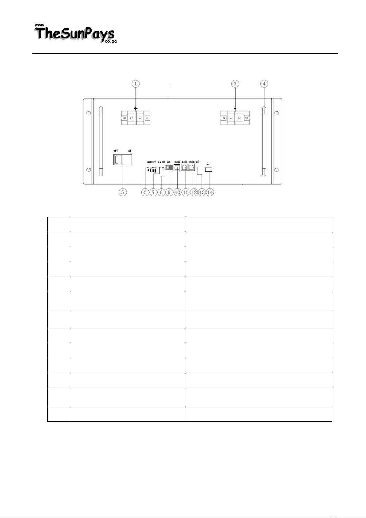
6-2. Panel View
No.
Description
Functional Description
1
Terminal as described on battery
+/-
3
Terminal as described on battery
+/-
5
Air switch
ON/OFF button
6
Display state information
Electricity volume indicator
7
Red- trouble-light on
Run indicator light blinking
8
Display state information
ALM alarm indicator light blinking
9
Display connection address
ADS Dialer
10
RS-232 connection port RS232
RS232 communication interface
11
RS-485connection port-B RS485
RS485 communication interface
12
RS-485connection port-A RS485
RS485 communication interface
13
Reset key
ON/OFF button
14
Dry contact
1,2 alarm 3,4 low power

19
6-3. Single battery Installation
Installation and wiring must be performed in accordance with the local electric laws/regulations and
execute the following instructions by professional personnel.
1) Make sure the mains wire and breakers in the building are following the standard of
rated capacity of the battery to avoid the hazards of electric shock or fire.
NOTE: Do not use the wall receptacle as the input power source for the battery, as its rated current
is less than the battery’s maximum input current. Otherwise the receptacle may be burned and
destroyed.
2) Switch off the mains switch in the building before installation.
3) Turn off all the connected devices before connecting to the battery.
4) Prepare wires based on the following table:
Table 1 Output cable thickness for single battery connection:
Model
Cables(AWG)
Cables(mm2)
<50Ah
8
6
50Ah
6
16
100Ah
4
25
NOTE 1: It is recommended to use suitable wire in above table or thicker for safety and efficiency.
5) Put the terminal block cover back to the front panel of the battery.
NOTE: Set the battery pack breaker in “OFF” position and then install the battery pack.
6-4. Software Installation
For optional computer system protection, install battery monitoring software to fully configure battery
shutdown and other setting value.

20
6-5. Installation of Battery in Parallel
6-6 Installation Precautions
1) Prior to installation, unpacking to check the quantity of the parts and battery appearance;
2) Install the hanger and handle and measure the battery voltage with a multimeter. The general
factory voltage of the battery is 51.5V-53.5V;
3) Prior to wiring, check the anode and cathode of the battery and the anode and cathode terminals
shall not be connected reversely;
4) During battery connection, please wear the protective gloves. When using such metal tools as
torque wrench, please perform insulating packaging for them and two end of the metal tools such
as torque wrench shall not contact the positive and negative terminals of the battery at the same
time to avoid battery short-circuit;
5) Before the battery is connected with the externally connected equipment, make the equipment in
a disconnected state, check whether the connecting polarity of the battery and total voltage are
correct, connect the battery anode with the equipment anode and battery cathode with the
equipment cathode and fix the connecting line;
6) During handling and placement, the battery must be handled gently. No dropping or impacting.
The battery shall not be thrown or beaten to avoid damaging the battery or resulting in potential
safety hazard;
Other manuals for BALI48
1
Table of contents
Other TheSunPays Batteries Pack manuals


