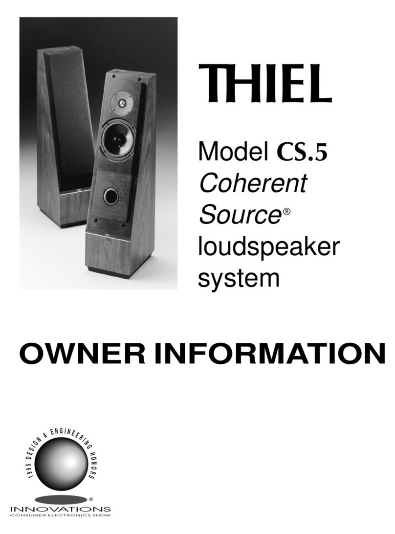
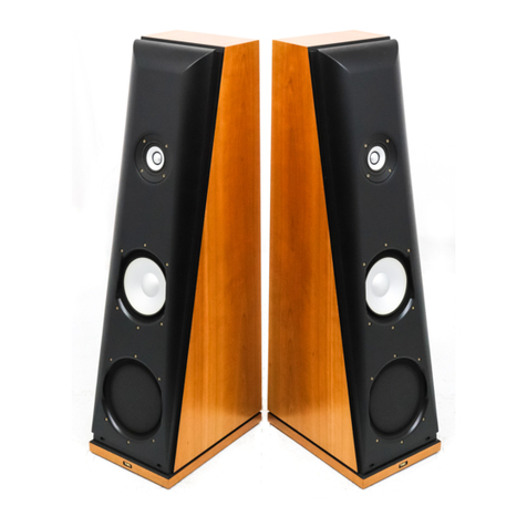
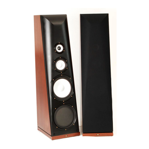
Thiel Coherent Source CS3.7 Technical manual

THIEL
Model CS3.7
Coherent
Source
®
loudspeaker
system
OWNER
INFORMATION
®

C
ongratulations on your purchase of
the THIEL CS3.7 Coherent Source ®
loudspeaker system. The CS3.7 is the
result of a long and dedicated effort to
provide the most accurate music
reproduction possible. We have used
only the highest quality components
and taken great care in the CS3.7’s
construction. Properly set up and used
with good associated equipment, the
CS3.7 will provide a great deal of
musical enjoyment for many years.
CONTENTS
Design philosophy..................................1
Positioning the speakers ....................... 2
Connecting the speakers ....................... 5
Leveling feet ......................................... 5
Break-in ................................................ 6
Associated equipment ........................... 6
Power requirements .............................. 6
Grille ..................................................... 7
Outrigger Base (optional) ..................... 7
Care....................................................... 7
Service....................................................7
Warranty ............................................... 9

DESIGN PHILOSOPHY
The CS3.7 is a precision
instrument designed to translate,
as accurately as possible,
electronic information into
musical sound. All our efforts
have been directed toward
achieving extremely faithful
translation of all tonal, spatial
and dynamic information
supplied by the amplifier.
The CS3.7 is not intended to
mask or mitigate shortcomings
of the recording or other
components in the music
playback system.
We believe this approach is
the only way to provide the
potential of experiencing all the
subtle aspects that help make
reproduced music a most
enjoyable human experience.
1
Jim Thiel,
Founder/Chief Design Engineer,
THIEL Audio

2
POSITIONING THE SPEAKERS
Because of their unipolar radiation pattern, the CS3.7s will provide good results when placed in a variety of room
locations. However, speaker placement will affect the accuracy of timbre, spatial performance, and bass perfor-
mance. Here are some guidelines to help you achieve the best sound from your speakers. (The pointed metal
stabilizer pins should not be installed until the final positioning has been determined.)
All aspects of speaker placement are dependent on the particulars of the room. Since every room is different, no
hard rules can be given, and experimentation is necessary to achieve the best results.
Distance from walls
The CS3.7s, like most speakers, sound best
if they are placed well away from all walls.
Such placement optimizes imaging charac-
teristics, and musical timbres are repro-
duced with the least coloration because the
initial sound coming from the speaker is
distinctly separated in time from the
secondary sound of wall reflections. If
reflections are heard too soon after the
primary sound, the brain tends to interpret
them as part of the initial sound, causing the
perceived timbre to be altered and the
spatial characteristics to be confused.
Figure 1 illustrates the problems caused
by early side wall reflections. When the
speaker is placed too close to side walls, the
difference in arrival times between the
primary sound waves and the reflected sound
waves is too short for the brain to discrimi-
nate between them.
Figure 2 illustrates the advantages of
placing the loudspeakers farther from side
walls. The arrival times of the primary,
forward radiating sound waves and the
secondary, reflected sound waves are well
separated, providing the proper delay needed
for faithful tonal and spatial reproduction.
There will also be a noticeable improve-
ment in openness when the speakers are even
two feet from the rear wall instead of one. If
possible, we prefer the speakers three feet or
more from the rear wall and five feet or more
from the side walls. Also, it is not desirable for large objects to be placed very near the speakers since these will also
be a source of unwanted early reflections that reduce imaging accuracy.
Figure 2. Optimum placement for reducing reflection problems
Direct sound
Reflected sound
Difference in arrival times
Figure 1. Early reflection problems caused by speakers placed
too close to side walls
Direct sound
Reflected sound
Difference in arrival times

3
Placement suggestions
Some people have restraints on speaker placement because
of room size, shape, or aesthetic considerations and cannot
meet one or more of the above placement recommenda-
tions. They should not be discouraged from investing in
CS3.7s. It is our opinion that due to their unipolar, point
source radiation pattern, their very even, wide dispersion,
and the co-axial mounting of the tweeter and midrange
drivers, the CS3.7s fare better under difficult circumstances
than most other high quality speaker systems. To help with
placement, the following suggestions are given as a starting
point for a variety of rooms.
Figure 3 shows an average size room. Generally, it is
best to start with short wall placement. This arrangement
provides sufficient space behind the speakers, allows the
listener to be far enough away from the speakers, and still
maintains some distance between the listening position and
the wall behind the listener. Since the speakers may be near
side walls in order to keep spacing between the speakers
wide, toeing-in the speakers is suggested.
Spacing
Because of their very wide, even dispersion of energy, the CS3.7s can usually be placed farther apart than most other
speakers. Optimum imaging is usually achieved when the speakers are almost as far apart as each speaker is from the
listener, although this will depend on the width of the room—narrow rooms require more narrow placement. If the
speakers are too far apart for the room, there will tend to be a “hole” in the middle of the soundstage; if they are too
close together, the image will be compressed and will not achieve optimum width.
Aiming
Depending on the room in which they are used, the CS3.7s can be aimed anywhere between straight ahead and
angled in so they point directly at the listener. Straight-ahead placement produces the widest, most natural
soundstage. However, if it is not possible to place the speakers the desired distance from side walls, a toed-in position
will reduce the strength of side wall reflections and, in these cases, provide a more focused spatial presentation.
Bass
In general, when a speaker is close to a wall, the bass response is stronger; placing a speaker in a corner will make it
even more so. The CS3.7s are designed to provide accurate bass when positioned away from all walls—the same
position that provides the best imaging.
Listener position
The CS3.7s provide broad dispersion of energy at all frequencies and therefore provide good results throughout a
large listening area. Best imaging is provided for a listener centered in front of the speakers. Optimum accuracy of
timbre and depth perspective is provided for a seated listener who is eight or more feet away from the speakers.
Figure 3. Average listening room
8'
2.5'
3'
10'
8'
3'
14'
2.5'
18'
8-10' Listening Distance

4
Some rooms, especially narrow ones, can
benefit from placing the speakers along the
long wall. Although space behind the
speaker and behind the listener is reduced,
this positioning increases the space
between the speakers without side wall
interference, and can improve overall
performance. Figure 4 shows the same
average size room as Figure 3, but with
long wall placement. The speakers should
be at least a foot from the rear wall, but the
amount of toe-in can be adjusted, along
with listener position, as well as the amount
of spacing between the speakers.
In a larger room, the optimum posi-
tioning suggestions on pages 2 and 3 are
easier to implement. Figure 5 shows one
set-up with the speakers five feet from the
side walls, three feet from the rear wall,
and the speakers aimed straight ahead. This
arrangement provides an ample amount of
space around the speakers to reduce
unwanted reflections and should give
excellent spatial performance and a very
“open” sound. Other placement options in
this room include: wider spacing between
the speakers, adding toe-in as the spacing
increases; increased space between the
speaker and the back wall to improve
imaging depth. Various listening position
distances can also be tried.
As mentioned at the beginning of the
positioning section, all rooms are different
and no hard rules can be given. Even rooms
with similar dimensions can have differ-
ences in wall, floor and ceiling construction
that greatly affect the sound. Also, “live”
rooms with hard surfaces, glass, and little
damping sound much different from “dead”
rooms with heavy carpet, drapes and plush
furniture. In other words—EXPERIMENT.
Figure 5. Large listening room speaker placement
Figure 4. Average listening room with long wall placement
8'
3'
5'
12'
8'
5'
3'
18'
25'
8-12' Listening Distance
1'
8'
1'
18'
14'
8-10 ' Listening Distance
10'
10' 4'
4'

CONNECTING THE SPEAKERS
The CS3.7’s input terminals are located on the
lower rear of the speaker cabinet. The CS3.7 uses
5-way binding posts that accept several types of
wire connections. Regardless of the type of wire
termination, make sure that all connections are
tight. The input terminals are designed to be easily
tightened by hand or a 1⁄2inch nut driver can be
used.
It is essential for proper performance that both
speakers in a stereo system be wired in the same
polarity. The speaker’s input terminals are color
coded to facilitate this. The wire connected to the red
ringed input terminal of each speaker should connect
to the respective positive (+) output terminals of the amplifier; the wire connected to the black ringed input terminals
should be connected to the respective negative (–) output terminals of the amplifier.
The speakers should be connected to the amplifier with high quality cable to ensure minimal loss of power and proper
control by the amplifier. If the speakers are being connected to a vacuum tube amplifier with various impedance taps,
the 4 ohm tap will usually give the best results.
STABILIZER FEET
The speakers should be positioned before the stabilizer feet are installed.
Speakers positioned on a soft or uneven surface are able to rock slightly and will vibrate
in reaction to forces the speaker generates to move the driver diaphragms. (Every action
has an equal and opposite reaction.) This motion slightly reduces the music’s clarity.
To eliminate this effect, the CS3.7s can be used with four stabilizer feet on uneven
surfaces or on carpeted floors to provide a more solid footing and allow the speaker to
couple more firmly to the floor. To install the feet:
• Position the speaker in the desired location.
• Tilt the speaker forward slightly so that the back of the speaker is a few inches off the
floor.
• Screw one foot, with the locking nut threaded all the way onto the foot, into each of the
two holes at the back corners of the speaker bottom. The pins should be screwed into the
speaker until there is about 1⁄4" of thread remaining visible.
• Let the back of the speaker down and then tilt the speaker backward slightly so that the
front is a few inches off the floor and install the two front feet.
• With all four feet installed, the height of each foot should be adjusted so that the speaker stands firmly on the
floor without wobbling. Then tighten the lock nuts by turning them so they are tight against the cabinet to secure the
feet to the cabinet
Please be cautioned that the stabilizer feet can dent hardwood floors and it is possible to mar the floor’s surface if
the speakers are moved with the feet in place.
5
Bottom rear cabinet view
Stabilizer Foot
lock nut

6
BREAK-IN
The CS3.7s, like most speakers, require a period of playing before they perform optimally. The time required depends
on how loudly the speakers are played; more time is required if played softly, less if played loudly. At least 50 hours at
moderately loud levels are required before the speaker is performing near optimum. You should notice even more
improvement after 100 hours of playing.
ASSOCIATED EQUIPMENT
The CS3.7s are very high quality sound reproducers and will benefit from use with the finest associated equipment.
Because the CS3.7 is a 4 ohm speaker, an amplifier with high current capability is recommended. It is desirable that the
amplifier provide twice the power into a 4 ohm load as into an 8 ohm load. Since the CS3.7s are extremely accurate
transducers, they will reveal distortions generated anywhere in the system. Also, the quality of the interconnect and
speaker cables will significantly affect the performance of the system.
POWER REQUIREMENTS
It is important to have enough power to play at the level you desire without distortion. If you play the speakers more
loudly than the volume the amplifier can cleanly produce, the amplifier will produce overload (clipping) distortion. The
sound will become compressed, strained, and in extreme cases, obviously distorted. This distortion is actually non-
musical additional energy and since it is concentrated in the high frequency region where the speaker is least able to
handle it, tweeters can be damaged in extreme cases. If high sound levels are desired, the CS3.7’s are designed to be
used with amplifiers rated up to 600 watts per channel.
Keep in mind that sound quality is usually more important than sound quantity. There can be large differences in the
sonic performance of two amplifiers of equal power, and this is more important than large differences in power. Most
everyone will be happier with a 100 watt amplifier of high sonic quality than a 200 watt amplifier of mediocre sonic
quality. For this reason, we feel there is no substitute for listening in making your amplifier decision.
The question “how much power do I need?” does not have the simple answer most people expect because it is not
determined only by the loudspeaker’s efficiency, but also by the volume desired and the size of the room. If all three
factors are average, about 100 watts per channel is required. Each factor can raise or lower this amount by about three
times.
1) Usually, people who “don’t like music loud” can decrease their power to about one-half. Also, people who like
music loud should increase their power by 2 times or more. Most people fall within a normal range.
2) A speaker with a low efficiency of 84dB/2.8 V-1-m will require twice the power of an average 87dB/2.8 V-1-m
speaker and one with a high rating of 90dB/2.8 V-1-m will require only half the power of an average speaker. The CS3.7
is of high efficiency (90dB) and therefore can work well with smaller amounts of power from a quality amplifier.
3) A small room will need less power for a given loudness level than a large room. A very small room of 1000 cu ft
(11' x 11' with an 8' ceiling) will require about half the power of an average size room. A large room of 6000 cu ft (20' x
30' with a 10' ceiling) will require twice the average power. If the listening room is connected to another room by a large
open area, the required power will increase, but not by the amount of the combined room volume. If the room has a
“dropped” ceiling with light panels, the ceiling will be almost transparent acoustically and the space above the ceiling
should be added. If the panels are heavy they will act as a more normal ceiling.
With all this in mind, a person who doesn’t like to play music very loudly and has a small room can get quality sound
with 50 watts or even less whereas a person who sometimes likes to play loudly and has a large room may need 400
watts or more.

7
GRILLE
The CS3.7 grille is attached magnetically to the front of the speaker. The grille is designed to not produce
diffraction so there is no sonic reason to remove it. If you do need to remove the grille, carefully pull the grille
frame away from the front of the speaker. When replacing the grille, line up the grille with the baffle’s inlay edges.
OPTIONAL OUTRIGGER BASE
The CS3.7s can be used with an optional Outrigger base (shown right). The
Outriggers attache to the bottom of the speaker cabinet with four mounting
bolts (provided with the Outrigger) screwed into the four threaded openings
normally used for the speaker’s stabilizer feet. Complete installation
instructions are included with the Outriggers.
CARE
The cabinets possess a high quality lacquer finish that is both beautiful and
durable. However, any wood finish can be damaged by excessive moisture,
dryness, or direct sunlight.
When cleaning your speakers, avoid using oils, waxes, or polishes that
contain silicone. We recommend Endust. Dusty grilles can be cleaned by
using the upholstery attachment of a vacuum cleaner.
SERVICE
If your speaker system requires service, contact your authorized THIEL
dealer. If you need to contact THIEL directly, service information and
technical support is available at (859) 254-9427, Monday-Friday, 8:30 a.m. -
dealer information and a “Frequently Asked Questions” section can be found
at our web site, www.thielaudio.com.
CS3.7 with optional
Outrigger Base

8
CS3.7 SPECIFICATIONS
Bandwidth (–3dB) 32 Hz-35 kHz
Amplitude Response 33Hz-22 kHz ±2 dB
Phase Response Minimum ±10°
Sensitivity 90 [email protected] V-1m
Impedance 4 ohms (2.8 ohms minimum)
Recommended Power 100-600 watts
Size (w x d x h) 12.5 x 21x 45 inches
32 x 53 x 114 cm
Weight 91 lbs/ 41.5 kg
The Following Noises Can Be Dangerous
Under Constant Exposure
90 Subway, motorcycle, truck traffic, lawn mower
100 Garbage truck, chain saw, pneumatic drill
120 Rock concert in front of speakers, thunderclap
140 Gunshot blast, jet plane
150 Rocket launching pad
Decibel
Level Example
30 Quiet library, soft whispers
40 Living room, refrigerator, bedroom away from
traffic
50 Light traffic, normal conversation, quiet office
60 Air conditioner at 20 feet, sewing machine
70 Vacuum cleaner, hair dryer, noisy restaurant
80 Average city traffic, garbage disposals, alarm
clock at two feet
We Want You Listening For A Lifetime
Used wisely, your new sound equipment will provide a lifetime of enjoyment. Since hearing damage from loud
noise is often undetectable until it is too late, THIE L and the Electronics Industries Manufacturers Association
recommend you avoid prolonged exposure to excessive noise. Depending on room size and amplifier power, some
home audio systems can reach sound pressure levels in excess of 95 decibels with peaks of over a 105 decibels. For
your protection, the list below identifies sound levels for various noises.
Information courtesy of the Deafness
Research Foundation and the EIA.

9
LIMITED WARRANTY
THIEL warrants every THIEL model CS3.7 system against defects in materials and workmanship to the original
owner for a period of ten years from the date of purchase. THIEL will, at no charge, replace any defective part and
make any repairs necessary to ensure its proper performance when the defective unit is returned to us postpaid.
This warranty does not cover damage due to accident or abuse and is void if the unit has been tampered with.
This warranty is automatic and no registration is required. This warranty gives you specific legal rights. You
may also have other rights which are particular to your state.
The following information is for your records.
Serial Numbers______________________________
Purchase Date_______________________________
Purchased From_____________________________
REGISTER YOUR 10 YEAR WARRANTY ONLINE AT
www.thielaudio.com/registrations/new

4/07
THIE L
1026 Nandino Boulevard, Lexington, Kentucky 40511-1207
04/07

THIEL Outriggers are used instead of normally mounted stabilizer feet to provide
greater stability. They are attached to the bottom of the speaker cabinets with
four mounting bolts screwed into the four threaded openings normally used for
the stabilizer feet. The 4 stabilizer feet shipped with the speaker are then used
as the feet of the outriggers.
Installing Outriggers
Place the speaker on its back with the bottom of the speaker propped an inch or more off the
ÁRRU,IVWDELOL]HUIHHWDUHLQVWDOOHGUHPRYHWKHP
Mount a long strut to the front of the speaker with the ends curving forward and the recesses
at the ends pointing downward by using two of the included bolts into the speaker’s front
VRFNHWV8VLQJWKHSURYLGHGKH[ZUHQFKWLJKWHQWKHEROWVZHOODERXWLQOEWDNLQJFDUH
QRWWRRYHUWLJKWHQ
8VLQJWZRRIWKHLQFOXGHGEROWVWRVHFXUHLWPRXQWDVKRUWVWUXWWRWKHUHDURIWKHVSHDNHUZLWK
the ends curving backward and the recesses at the ends pointing downward.
Remove the locknuts from the feet and store them. Thread the feet completely through the
threaded holes in the outrigger struts from the bottom. Install the caps over the exposed
threads on the top of the struts.
:LWKWKHVSHDNHUVWDQGLQJYHUWLFDOO\LQLWVÀQDOORFDWLRQORRVHQDOOIRXUFDSVDQGWKHQWKUHDG
RQHRUPRUHIHHWGRZQZDUGXQWLOWKHVSHDNHULVVLWWLQJÀUPO\RQWKHÁRRUDQGGRHVQRW
wobble when pushed slightly from any direction. Then tighten all four caps.
THIEL CS3.7 Outrigger
Installation Instructions
THIEL
1DQGLQR%RXOHYDUG/H[LQJWRQ.<7HOHSKRQH)D[
(PDLOPDLO#WKLHODXGLRFRPZZZWKLHODXGLRFRP
CS3.7 with outriggers installed
Locknut
Cap
Rear Strut
Front Strut
Strut Recess
Bolt
Foot
Questions? Contact THIEL’s service department
859-254-9247 M-F, 8:30 am- 5:00 pm ET.

Supplemental
Technical Information
for model
THIEL CS3.7
Coherent Source
®Loudspeaker
This paper contains only information specific to the CS3.7 speaker system.
It is intended to supplement the general technical information paper which
explains our engineering philosophy, goals and techniques.
This advance copy contains only technical information about the unique
midrange driver used in the CS3.7.
PRELIMINARY

NEW MIDRANGE DRIVER
The most important reason for the improved sonic
performance of the CS3.7 is its new midrange driver. This driver
was developed to solve two problems that otherwise exist in
midrange performance – diaphragm resonances and tweeter
interference. Before explaining the new solutions I will review the
problems that have been addressed by the new design.
Review of the Basic Problem
Drivers produce sound by moving their diaphragms in and out
following the waveform of the input signal. Ideally, the
diaphragm moves as a whole, every point moving the same as
every other point. This is called “piston” movement. All
diaphragms achieve piston operation at low frequencies but as the
frequency increases a point is reached where the movement of the
diaphragm “breaks-up”, with different parts of the diaphragm
moving independently of other parts. At these higher frequencies
the diaphragm is internally resonating, meaning that it is
oscillating of its own accord. These resonances cause the sonic
output of the driver to “ring” at these frequencies, producing sonic
output when it’s not supposed to. The resonances also cause some
frequencies to be exaggerated and others to be diminished,
changing the tonal character of the sounds being reproduced.
Previous state-of-the-art
The approach that THIEL has pursued to minimize the effects
of diaphragm breakup is to develop diaphragms that are stiff
enough to maintain piston operation throughout their primary
operating range. This is achieved by using aluminum as the
material, careful engineering of the diaphragm’s shape,
laminating the aluminum with styrene foam to stiffen and damp
the diaphragm and the use of larger diameter voice coils. These
techniques can result in diaphragms that have a much greater
range of frequencies reproduced under piston operation. An
example of such a driver is the THIEL CS6 midrange whose
response is shown here.
This
driver
exhibits
exceptionally
good
response,
with piston
operation
being
maintained to
beyond 5 kHz, almost an octave above its primary operating range
of 3 kHz. In addition, the resonant behavior that is exhibited at
high frequencies is much simpler than usual, basically consisting
of only one resonance below 10 kHz. This simplicity of resonant
behavior provides the advantage of making it feasible to
electrically correct and compensate for the dominant resonance.
The response exhibited after such electrical correction is graphed
here. This is
exceptionally
wide band
and
resonant-free
operation.
The Remainder
However, it is still true that what imperfections remain in the
midrange performance are primarily due to the residual effects of
the diaphragm resonances that do exist. And, therefore, to achieve
even better performance requires further improvement in
diaphragm behavior.
An Additional Problem
There is an additional problem concerning the midrange driver
that we wish to address. This second problem exists only as a by-
product of solving another problem (this type of situation is not
uncommon in loudspeaker design). The “other” problem in this
case is that of time coherence. Time coherence describes that all
component harmonics of every sound reach the listener’s ears at
the same time and is achieved by positioning the drivers so that
each is the same distance from the listener’s ears. THIEL uses two
techniques, singly or in combination, to achieve time coherence in
all our products. One technique is to mount the drivers on a sloping
baffle and adjust the angle of the slope and the driver spacing to
achieve coherence. This can work well for floor standing speakers,
especially at lower frequencies. But it cannot work for non floor
standing speakers where the location of the speaker is unknown,
and in any case the accuracy of the results at high frequencies
becomes somewhat dependant on the listener’s position. For this
reason, a better technique for time coherence at higher frequencies
is to mount the tweeter coincidently (both coaxially and
coplanarly) with the midrange driver. Such mounting ensures that
the sound from both drivers always reach the listener at exactly the
same time, regardless of where the speaker is placed or where the
listener is. Such mounting also completely eliminates any “lobing”
in the speaker’s radiation pattern.
Our “additional problem” is that such coincident mounting of
the tweeter in the center of the midrange driver alters the tweeter’s
output due to reflections and diffractions from the midrange
diaphragm. This effect is illustrated by the two graphs below. The
first shows the tweeter response as being extremely uniform and
free of resonances to beyond audibility. The second shows the
response when mounted in a normal midrange driver. The
detrimental alterations are clear. Even after electrical correction the
response leaves room for improvement.
Large distance from voice coil
to edge of diaphragm allows
diaphragm resonances at
frequencies lower than desirable.
Tweeter in the recessed shape
of the midrange cone causes
diffraction/ reflection problems.
voice coil
Midrange diaphragm
relies on resessed,
“cone” shape for strength.
Tweeter coaxially mounted in conventional midrange
10
100
5
0
-5
5
p
1kHz 10kHz
Response of CS6 midrange driver
10
100
5
0
-5
5
1kHz 10kHz
Response of CS6 midrange driver with electrical correction
100
5
0
-5
5
Amplitude — dB
1kHz 10kHz
Response of CS3.7 tweeter
100
5
0
-5
5
Amplitude — dB
1kHz 10kHz
Response of CS3.7 tweeter coaxially mounted in standard midrange

A Solution
What is needed to solve both these problems simultaneously
is a midrange diaphragm that is ten times as stiff per weight as the
previous extremely stiff composite diaphragm while also being
flat rather than cone shaped. But these requirements work against
each other. The flatter the diaphragm’s shape the weaker it
becomes. And even with a normal shape, how can we increase the
stiffness this dramatically? Even exotic materials like beryllium
are not nearly that stiff, even in the traditional cone shape.
The solution we developed relies on geometry rather than a
more exotic material to achieve both goals. There are several
elements to the design:
• A large voice
coil is used so that
its force is applied
at a point equally
spaced between the
diaphragm’s inner
and outer edges,
rather than at the
inner edge. This
reduces the
distance from the
driving point to the
diaphragm’s edge
and therefore
greatly increases
stiffness.
• Reliance on
the great stiffness in the circular direction of the voice coil
former’s cylindrical shape so that the diaphragm itself is only
required to provide stiffness in the radial direction. This allows
the diaphragm to be formed with shapes that greatly increase
strength in the direction from the center to the edge, even if
decreasing strength around the circumference.
• An undulating, radially ribbed contour is used for the
diaphragm which provides light weight and great stiffness in the
radial direction while still maintaining a basically flat shape.
CS3.7 midrange diaphragm
Results
The
top graph
above
shows the
response
of the new
midrange
driver. As
you can
see the
response
is very
uniform,
without resonant peaks, to beyond the range of audibility. This is
unprecedented high frequency performance, and in fact is better
and more resonant-free response than is exhibited by many
tweeters!
The next graph shows the response of the tweeter when
mounted in the center of the midrange. Here you can see that the
tweeter’s performance is extremely uniform. This would be great
performance even if not mounted in a midrange driver. When
comparing this response to that of the tweeter alone (a previous
graph) there is very little difference. Compared to the graph of the
response in a normal midrange, the large improvement is obvious.
Other Details
There are of course many other elements to a driver than its
diaphragm. Even with the two problems we have discussed solved,
there are other design elements that are required to provide clean,
dynamic and clear reproduction.
In order to provide very clear (low distortion) output all THIEL
drivers employ copper-stabilized, short coil motor systems that
produce only one-tenth the distortion of conventional motor
systems. The penalty of this approach is that a much larger magnet
is required to power the much longer magnetic gap. This creates a
greater difficulty with this driver because the voice coil diameter is
so large that the required magnet, which must be outside the coil,
would be larger than the whole driver! In addition, such a large
magnet would make it impossible to provide a good rear venting
path for the diaphragm. For these reasons the CS3.7 midrange is
powered by a neodymium rare earth magnet that is 10 times as
strong per size as a normal magnet. Although this is expensive, it
provides high efficiency with a large magnetic gap while allowing
excellent venting.
The driver also utilizes a custom, die-cast, eight-ribbed chassis
that mounts the motor system from the outside and also provides a
rigid mount for the tweeter.
Other details of the driver include a copper pole sleeve to
reduce coil inductance modulation, a dual surround suspension, and
an aluminum voice coil.
CS3.7 midrange diaphragm viewed edge-on from the center
Please see next page for photo of the complete driver
Small distance from
driving voice coil to edge
of diaphragm ensures freedom
from diaphragm resonances
to a very high frequency.
Tweeter in the same plane as the
flat midrange diaphragm eliminates
diffraction/ reflection problems.
voice coil
Midrange diaphragm uses
basically flat, “ribbed” shape
for radial strength and coil
former’s cylindrical shape
for circular strength.
Tweeter coaxially mounted in CS3.7 midrange
10
100
5
0
-5
5
1kHz 10kHz
Response of CS3.7 midrange driver
100
5
0
-5
5
1kHz 10kHz
esponse of CS3.7 tweeter mounted in CS3.7 midrange
Right: CS3.7 midrange parts, cw from left: Die-cast chassis, neodymium
magnet, large diameter voice coil, ribbed diaphragm, copper pole sleeve

THIEL CS3.7 midrange driver with coincidently mounted tweeter
(actual size)
THIEL • 1026 Nandino Boulevard • Lexington, Kentucky 40511 • USA • www.thielaudio.com
12/05


Other manuals for Coherent Source CS3.7
6
Table of contents
Other Thiel Speakers System manuals

Thiel
Thiel CS2.3 Technical manual

Thiel
Thiel CS1.5 Technical manual

Thiel
Thiel SCS4 Dimensions

Thiel
Thiel CS6 Technical manual

Thiel
Thiel CS.5 Technical manual

Thiel
Thiel CS 2 User manual

Thiel
Thiel Coherent Source CS2.7 Technical manual

Thiel
Thiel CS 5i User manual

Thiel
Thiel CS2.4 Technical manual

Thiel
Thiel CS6 Dimensions

Thiel
Thiel CS 7.2 User manual

Thiel
Thiel CS3.6 Technical manual

Thiel
Thiel Coherent Source SCS3 Technical manual

Thiel
Thiel Coherent Source CS1.6 Technical manual

Thiel
Thiel Model 03 User manual

Thiel
Thiel CS 1.2 User manual

Thiel
Thiel Model 01 User manual

Thiel
Thiel CS 3.5 User manual

Thiel
Thiel SCS4 Technical manual

Thiel
Thiel PCS User manual