Thiele Streamfeeder Value Series User manual

Manual
Value Series V-710DM

Part Number: 00900394
© 2010 Thiele Technologies, Inc. - Streamfeeder. All rights reserved.
No part of this publication may be reproduced, photocopied, stored on
a retrieval system, or transmitted without the express written consent of
Thiele Technologies, Inc. - Streamfeeder.
Thiele Technologies, Inc. - Streamfeeder
315 27th Avenue NE
Minneapolis, MN 55418 USA
Tel:(763) 502-0000
Fax:(763) 502-0100
e-Mail: service@streamfeeder.com
Web: www.streamfeeder.com
Printed in the USA.

i
Value SerieS V-710DM Manual
Contents
Safety Information ........................................................ii
Specications ..............................................................iv
Section 1: About the Machine .......................................................1
Section2: InstallingtheMachine ..................................................4
Section3: PreparingforOperation .............................................18
Section4: HowtoOperate ...........................................................29
Section5: OperationalTroubleshooting ....................................32
Section6: InspectionandCare ...................................................34
Section7: MechanicalComponents ...........................................40
Section8: ElectricalComponents...............................................54
Section9: TechnicalTroubleshooting ........................................58
ii Value SerieS V-710DM Manual
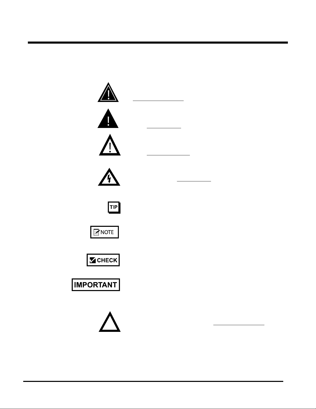
Message
Conventions
DANGER signies an action or specic equipment area that can result
in serious injury or death if proper precautions are not taken.
WARNING signies an action or specic equipment area that can
result in personal injury if proper precautions are not taken.
CAUTION signies an action or specic equipment area that can
result in equipment damage if proper precautions are not taken.
ELECTRICAL DANGER signies an action or specic equipment
area that can result in personal injury or death from an electrical haz-
ard if proper precautions are not taken.
TIP signies information that is provided to help minimize problems
in the installation or operation of the feeder.
NOTE provides useful additional information that the installer or
operator should be aware of to perform a certain task.
CHECK signies an action that should be reviewed by the operator
before proceeding.
IMPORTANT alerts the installer or operator to actions that can poten-
tially lead to problems or equipment damage if instructions are not
followed properly.
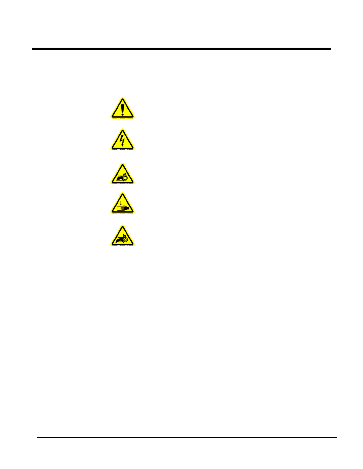
WARNING LABELS afxed to this product signify an action or spe-
cic equipment area that can result in serious injury or death if proper
precautions are not taken.
Before You Begin
iii
Value SerieS V-710DM Manual
Message
Conventions
Before You Begin
Avoid injury. Do not reach around guards.
Hazardous voltage. Contact will cause electric shock or burn. Turn off
and lock out power before servicing.
Moving parts can crush and cut. Keep guards in place. Lock out power
before servicing.
Pinch point. Keep hands and ngers clear.
Moving parts can crush and cut. Keep guards in place. Lock out power
before servicing.

iv Value SerieS V-710DM Manual
Maximum Product Size: ......................... 12 W x 12 L in (305 x 305 mm)*
Minimum Product Size: ........................ 3.75 W x 3.75 L in (95 x 95 mm)
Optional: ...................................................... 2.5 W x 2.5 L in (63 x 63 mm)
Min/Max Product Thickness: ........................ .003-.75 in (.076-19.1 mm)
Belt Speed: ................................................ 4000 in/min (101,600 mm/min)
Electrical Requirements: ................................... 115/230vac, 50/60Hz, 3A
Weight: ............................................................................... 41 lbs. (18.6kg)
*Optional product size available
speCifiCations

v
Value SerieS V-710DM Manual
1Value SerieS V-710DM Manual
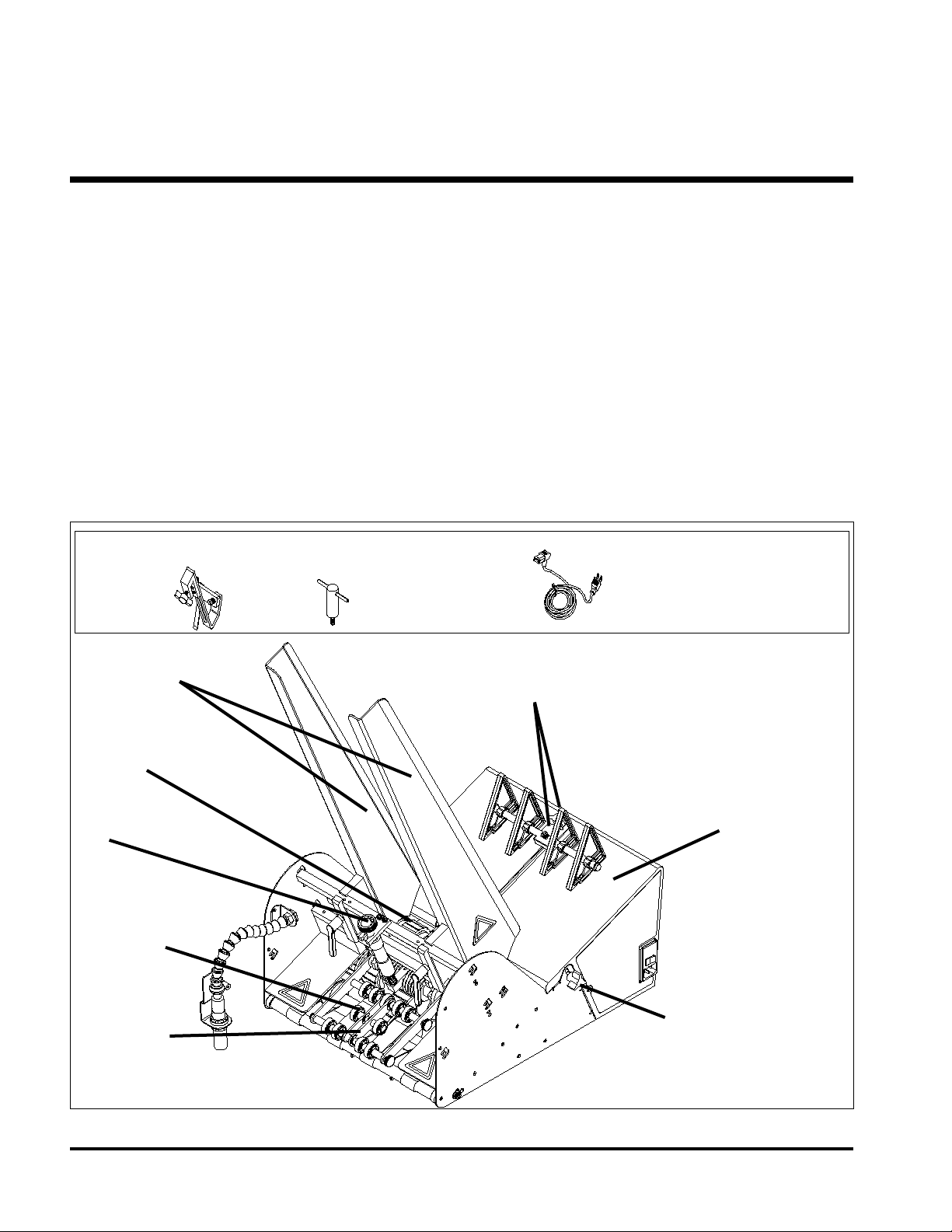
Back Wedge and Adjustments
Standard O-Ring
Gate
Table Top
Feed Belts
Hold-Down
Assembly
Discharge
Belts Raised Feed Belts
Adjustment
Side Guides
1About the Machine
The V-710DM Universal Friction Feeder is designed for reliability,
exibility, and ease of use with a variety of host systems. Included are
such applications as vacuum and non-vacuum bases and gripper-arm
inserters. All parts required for setup, loading, feeding, sensing and
easy operator control are combined into one compact unit.
Review the main assemblies in Figure 1-1 to become familiar with
names and locations of feeder parts and adjustments. This will help to
prepare you for initial setup. Descriptions are found in Table 1-1.
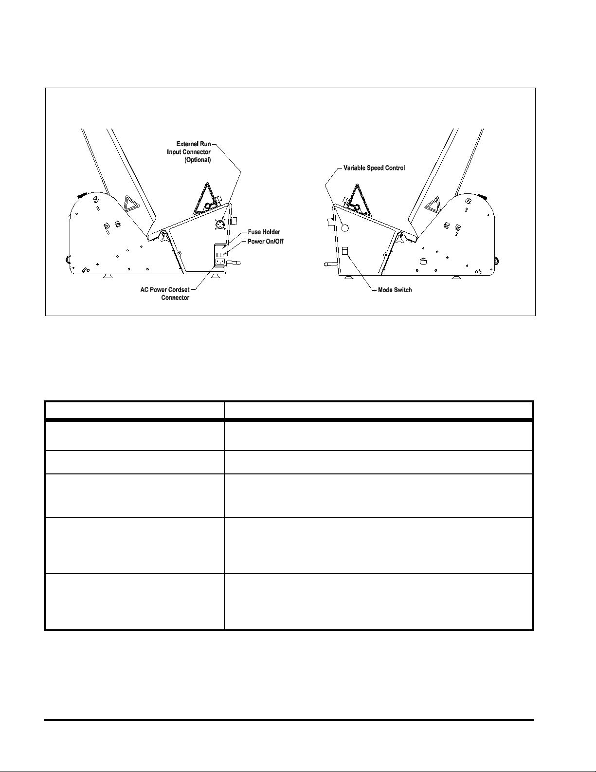
Review the control panel components in Figure 1-2 to become fa-
miliar with names and locations of specic connectors, switches, and
controls. This will help to prepare you for installation and operation.
Descriptions are found in Table 1-2.
AC Power
Cord
(2)
Hold-Down Spring
Assemblies
(2)
T-Handle Screws
with (4) #8 Flat
Washers
Features
Main Assemblies
Loose Parts Supplied Not Shown:
•SideGuides(2)
•SupportPedestal
Figure 1-1. Main Assemblies of the V-710DM Universal Friction Feeder

2
Value SerieS V-710DM Manual
Table 1-1. Main Assemblies Feature Descriptions
Feature Description
Gate assembly and adjustment Mounted on a gate bracket assembly above the feed belts, this device
provides a curvature to help preshingle stacked material. When properly
adjusted, a clearance is created to help singulate and feed material.
(Note: For multiple page material, a 1 to 1.5 maximum thickness is
typical.)
Table top Used to support the back wedge.
Raised feed belts adjustment Located on each side of the feeder, these adjustment knobs allow you to
raise the rear feed belts above the table top to achieve optimum contact
with material.
Side guides (adjustable) Holds a stack of material to be fed and helps keep it straight for proper
entry through the gate assembly area.
Back wedge and adjustments Lifts the material to keep it off the table top, reduces excessive contact
with the feed belts, and helps push the material against the curvature of
the gate assembly. To achieve proper lift, adjustment wing-nut allows you
to slide the wedge to various positions and angles.
Photosensorandexibleextension Also called a sheet-detect photo sensor, it "looks" for the leading edge of
the material to stop the feeder. For optimum setting, a exible extension
allows you to adjust for distance and perpendicular angle to material.
(Note: Sensor is used for gripper-arm inserter applications only.)
Feed belts and discharge belts Feed Belts: Provide the friction and motion necessary to pull individual
material from the bottom of the stack and through the gate assembly
area. Discharge Belts: Combined with the top roller hold-down assembly,
provides the friction and motion necessary to transport material away from
the gate assembly area.
Top roller hold-down assembly Provides the friction and motion necessary to pull materials away from the
gate assembly. Positioned above discharge belts.
AC power cord, 8 ft. (2.44 m) IEC320 removal three-prong. Shipped loose.
Discharge safety shields Provides a residual risk protection to operator when feeder is running.
Support pedestal Supports part of feeder that extends over the inserter's back deck plate.
Includes built-in height adjustment. (Note: Not used on vacuum base
applications.)
LOOSE PARTS
Hold-down spring assemblies (Note: For inserter applications.) As a piece of material exits the feeder
gate assembly area, these two hold-down spring assemblies help keep it
aligned and in proper position for the gripper jaw. Mounted on inserter.
T-handle screw assemblies (Note: For inserter applications only.) These two hand-tightening screws
secure the feeder to the inserter back deck plate. Fastened to underside
of feeder.
3Value SerieS V-710DM Manual
Feature Description
AC power cordset connector Cordset plugs into this IEC320 connector to provide feeder with power
from a grounded/fused outlet.
Power On/Off Toggles AC power On or Off.
Fuse holder Contains two replaceable GMD3, 3-Amp, 5-mm fuses. IMPORTANT:
Always make sure power module is replaced exactly as removed. Failure
to follow this caution will result in damaged electrical parts.
Variable speed control This dial switch (labeled Speed) allows the feeder speed to be
synchronized with an inserter, vacuum or non-vacuum base. Turning
counterclockwise decreases speed; clockwise increases speed. (Note:
Feeder motor stops if turned completely counterclockwise.)
Figure 1-2. Control Panel Components (Left and Right Side Views)
Control Panel Components
Table 1-2. Control Panel Feature Descriptions
Drycontactexternalruninput
connector and mode switch (optional)
This interface allows for the electrical integration into vacuum type bases for
integrated start/stop control.
Dry Contact
(Optional w/External Run)

4
Value SerieS V-710DM Manual
2Installing the Machine
When performing initial installation, always
make sure you turn Off the main power
switch and disconnect all equipment from the
electrical power source. Failure to do so can
expose you to a potential startup and moving
parts which can cause serious injury.
Do not attempt feeder installation while
the feeder and machine of application are
running. Failure to do so can expose you to
moving parts which can cause serious injury.
Do not wear loose clothing when operating the
feeder.
Avoid turning on the feeder or making initial
adjustments until all parts are secured. Failure
to do so can cause damage to equipment.
This section provides information on how to the install the V-710DM
Universal Friction Feeder in the following application environments:
• Vacuum base installation (2A)
• Inserter installation (2B)
Information for a particular application typically includes procedures
for basic parts removal, feeder mounting and alignment, and cable
connections for power and control interface. Information that relates
to specic adjustments you must make to feeder prior to startup and
operation is found in Section 3, Preparing for Operation.
2A:
Vacuum Base
Installation of the V-710DM Universal Friction Feeder onto various
types of vacuum and non-vacuum bases is a relatively simple proce-
dure. Several minor modications to the vacuum base are required
prior to mounting and aligning the feeder.
To install the feeder onto a vacuum base, perform the following steps:
1: Repositioning front side guides
2: Removing back jogging plate/back hopper guide
3: Raising hopping rollers
4: Disabling the shuttle
5: Initial positioning of feeder
6: Providing AC power to feeder
7: Checking material discharge from feeder
8: Miscellaneous feeder adjustments
5Value SerieS V-710DM Manual
1. Loosen locking knobs at both side guides (Figure 2-1).
2. Slide each side guide to the outermost position. Do not lock in
place.
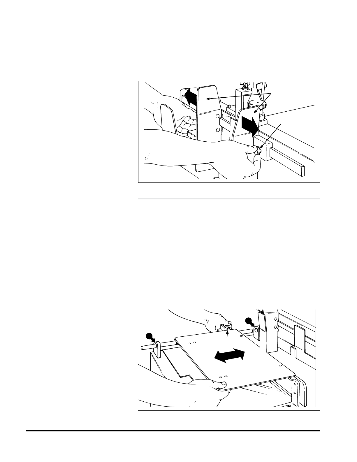
1. Loosen each of the setscrews at the two shaft housing assem-
blies A and B (Figure 2-2).
2. Slide shaft end closest to the vacuum base gate out of housing
A (with jogging plate/hopper guides still attached). Slide shaft
back far enough on housing B to allow removal of jogging
plate/hopper guides.
3. Loosen locking knob and slide jogging plate/back hopper
guide off of shaft and away from the surface of the vacuum
in-position, with no further disassembly.
4. Return shaft end to housing B. Lock setscrews in both housing
assemblies.
STEP 2:
Removing Back Jogging
Plate/Back Hopper Guide
STEP 1:
Repositioning Front
Side Guides
Figure 2-1. Front Side Guides Being Repositioned
Figure 2-2. Back Jogging Plate/Back Hopper Guide Removal
Front side
guides
Locking
knob
A
BLocking knob
6
Value SerieS V-710DM Manual
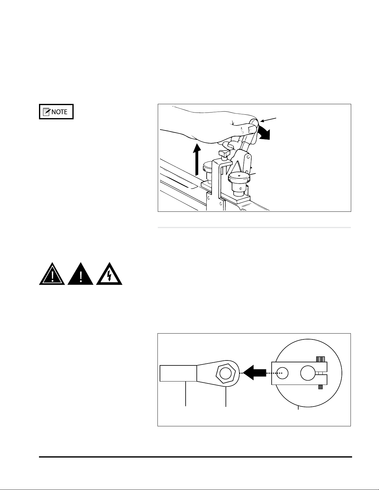
1. Locate the gate adjustment knobs (Figure 2-3) and turn com-
pletely in a clockwise direction to raise hopping rollers.
2. Then, locate the vertical adjustment lever on the hopping roll-
ers assembly and push down all the way. This will raise the
feed rollers to highest vertical position possible, thus making
for maximum clearance.
STEP 3:
Raising Hopping Rollers
If additional control of material is required
during feeding, you may choose to keep the base’s
hopping roller assembly in the down (or normal)
position.
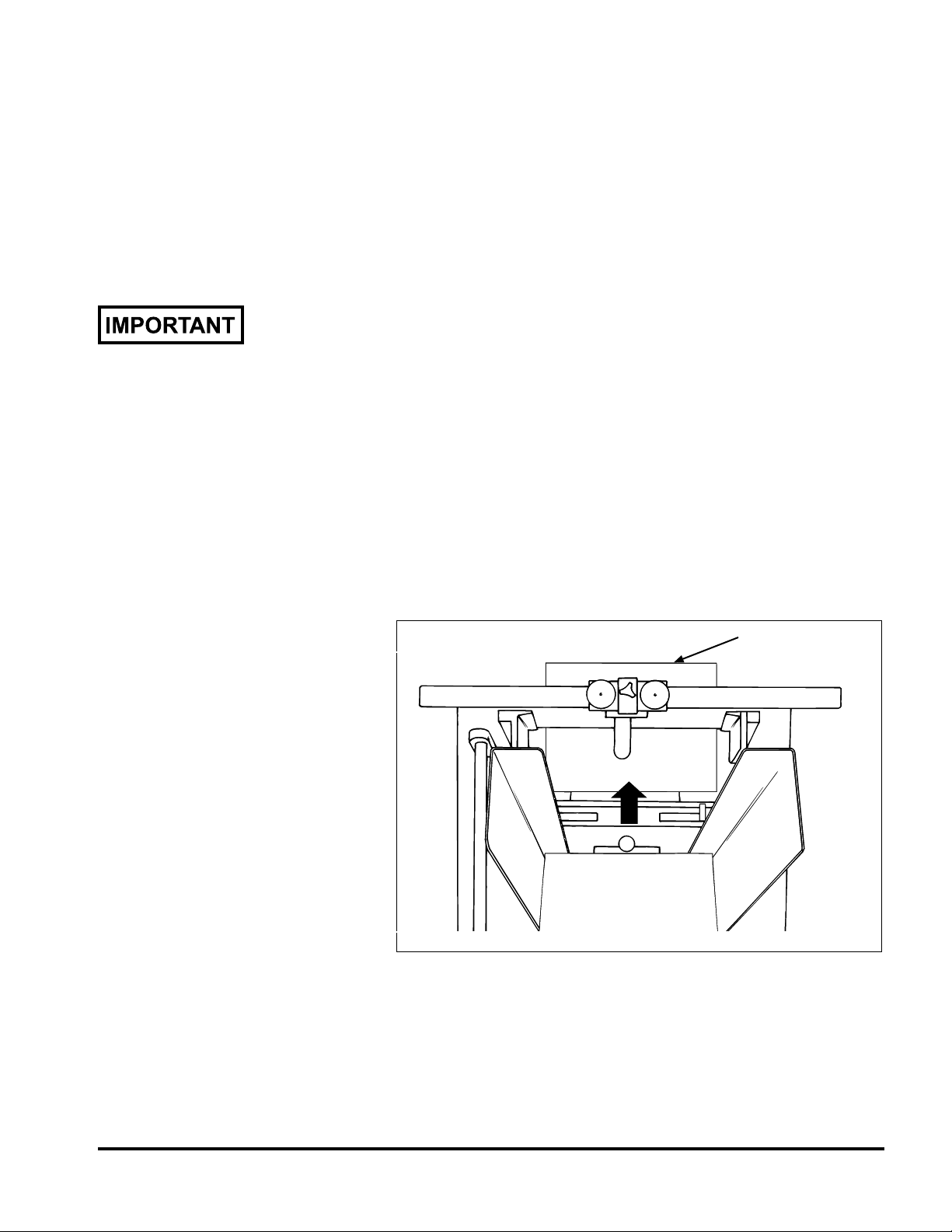
1. Remove side access panel from vacuum base enclosure.
2. Locate the reciprocating arm and reciprocating block directly
beneath the underside of shuttle (Figure 2-4).
3. Using a box wrench, remove the hex-head rod end bearing
bolt holding the reciprocating arm to the reciprocating block.
4. Once the bearing bolt is removed, the reciprocating arm is ef-
fectively disconnected. As the shaft is connected to the shuttle
base plate on the other end, simply allow the shaft to hang
in-position, with no further disassembly.
5. Make sure the base plate of shuttle is all the way forward
(toward the vacuum base gate).
Figure 2-3. Using the Adjustments to Raise Hopping Rollers
STEP 4:
Disabling the Shuttle
To prevent any accidental startup of shuttle
motor and to eliminate the hazard of moving
parts, you can prevent accidental startup by
either disconnecting vacuum base from AC
power at the outlet, or you can remove the
internal AC power fuse (located behind the
access door of the vacuum base).
Figure 2-4. Disabling the Shuttle from Inside the Access
Panel
Vertical adjustment
lever
Gate adjustment
knob
Reciprocating
arm
Hex-head
rod end
bearing bolt
Reciprocating
block

7Value SerieS V-710DM Manual
1. Position photo-eye pointing up and away from feeder and
vacuum base.
2. Lift the feeder onto the top plate of the vacuum base and slide
forward toward the vacuum base gate.
3. Center the feeder between the two side guides as you posi-
tion the feeder fully forward. To verify centering, sight down
the center of the feeder gate, making sure it is in-line with the
vacuum base gate (Figure 2-5).
4. Trap the feeder in-between the vacuum base side guides by
sliding each in toward the side plates of the feeder until they
gently touch. Tighten side guide knobs to secure in position.
1. Connect IEC320 end of power cord to the feeder (at the power
inlet module).
2. Connect three-prong end to nearest AC voltage power source.
STEP 5:
Initial Positioning
of Feeder
Figure 2-5. Positioning the Feeder on the Vacuum Base
STEP 6:
Providing AC Power
to Feeder
Please verify that the voltage shown at the power
inlet module matches the incoming voltage from
the power source.
Center
8
Value SerieS V-710DM Manual
STEP 7:
Checking Material
Discharge from Feeder
Make sure rollers on vacuum base are raised
in the highest vertical position so it does not
interfere with the material.
Figure 2-6. Checking for Proper Material Discharge from
Feeder to Vacuum Base
Leading edge
should be 2/3into
transfer section
As material leaves the feeder gate cylinder, the trailing edge must be
under the hold-down as the leading edge is entering the vacuum base
transfer section. There must be a good transfer of material from the
feeder hold-down to the vacuum base transfer section.
To verify:
1. Slide feeder back far enough to clear the vacuum base side
guides. If necessary, loosen the knobs on both side guides and
pull to the outside slightly to allow movement of the feeder.
2. Insert a piece of material under the hold-down bearings in
such a way that approximately 2/3 of the leading edge is ex-
tending out beyond the feeder (Figure 2-6).
3. Slide feeder back into position, making sure it is again cen-
tered between the side guides. As you do so, make sure the
leading edge of the material moves into the transfer section of
the vacuum base unobstructed.
4. Check to make sure the material is still under the hold-down
bearings and also resting on the vacuum base transfer section.
5. Trap the feeder in-between the side guides until they gently
touch. Tighten side guide knobs.

9Value SerieS V-710DM Manual
STEP 8:
Miscellaneous
Feeder Adjustments
Figure 2-7. Location of Variable Speed Control
Feeder motor stops if turned completely
counterclockwise.
1. Position photo-eye pointing up and away from all objects for
continuous operation.
2. Set the variable speed control (Figure 2-7) to the lowest speed
(counterclockwise). Gradually increase the speed to match the
speed of the vacuum base, thus bringing the gap of the mate-
rial closer together.

10
Value SerieS V-710DM Manual
Installation of the V-710DM Universal Friction Feeder onto the back
deck plate of an inserter is a relatively simple procedure. Several
minor modications to the selected insert station are required prior to
mounting, wiring, and aligning the feeder.
To install the feeder, perform the following steps:
1: Removing rear guide assembly
2: Removing T-plate
3: Repositioning separator foot
4: Removing suction cup and closing off vacuum hose
5: Repositioning insert guide tabs
6: Installing feeder hold-down spring assemblies
7: Aligning feeder with insert station
8: Securing feeder to inserter
9: Installing support pedestal
10: Providing AC power to feeder
11: Initial feeder photo sensor positioning
STEP 1:
Removing Rear
Guide Assembly
At the selected insert station, remove the fasteners that hold the
inserter rear guide assembly to the inserter back deck plate. Lift rear
guide assembly off of back deck plate (Figure 2-8).
Figure 2-8. Removing Guide Assembly Rear from Inserter
Rear guide
assembly
2B:
Inserter Installation

11 Value SerieS V-710DM Manual
STEP 2:
Removing T-Plate
With the rear guide assembly removed, you can now access the in-
serter T-plate. Simply lift off of back deck plate (Figure 2-9).
Figure 2-9. Removing T-Plate from Inserter
T-plate
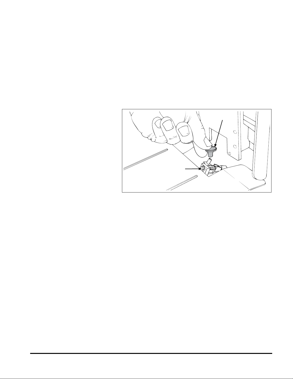
STEP 3:
Repositioning
Separator Foot
1. Locate the separator foot at the front side of the inserter sta-
tion (attached to top rotating shaft).
2. With a screwdriver, loosen the inserter separator foot and tilt
away slightly from insert station assembly (opposite feeder)
so that foot does not interfere with material being fed (Figure
2-10).
3. Retighten to secure.
Figure 2-10. Repositioning Separator Foot at Front of Inserter
Separator foot
12
Value SerieS V-710DM Manual
STEP 4:
Removing Suction Cup
and Closing Off Vacuum
Hose
1. Locate the suction cup and hose from front side of insert sta-
tion.
2. Remove suction cup from vacuum assembly (Figure 2-11).
3. Lower and tilt the adjustable vacuum assembly forward (by
turning the built-in thumbscrew). The vacuum assembly may
be moved down and to one side if it interferes with the mate-
rial being fed.
4. Close off the vacuum hose opening; any convenient plugging
method will do.
Figure 2-11. Removing Suction Cup from Vacuum Assembly
Suction cup
Vacuum assembly
13 Value SerieS V-710DM Manual
STEP 5:
Repositioning
Insert Guide Tabs
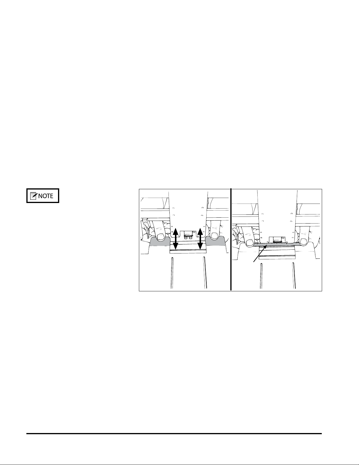
1. Cycle the inserter until the gripper arm jaw is approximately
.5 in. (12.7 mm) from the hopper plate (leading edge of mate-
rial exiting feeder stops here).
2. Locate the two insert guide tabs that protrude from under
the back deck plate. Bend these tabs as required (either up or
down) until their top surface is slightly above the bottom of
the gripper arm jaw (Figure 2-12A). The material to be run
will rest on these tabs. The bottom of the gripper arm jaw
must pass under the material without making contact with it.
3. As it is important that there be adequate clearance between the
guide tabs surface and the gripper jaw, use a at, thin rule (or
gauge) to test for clearance (Figure 2-12B). Ideally, the grip-
per jaw should be fully open when testing.
4. Center the gauge on the guide tabs and slide the gauge back
and forth on the tabs, making sure the gripper jaw does not
touch the bottom of the gauge (Figure 2-12B).
Figure 2-12. Repositioning Guide Tabs and Testing for
Clearance
Mailcrafters' inserters only:
Remove the two insert guide tabs that protrude
from the back deck plate. Make a bend in each
tab approximately 1.375 in. (34.9 mm) from the
tip by placing the tab approximately 1.375 in.
(34.9 mm) into the rear guide assembly. Bend
the tab slightly and repeat same for second tab.
Reinstall insert guide tabs to back deck plate.
Ruler or
gauge
A B
This manual suits for next models
1
Table of contents
Other Thiele Industrial Equipment manuals

Thiele
Thiele TWN 1340/1 User manual

Thiele
Thiele TWN 0796 User manual

Thiele
Thiele TWN 1472 User manual

Thiele
Thiele Streamfeeder Reliant 3700 User manual

Thiele
Thiele Streamfeeder Reliant 3700 User manual

Thiele
Thiele TWN 0812 User manual

Thiele
Thiele TWN 0861 User manual

Thiele
Thiele TWN 0850/1 User manual

Thiele
Thiele TWN 1450 User manual

Thiele
Thiele TWN 0119 User manual


