Thiele Streamfeeder Reliant 3700 User manual

Product Guide
Reliant 3700

Part Number: 00900383
© 2007 Thiele Technologies, Inc. - Streamfeeder. All rights reserved.
No part of this publication may be reproduced, photocopied, stored on
a retrieval system, or transmitted without the express written consent of
Thiele Technologies, Inc. - Streamfeeder.
Thiele Technologies, Inc. - Streamfeeder
103 Osborne Road
Minneapolis, MN 55432-3120 USA
Tel:763.502.0000
Fax:763.502.0100
e-Mail: service@streamfeeder.com
Web: www.streamfeeder.com
Printed in the USA.

Streamfeeder Reliant 3700
Universal Friction Feeder
i
Product Guide
Contents
Before You Begin .........................................................iv
Who Should Read This Manual ............................................................................... iv
How This Manual is Organized ............................................................................... iv
Message Conventions .............................................................................................. vi
Safety...........................................................................vii
Danger .................................................................................................................... vii
Warnings ................................................................................................................. vii
Cautions ................................................................................................................. viii
Labeling ................................................................................................................... ix
Electrical Noise........................................................................................................ ix
Safety Listings and Certifications............................................................................ ix
Specifications ........................................................................................................... x
Section 1: About the Machine........................................................1
Features..................................................................................................................... 1
Main Assemblies .............................................................................................. 1
Control Panel Components ............................................................................... 3
Section 2: Preparing for Operation ...............................................5
Step 1: Gate Assembly Adjustment .......................................................................... 5
Changing from Factory Set High-Tension to Low-Tension ............................. 8
Step 2: Side Guides Setting ...................................................................................... 9
Step 3: Back Wedge Adjustment ............................................................................ 11
Step 4: Top Roller Hold-Down Assembly Setting.................................................. 14
Step 5: Photo Sensor Adjustment ........................................................................... 15
Step 6: Manual Test to Verify ................................................................................. 17
Section 3: How to Operate ...........................................................19
Sequence of Operation............................................................................................ 19
Step 1 — Loading Material in the Hopper ..................................................... 19
Step 2 — Determining Stack Height .............................................................. 20
Step 3 — Powering On Feeder ....................................................................... 20
Step 4 — Setting/Adjusting Speed ................................................................. 21
Step 5 — Running Test Cycles ....................................................................... 21
Step 6 — Final Check..................................................................................... 21
Clearing a Jam ........................................................................................................ 22
Shutdown ................................................................................................................ 22

ii Streamfeeder Reliant 3700
Universal Friction Feeder
Product Guide
Contents
Section 4: Operational Troubleshooting .....................................23
No AC Power to Feeder .......................................................................................... 23
Feeding Doubles ..................................................................................................... 23
Continuous Feeding ................................................................................................ 23
Feed Belts Are Operating, But Material Not Feeding ............................................ 23
Feed Belt(s) Not Tracking on Rollers ..................................................................... 24
Jamming Occurs During Operation ........................................................................ 24
Material Skewing.................................................................................................... 24
Material Too Far from Gripper Jaw (Inserter Applications Only) .......................... 24
Material Too Deep in Gripper Jaw (Inserter Applications Only) ........................... 24
Section 5: Inspection and Care ...................................................25
Visual Inspection .................................................................................................... 25
Checking for Feed and Discharge Belt Wear.................................................. 25
Checking for Timing and Drive Belt Wear ..................................................... 25
Ensuring Proper Feed and Discharge Belt Tracking ...................................... 26
Ensuring Proper Timing and Drive Belt Tracking .......................................... 26
Checking for Gate Assembly Wear................................................................. 27
Advancing O-Ring Gate: Adjusting Worn Rings ........................................... 28
Standard O-Ring Gate: Adjusting Worn Rings ............................................... 28
Replacing Worn Angled Wedge ...................................................................... 28
Preventive Care....................................................................................................... 29
Cleaning Feed and Discharge Belts ................................................................ 29
Cleaning Gate Assembly ................................................................................ 30
Cleaning Photo Sensor ................................................................................... 31
Section 6: Additional Wedges .....................................................33
Load Compensating ................................................................................................ 33
Articulating Roller .................................................................................................. 34
Extended Narrow .................................................................................................... 34
Combination Triangle and Low-Profile .................................................................. 35
Separate Triangle and Low-Profile ......................................................................... 35
Separate Articulating Roller and Low-Profile ........................................................ 36

Streamfeeder Reliant 3700
Universal Friction Feeder
iii
Product Guide
Section 7: Mechanical Components ...........................................37
Low Profile Wedge ................................................................................................. 38
Single S Wedge ....................................................................................................... 40
1 Knob Gate Plate ................................................................................................. 42
Advancing O-Ring Gate with Horizon Adjust and Cover ...................................... 44
Grooved Gum Carriage .......................................................................................... 46
Hold Down ............................................................................................................. 48
Electrical Components ............................................................................................ 50
Base Features 1 ....................................................................................................... 54
Base Features 2 ....................................................................................................... 56
Section 8: Electrical Components ...............................................59
Electrical Wiring Diagram ...................................................................................... 59
Miss Detect Detail .................................................................................................. 60
Double Detect Option Detail .................................................................................. 61
E-Stop Option ......................................................................................................... 62
Power Entry Module............................................................................................... 63
DC Stepping Motor ................................................................................................ 64
Unipolar DC Stepping Motor Drive Board ............................................................ 65
CPU Board Detail ................................................................................................... 66
EPROM Replacement ............................................................................................ 67
Fault Output; How to Configure............................................................................. 68
Optional Burn-Thru Double Detection Calibration Procedure............................... 69

iv Streamfeeder Reliant 3700
Universal Friction Feeder
Product Guide
Section 9: Technical Troubleshooting ........................................71
General Troubleshooting Terms ............................................................................. 71
Gaining Access to the Electronics .......................................................................... 72
Wiring Diagrams .................................................................................................... 72
The Fault Lamp Reset Buttton ............................................................................... 72
Quick-Look Troubleshooting ................................................................................. 73
No Power to Feeder When Power Switch is Turned On .............................. 73
Fuses Blow on Power Up ............................................................................. 73
Decreased Power Experienced After Fuse is Replaced ................................ 74
Decreased Power Experienced After Drive Board is Replaced .................... 74
Motor Does Not Run, is Noisy, Makes a "Growling" Sound or
Runs in Reverse .................................................................................. 74
Drive Board Red LED Illuminated ............................................................... 75
Testing Stepper Motor Drive Board Output Pins ......................................... 75
Fan Does Not Operate/Testing DC Power Supply ....................................... 76
CPU Board "Heartbeat" Pulse Not Present .................................................. 76
On/Off Beeping Sound is Heard................................................................... 77
Steady Beep is Heard.................................................................................... 77
Feeder Will Not Cycle .................................................................................. 79
Testing the Fault Output Connector .............................................................. 80
Testing Motors .............................................................................................. 80
Testing the Transformer ................................................................................ 81
Warranty

Streamfeeder Reliant 3700
Universal Friction Feeder
v
Product Guide
Before You Begin
Who Should
Read This Manual
Welcome to Streamfeeder. This manual was included with your new
Streamfeeder Reliant 3700 Universal Friction Feeder. It provides all
the information you need to efficiently operate and maintain the
product.
This manual is primarily intended for operators who will be using the
Reliant 3700 Universal Friction Feeder in their day-to-day operations.
Please read it thoroughly before you operate the machine.
Qualified technicians should also be familiar with the information in
this manual.
This manual is divided into the following main areas:
•“Safety”: This section is at the front of this manual for good
reason. It covers all safety issues that you should be familiar with
before you go any further with adjustments, power-up, or operation.
• Section 1, “About the Machine”: Introduces you to the feeder. It
provides a complete description of all controls, connectors, and
sensors.
• Section 2, “Preparing for Operation”: Includes all adjustments
you should make before attempting to do a power-up and
successfully run material through the machine.
• Section 3, “How to Operate”: Walks you through the basic steps
needed to run the machine — from power-up to shutdown.
• Section 4, “Operational Troubleshooting”: Gives you the basic
diagnostic information you need to quickly and accurately solve
problems to minimize downtime.
• Section 5, “Inspection and Care”: Covers all the steps you can
take to keep your feeder running properly to minimize downtime
and increase longevity of parts.
• Section 6, “Additional Wedges”: Contains information about the
setup and use of parts which are optional on the Reliant 3700.
• Sections 7 and 8, “Mechanical Components” and "Electrical
Components": These sections contain extensive detailed
information for qualified technicians responsible for servicing and
maintaining the Reliant 3700.
• Section 9, “Technical Troubleshooting”: Gives you the basic
diagnostic information you need to quickly and accurately solve
problems to minimize downtime.
How This Manual
Is Organized
The information in Sections 4 and 9 is designed
to be a quick and easy method for the operator to
minimize downtime. Streamfeeder does not
recommend opening the feeder compartment, or
performing any part replacement based on the
information given in this manual. For more
detailed information, please consult with a
qualified technician.
NOTE

vi Streamfeeder Reliant 3700
Universal Friction Feeder
Product Guide
Before You Begin
Message
Conventions
Here are eight types of messages that appear in this manual which
help emphasize information of particular interest:
DANGER signifies an operator action or specific equipment area that
can result in serious injury or death if proper precautions are not taken.
WARNING signifies an operator action or specific equipment area
that can result in personal injury if proper precautions are not taken.
CAUTION signifies an operator action or specific equipment area that
can result in equipment damage if proper precautions are not taken.
ELECTRICAL DANGER signifies an operator action or specific
equipment area that can result in personal injury or death from an
electrical hazard if proper precautions are not taken.
TIP signifies information that is provided to help the operator mini-
mize problems in the operation of the machine.
NOTE provides useful additional information that the operator should
be aware of to perform a certain task.
CHECK signifies an action that should be reviewed by the operator
before proceeding.
IMPORTANT signifies alerting the operator to actions that can
potentially lead to operational problems or equipment damage if
instructions are not followed properly.
!
!
!
TIP
NOTE
CHECK
IMPORTANT

Streamfeeder Reliant 3700
Universal Friction Feeder
vii
Product Guide
Make sure you thoroughly read this Section until you become familiar
with all the safety issues relating to the safe operation of this machine.
Please read all of the Warnings that follow to avoid possible injury.
Although Streamfeeder has made every effort to incorporate safety
features in the design of this machine, there are residual risks that do
exist that an operator should be aware of to prevent personal injury.
Please read all of the Cautions that follow to prevent damage to the
machine. The Reliant 3700 Universal Friction Feeder is built with the
highest quality materials. However, damage can occur if the machine
is not operated and cared for within design guidelines as
recommended by Streamfeeder.
•Equipment interior contains incoming 120- or 240-VAC
electrical power. Bodily contact with these high voltages can
cause electrocution, which can result in serious injury or death.
•When operating the feeder, always make sure the discharge
safety shield is in the closed position (covering the discharge
belts and rollers). Failure to do so may expose your hands or
fingers to moving parts which can cause serious injury.
•When performing service or maintenance on the feeder, always
lift the discharge safety shield to disengage the safety interlock,
turn Off the main power switch, and disconnect the feeder from
the electrical power source. Failure to do so may expose you to
dangerous high voltage or moving parts which can cause serious
injury.
•When performing initial adjustments prior to operation, always
make sure you lift the discharge safety shield to disengage the
safety interlock, turn Off the main power switch, and
disconnect the feeder from the electrical power source. Failure
to do so may expose you to a potential start-up and moving parts
which can cause serious injury.
•Make sure you always plug the machine into a 3-prong,
properly grounded and fused electrical power source. Never
remove or disable the grounding lug at the outlet. Failure to follow
these warnings may expose you to dangerous high voltage which
can cause serious injury.
Safety
Danger
Warnings
!
!

viii Streamfeeder Reliant 3700
Universal Friction Feeder
Product Guide
•Do not attempt to make any adjustments while the machine is
running. Failure to follow this warning may expose you to moving
parts which can cause serious injury.
•Never attempt to clear a jam from the machine until you turn
Off the main power switch and disconnect the machine from
the electrical power source. Failure to do so may expose you to a
potential start-up and moving parts which can cause serious injury.
•Do not attempt to gain access to the inside of the feeder. Refer
all questions or problems to a qualified technician.
•When the machine is not in use, avoid stacking or storing
materials on the carriage assembly to prevent damage to the
belts.
•When replacing fuses, always use the exact type supplied with
the machine as shipped from the factory. IMPORTANT: Always
make sure power module is replaced exactly as removed.
Failure to follow this caution can result in damaged electrical
parts.
•When performing routine cleaning of parts, only use those
methods and cleaning solvents (isopropyl alcohol) which are
specified by Streamfeeder. Failure to do so may cause
unpredictable results and can cause damage to machine parts. See
Section 5, Inspection and Care, for recommendations.
•Do not attempt to use the machine for any other purpose other
than what was recommended by Streamfeeder. Failure to follow
this caution may cause unpredictable performance, and/or can cause
damage to machine parts.
•Avoid leaving any loose cabling near any moving parts. Failure
to follow this caution may result in damage to machine parts.
•Avoid any type of direct impact to the sensor and extension
assembly. Failure to follow this caution will cause damage to the
photo sensor or extension.
•Do not apply lubricants to any part of the machine.
• Do not attempt to gain access to the inside of the feeder. Do not
attempt to remove and replace parts. Refer all questions or
problems to a qualified technician.
Warnings
(cont.)
!
Cautions
!

Streamfeeder Reliant 3700
Universal Friction Feeder
ix
Product Guide
Electrical Noise
Labeling
The air contains electromagnetic interference (EMI) fields and radio
frequency interference (RFI), also known as “electrical noise.”
Usually this noise is small enough in size (amplitude) to not be a
problem. If intense enough, however, it can cause problems for other
electrical equipment.
Streamfeeder has designed the feeder with noise immunity in mind.
Even the sensors provided with the machine have a certain amount of
noise immunity built-in. However, in extremely noisy environments,
these design considerations are not necessarily immune to electrical
noise and therefore, operational problems can occur. If you suspect
any such electrical noise problems, please report it to a qualified
technician.
Streamfeeder has affixed safety labels to those areas of the Reliant
3700 Universal Friction Feeder where potential operator hazards do
exist (such as moving belts or rollers). Shown below are label
examples, along with their respective locations.
Safety Listings and
Certifications
This symbol on the back panel means the product is in
compliance with the following standards under the
provisions of the Machinery Directive 89/392/EEC
and the amendments 91/368/EEC, 93/44/EEC and
93/68/EEC, and the EMC Directive 89/336/EEC.
Discharge
Safety Shield
Feed Belt
Guards

xStreamfeeder Reliant 3700 Universal Friction Feeder
Product Guide
Maximum Product Size: 11.75 in. W x 14 in. L(298.5 cm x 355.6 mm)
Minimum Product Size: 3.75 in. W x 3.75 in. L(95.3 cm x 95.3 mm)
Optional: 2 in. W x 2.5 in. L(50.8 cm x 63.5 mm)
Min/Max Product Thickness: .003 in. to 1 in. (.076 mm to 25.4 mm)
Speed: 5700 in/min (144,780 mm/min)
Batch Size: 1 to 99 pieces
Modes: One shot or batch count
Electrical Requirements: 115/230vac, 50/60 Hz, 3A
Weight: 75 lb. (34 kg)
Warranty: One-year limited
6SHFL¿FDWLRQV

Streamfeeder Reliant 3700
Universal Friction Feeder
1
Product Guide
1About Your Machine
The Reliant 3700 Universal Friction Feeder is designed for reliability,
flexibility, and ease of use with a variety of host systems. Included are
such applications as gripper arm envelope inserters and infeed
conveyors for various wrapping machines.
All parts required for setup, loading, feeding, sensing and easy
operator control are combined into one compact unit.
Review the main assemblies in Figure 1-1 to become familiar with
names and locations of feeder parts and adjustments. This will help to
prepare you for initial setup. Descriptions are found in Table 1-1.
Review the control panel components in Figure 1-2 to become
familiar with names and locations of specific connectors, switches,
and controls. This will help to prepare you for installation and
operation. Descriptions are found in Table 1-2.
AC Power
Cord
Figure 1-1. Main Assemblies of the Reliant 3700 Universal Friction Feeder
• Feeders can be configured two ways: one-shot
mode or batch count mode.
•One-shot mode feeders are capable of feeding
one piece of material when a flight signal is
received.
•Batch count mode feeders are capable of
feeding 1-99 pieces of material when a flight
signal is received.
• For purposes of illustration, a batch count
feeder is shown in all drawings of this manual.
NOTE
Features
Main Assemblies
Not Shown:
• Side Guides (2)
• Fault Output I/O Cable
• Low Profile Wedge
Flight-Detect
Sensor
Loose Parts Supplied When Shipped
Side Guides
(adjustable)
Control Panel
(this side)
Table Top
Photo Sensor and Flexible Extension
Discharge Belts
Discharge Safety
Shield
Top Roller
Hold-Down Assembly
(adjustable)
Gate Assembly
and Adjustment
Single S Wedge
and Adjustments
Feed Belts

2Streamfeeder Reliant 3700
Universal Friction Feeder
Product Guide
Gate assembly and adjustment Mounted on a gate bracket assembly above the feed belts, this device
provides a curvature to help preshingle stacked material. When properly
adjusted, a clearance is created to help singulate and feed material.
(Note:
For multiple page material, a 1 to 1.5 maximum thickness is typical.)
Table top Used to support the back wedge.
Side guides (adjustable) Holds a stack of material to be fed and helps keep it straight for proper
entry through the gate assembly area. Single adjustment knob allows you
to move side guides together or apart for different size material. Can be
positioned equally or offset.
(Note: Dual-knob design also available.)
Back wedge and adjustment Lifts the material to keep it off the table top, reduces excessive contact
with the feed belts, and helps push the material against the curvature of
the gate assembly. To achieve proper lift, adjustment wing-nuts and
locking levers allow you to slide the wedge to various positions and
angles.
Photo sensor and flexible extension Also called a
sheet-detect
photo sensor, it “looks” for the leading edge of
the material to stop the feeder. For optimum setting, a flexible extension
allows you to adjust for distance and perpendicular angle to material.
Feed belts and discharge belts
Feed belts:
Provides the friction and motion necessary to pull individual
material from the bottom of the stack and through the gate assembly area.
Discharge belts:
Combined with the top roller hold-down assembly,
provides the friction and motion necessary to pull material away from the
gate assembly area.
Top roller hold-down assy (adjustable) A block of small rollers mounted on a movable shaft. Used to gently force
the material down on the discharge belts so that it can be controlled after it
exits the gate assembly area. To achieve proper downward pressure,
T-nuts allow you to loosen the shaft to adjust block up or down.
Control panel All connectors and switches for sensor, interface, and AC power are
located here. For descriptions, see Figure 1-2 and Table 1-2.
Discharge safety shield Provides residual risk protection to operator when feeder is running.
Built-in interlock switch stops the feeder when opened.
LOOSE PARTS
AC power cord, 8 ft. (2.44 m) IEC320 removal three-prong. Shipped loose.
Flight-detect sensor Mounted at a remote location. It "looks" for a target on-line (such as a
hold-down ski or conveyor lug) to start the feeder.
Fault output I/O cable Provides the interface for host system integration.
Product Description Section 1
Table 1-1. Main Assemblies Feature Descriptions
Feature Description

Streamfeeder Reliant 3700
Universal Friction Feeder
3
Product Guide
Figure 1-2. Control Panel Components
Control Panel Components
AC Power
Cordset
Connector
Power On/Off
Fuse Holder
Batch Count
Thumbwheels
(Optional)
Cycle
Button
Variable
Speed
Control
Feed/Flight
Trigger
Connector
Reset Button/
Fault Indicator
03
CYCLE
-+
SPEED

4Streamfeeder Reliant 3700
Universal Friction Feeder
Product Guide
Feature Description
AC power cordset connector Cordset plugs into this IEC320 connector to provide feeder with power
from a grounded/fused outlet. Switchable for either 115- or 230-VAC.
Feed/flight trigger connector The remote flight-detect sensor plugs into this 4-pin connector to provide
the “start” signal to begin a feed cycle.
Power On/Off Toggles AC power On or Off.
Fuse holder Contains two replaceable GMD3, 3-Amp, 5-mm fuses.
IMPORTANT:
Always make sure power module is replaced exactly as removed. Failure
to follow this caution can result in damaged electrical parts.
Reset button/fault indicator Labeled Reset, the primary purpose of this pushbutton switch/indicator is
to reset the feeder after: 1) a “time-out” occurs or, 2) the discharge safety
shield is opened or, 3) "miss-feed" occurs. Time-outs occur: 1) during a
misfeed or, 2) when the hopper runs out of material; or 3)
flashing
during
"miss" condition. Built-in indicator illuminates: 1)
steady
during a time-out
condition; 2)
flashing
during an “open” discharge safety shield.
Variable speed control This dial switch (labeled Speed) allows the feeder speed to be
synchronized with an inserter, or infeed conveyor. Turning counter-
clockwise decreases speed; clockwise increases speed.
Cycle button This pushbutton switch (labeled Cycle) is primarily used during
preparation and test, this is used to manually start (or run) a feeder cycle.
To “start” a cycle, push Cycle completely in and then release.
Batch count thumbwheels (optional)
Note: Batch count feeders only.
These two wheels allow you to select a
number from 1 to 99 to which the feeder will always count and then stop.
Fault ouput connector (not shown) The fault output I/O cable plugs into this connector to provide the host
system interface.
Fault configuration selector switch This switch allows the operator to select between stopping the feeder
(not shown) or sounding an alarm only when a fault is detected.
Table 1-2. Control Panel Feature Descriptions

Streamfeeder Reliant 3700
Universal Friction Feeder
5
Product Guide
2Preparing for Operation
!
!
!
When performing initial feeder adjustments
prior to operation, always make sure you turn
Off the main power switch and disconnect all
equipment from the electrical power source.
Failure to do so can expose you to a potential
startup and moving parts which can cause
serious injury.
Do not attempt to make any adjustments while
the feeder and machine of application are
running. Failure to do so can expose you to
moving parts which can cause serious injury.
Do not wear loose clothing when operating the
feeder.
Avoid making adjustments with loose or
unsecured parts. This can potentially damage
parts.
STEP 1:
Gate Assembly
Adjustment
Review
The gate assembly provides the curvature to help preshingle material
and the proper gap to help the feed belts pull material through the gate
assembly area — one at a time. The downward pressure (or weight) of
the stack in the hopper will provide the force to help push the material
against the curvature of the gate assembly, and help it contact the feed
belts. This preshingling will allow the gate assembly to efficiently
separate (and singulate) material.
To achieve the optimum separation, you have to use the adjustment
knob to either increase (clockwise) or decrease (counterclockwise) the
gap between gate assembly and the feed belts. Depending on the
characteristics of the material you are using, you may have to change
the gate assembly from the factory-set high spring tension to a low
spring tension. See “Changing from Factory Set High-Tension to
Low-Tension” to follow (page 7).
Objective
Adjust the gate assembly for minimum gap, with minimum pressure
on the material. Your objective is to adjust the clearance so that a
single piece of material passes without resistance. The optimum
setting should be a gap adjustment of 1.5 thickness of material.
NOTE
NOTE
Keep in mind the gate assembly works with the
wedge to provide the proper lift, curvature of the
material, and proper belt/material contact to
separate and feed one piece at a time.
Hopper refers to the space where the material is
stacked (made up of the side guides).
IMPORTANT
Feeding problems will occur with either too much
material in the hopper, or too large a gap
between the gate assembly and the material.
Once the Streamfeeder Reliant 3700 Universal Friction Feeder is
installed on your host system, you are ready to prepare the machine
for operation. To do so, you must perform several adjustments with
the material you are going to be feeding. And, you must do a test run
with this material to verify it is set correctly before you begin cycling
the feeder with your particular application. You will have to perform
this procedure for material you plan to feed.
The adjustments you must make (in order) are as follows:
1: Gate assembly adjustment
2: Side guides setting
3: Back wedge adjustment
4: Top roller hold-down assembly setting
5: Photo sensor adjustment
6: Manual test to verify

6Streamfeeder Reliant 3700
Universal Friction Feeder
Product Guide
Preparation and Adjustments Section 2
Procedure
To adjust the gate assembly for proper gap, follow these steps:
1. Slide two pieces of sample material under the gate assembly.
You may have to pull up on the adjustment knob to allow the
material to be inserted (Figure 2-1).
2. Test the top piece for clearance. Grasp with two hands and
slide it front-to-back under the gate assembly (Figure 2-2). A
proper adjustment allows a “slight” amount of drag on the top
piece of material.
3. With the top piece removed, test the bottom piece of material
for clearance. It should move freely, without any resistance.
4. Adjust the knob on the gate assembly until the material has
the desired drag: clockwise to increase clearance,
counterclockwise to decrease clearance (Figure 2-3).
5. Remove the top piece and turn the adjustment knob
counterclockwise 1/4 turn to lower the gate assembly. This
should set the gap for the optimum 1.5 thickness of material.
6. Repeat drag tests and adjust as needed until the desired
clearance is achieved.
STEP 1:
Gate Assembly
Adjustment
(continued)
!
Excessive lowering of the gate assembly can
damage material or lead to premature wear of the
O-rings or feed belts.
Figure 2-1. Lifting Gate Assembly Upward to Insert Material
Figure 2-2. Using Two Pieces of Material to
Set Gap
Figure 2-3. Adjusting Gate Assembly for Correct
Gap
TIP
A wider gap between material and belt provides
the highest tolerance for curled and bent edges.
L
O
W
E
R
If bottom piece of material does not move freely,
then the gate assembly is too tight. This can lead
to premature wear of the O-rings or feed belts.
Pull knob up
Slip sheet of
product under
gate assembly
Move
product
front to back
test for
slight drag
Turn knob
counter-
clockwise to
lower (or
decrease
gap)

Streamfeeder Reliant 3700
Universal Friction Feeder
7
Product Guide
STEP 1:
Gate Assembly
Adjustment
(continued)
NOTE
When feeding product with varying thickness
throughout, it may be necessary to turn both
adjustment rollers 1-2 full turns
counterclockwise to compensate for the
differential thickness. This procedure allows the
gate horizon to “float.”
IMPORTANT
The adjustment knob set screws are pre-set at the
factory to lock the knob to the threaded rod. DO
NOT OVER-TIGHTEN! Over-tightening the set
screws may damage the components.
To adjust the gate for effective material skew control, follow these
steps:
1. Repeat drag test.
2. Test the piece for uneven side-to-side drag. Grasp with two
hands and slide it front-to-back under the gate assembly. A
proper adjustment allows for equal drag on the left and right
sides of the piece of material.
3. To compensate for greater drag on one side of the material,
turn the opposite adjustment roller counterclockwise 1/8 turn.
Next, turn the other adjustment roller clockwise 1/8 turn.
4. Repeat drag tests and adjust as needed until equal drag is
achieved. You may need to repeat this procedure after
observing the feeder cycling (refer to Section 3, How to
Operate).
Figure 2-4. Horizon Adjustment (shown on Advancing O-Ring
Gate)

8Streamfeeder Reliant 3700
Universal Friction Feeder
Product Guide
Review
The Reliant 3700 is shipped to you with a high-tension spring in the
gate assembly. This works well for most materials, allows for tall
stack height, and helps provide the best performance in preventing
doubles. However, certain types of material may demand that you
change the gate assembly from a high-tension setting to a low-
tension setting (for example, irregular shaped material).
If you are feeding a material of irregular thickness, you should
change to low-tension. This provides the following benefits:
1) allows the gate assembly to adjust to the irregular thicknesses.
2) prevents marking on the material by the gate assembly.
3) prevents peeling back the top sheet of a multi-page item.
Procedure
To change the spring from a high to a low tension, follow these
steps:
1. Remove the gate assembly from gate bracket assembly. To
do so, pull cylinder down with one hand, lift up on knob
with other, and tip at slight angle to remove.
2. Remove the adjustment knob by turning counterclockwise
(Figure 2-5A). Then lift the cylinder off of top of spring
(Figure 2-5B).
3. Turn the cylinder around so the cylinder collar faces up
(Figure 2-5C). Then place the cylinder on top of the spring.
4. Replace the adjustment knob (make about 8 revolutions of
the knob before reinstalling gate assembly on gate plate).
Changing From
Factory Set
High-Tension to
Low-Tension
IMPORTANT
When changing from a low-tension to high-
tension setting, you may have to adjust the
stack height downward to prevent feeding
problems.
!
Excessive lowering of the gate assembly can
damage material and/or lead to premature
wear of the O-rings or feed belts.
NOTE
Certain types of single-sheet material may
require even more tension than the high-
tension setting can provide. To increase
tension even further, place a washer between
the cylinder and spring.
Washer
C
AB
Figure 2-5. Adjusting Gate Assembly for Low-Tension
Other manuals for Streamfeeder Reliant 3700
1
Table of contents
Other Thiele Industrial Equipment manuals

Thiele
Thiele TWN 0835/1 User manual

Thiele
Thiele TWN 0812 User manual
Thiele
Thiele TWN 0119 User manual
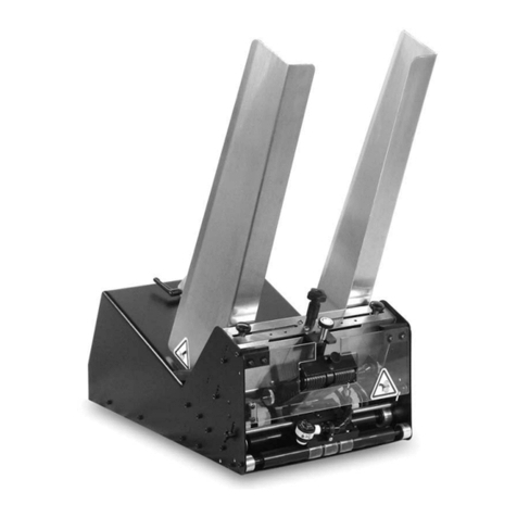
Thiele
Thiele Streamfeeder Reliant 3700 User manual
Thiele
Thiele Streamfeeder Value Series User manual
Thiele
Thiele TWN 1450 User manual

Thiele
Thiele TWN 1472 User manual
Thiele
Thiele TWN 0861 User manual
Thiele
Thiele TWN 0850/1 User manual

Thiele
Thiele TWN 0796 User manual
