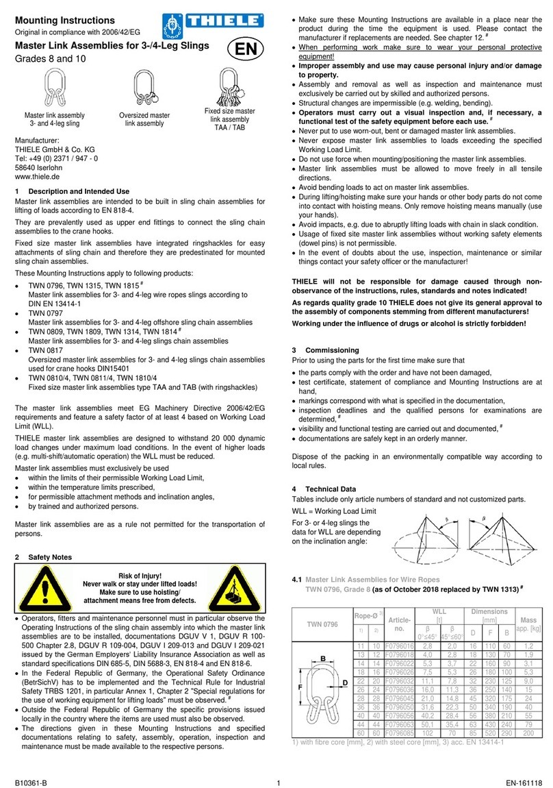
MOUNTING INSTRUCTIONS
LASHING POINTS TWN 1472, TWN 1473
THIELE GmbH & Co. KG # identifies revisions
www.thiele.de | info@thiele.de B09059-C replacement for B09059-B
© All rights reserved EN 08.2021 2 | 4
5WELDING INSTRUCTIONS
5.1 General #
Material of the weld-onsupport: S355NL or S355J2
Material of the weld-onjoint: C22, S235, S355 or similar
The following general welding instructions must be observed:
•EN ISO 2560 Welding consumables –Covered electrodes for manual arc
welding of non-alloy and fine grain steel
•EN ISO 14341 Welding consumables –Wire electrodes and weld
deposits for gas shield metal arc welding of non-alloy
and fine grain steel
•ISO 3834-2 Quality requirements for fusion welding of metallic
materials
•EN 1011-1, 2 Welding –recommendations for welding of metallic
materials
•EN ISO 9606-1 Qualification testing of welders –fusion welding
•DVS 0702-1 / 0711 Factsheet - Requirements for operation and personnel
•SEW 088 Weldable unalloyed and low-alloyed steels –
Recommendations for processing#
Welding is only permitted by trained and authorised personnel in accordance
with the qualification according to EN ISO 9606-1.#
The positions of the welds are marked red in the sketch:
Take care to intermit the weld seam in the
center on the outside to enable water to
flow out.
Welding on the movable ring is not allowed!
5.2 Preparations
Make sure the welding surfaces are grinded down, flat, dry, free of impurity,
flawless and weldable (material see ISO/TR 15608 table 1, group 1).
Make sure the mounting place is able to absorb the maximum specified lashing
capacity multiplied with a safety factor of 1,25 without safety reducing
deformation.
5.3 Requirements
The mounting location for each lashing point has to ensure that
•no areas of danger are created (crushing point, shearing point),
•transportation is not restrained by overhang,
•used lashing means (e.g. hooks) are freely movable and will not be bended,
•lashing accessories will not be bypassed,
•incorrect use is avoided,
•lashing points cannot be damaged,
•they can be reached easily and without obstruction for attaching and detaching
the lashing means. #
Observe the welding instructions listed.
The lashing points must be inspected by an expert after welding and before first
use. This inspection must be documented.#
5.4 Welding dimensions
Sketch:
5.5 Welding sequence
1. Check the suitability of the attachment location especially concerning to
stability, weldability and a safety use.
2. Position the lashing point and mark the position of the first weld-on
support.
3. Fix the first support and make the root run.
4. Clean the root run and make the final runs.
5. Position the ring with one end into the first support and then the second
support atop the free end of the ring. Consider and check dimension E.
Fix the second support by tack-welding.
6. Check dimension E and check the ring can move to 180 °.
Readjust the second support if necessary.
7. Weld the second support as the first one.
8. Check a smooth movement of the ring at last.
Do it analogously the same way for an assembly of single rings within a steel
construction.
5.6 Miscellaneous
1. Minimum notched-bar impact strength values of ISO-V specimens KV=27J at
-40 °C (e.g. S355J4G3 or S355NL, EN10025)
2. When selecting material grades other than those listed above please contact
the base material and filler metal manufacturers for information.
3. The responsible welding supervisor on site must make sure the welding
current is correctly adjusted to suit the given welding position.#
4. Check the welds for cracks, inclusions and blowholes.
5. A procedure check is recommended to confirm the selected settings.#


