Thiele TWN 1340/1 User manual

MOUNTING INSTRUCTIONS
HOOKS GRADES 80 AND 100
THIELE GmbH & Co. KG # change indicator
www.thiele.de
| info@thiele.de B11090-C replaces B11090-B
All rights reserved. US 02.2022 1 | 7
Sling
h
ooks
with clevis
TWN 1340/1
TWN 1840/1
Sling
h
ooks
with eye
TWN 0855/1
TWN 0858/1
TWN 1841/1
Foundry
hooks
TWN 0859
TWN 085
TWN 185
Swivel
hooks
TWN 0854
TWN 0887
Lifting
h
ook
for engines
TWN 0889
The following mounting instructions must always be
followed to avoid the risk of personal injury or property
damage.
Do not use a hook before reading these mounting
instructions.
1. ABOUT THIS INSTRUCTION
These mounting instructions describes in particular how sling
hooks according to TWN 1340/1, TWN 1840/1, TWN 0855/1,
TWN 0858/1, TWN1841/1, TWN 0859, TWN 0856, TWN 1856,
TWN 0854, TWN 0887, TWN 0889 (TWN = THIELE Works
Standard) are to be safely used for lifting purposes.
The instruction applies analogously to components of identical
design.
To comply with these instructions is essential to help avoid
hazards and increases the reliability and service life of the hooks.
DANGER! Indicates a hazardous
situation which, if not avoided, will
result in death or serious injury.
WARNING! Indicates a hazardous
situation which, if not avoided, could
result in death or serious injury.
CAUTION! Indicates a hazardous
situation which, if not avoided, could
result in minor or moderate injury.
NOTICE! Is used to address practices
not related to physical injury.
Safety Instructions signs indicate
specific safety-related instructions or
procedures.
Chains and accessories marked with the American nominal size
7/32” already corresponded to European nominal size mm.
In order to achieve a better match, the previous nominal size
7/32" is now converted to the new nominal size 1/4”.
The working load limits have now also been adjusted.
DEFINITIONS
Clevis
A U-shaped fitting with pin.
Working load limit (WLL)
The maximum load which a hook is designed to support without
shock-loading.
Read ASME B30.10 „Hooks“.
2. BASIC SAFETY REQUIREMENTS
To prevent the risk of injury never walk or stay under lifted
loads!
The working load limit must not be exceeded!
Hooks as well as lifting and attachment means to be used
must be free from defects!
Working under the influence of drugs, medications
impairing the sense and/or alcohol is strictly forbidden!
•Operators, fitters and maintenance personnel must in
particular observe the mounting and operating instructions
of the chain slings into which the hooks are to be installed as
well as standards ASTM A 906/A 906 M (Standard
Specification for Grade 80 and Grade 100 Alloy Steel Chain
Slings for Overhead Lifting), ASTM A 952/A 952 M (Standard
Specification for Forged Grade 80 and Grade 100 Steel Lifting
Components and Welded Attachment Links), ISO 3056 (Non-
calibrated round steel link lifting chain and chain slings; Use
and maintenance), ISO 7593 (Chain slings assembled by
methods other than welding; Grade T(8)) and ISO 4778
(Round steel short link chains for lifting purposes – Chains
slings of welded construction – Grade 8), ISO 1837 Lifting
hooks - Nomenclature.
#
•The specific safety and operating regulations and standards
issued locally in the country where the items are used must
be observed.
•During operation work, wear your personal protective
equipment!
MOUNTING INSTRUCTIONS
HOOKS GRADES 80 AND 100
THIELE GmbH & Co. KG # change indicator
www.thiele.de
| info@thiele.de B11090-C replaces B11090-B
All rights reserved. US 02.2022 2 | 7
•The directions given in these mounting instructions and
specified documentations relating to safety, assembly,
operation, inspection, and maintenance must be made
available to persons operating and using the hooks.
•These mounting instructions must be available in a place
near the product during the time the equipment is used.
Please contact the manufacturer if replacements are
needed. Also see chapter 11.
•Improper assembly and use may cause personal injury
and/or damage to property.
•Assembly and removal as well as inspection and
maintenance must exclusively be carried out by skilled,
qualified, trained and authorized persons only.
•Structural changes are impermissible (e.g. welding, bending).
•Operators must carry out a visual inspection and, if
necessary, a functional test of the safety equipment before
each use.
•Never use worn-out, bent or damaged hooks.
•Only lift loads that do not exceed the working load limit of
the corresponding chain sling.
•Never expose hooks to loads exceeding the specified
working load limit.
•Do not use force when mounting/positioning the hooks.
•No one including you (operator) must be in the way of the
moving load (hazard area).
•Do not tip-load a hook.
•Hooks shall have well-functioning safety latches.
•Avoid bending loads to act on chain links and hooks.
•Avoid sharp edges. Use edge protectors or reduce the WLL
by 20 %.
#
•Only lift loads that are freely movable and not attached or
fastened.
•Always monitor a suspended load.
•During lifting your hands or other body parts must not come
into contact with lifting means. Only remove lifting means
manually (use your hands).
•Avoid shock loads, e.g. due to abruptly lifting loads with
chain in slack condition.
#
•Usage without working safety elements (cotter pins, dowel
pins) is not permissible.
•Make sure the load can take the forces to be applied without
suffering deformation.
•Hooks must be allowed to move freely in all tensile
directions.
•Put the load only down in flat places/sites where it can be
safely deposited.
•Avoid hooks to get caught under the load.
#
•In the event of doubts or concerns about the proper and safe
use, inspection, maintenance or similar things contact your
safety officer or the manufacturer.
THIELE is not responsible for damage caused by non-
observance of the instructions, rules, standards and notes
indicated!
As regards grade 100, THIELE does not give its approval to the
assembly of components sourced from different
manufacturers!
As a rule, hooks and chain slings are not permitted for the
transportation of persons.
3. DESCRIPTION AND INTENDED USE
THIELE hooks are exclusively intended as end fittings for the
usage in chain slings according to ASTM A 906/A 906M.
The connection to the sling chain is made directly by the clevis
or indirectly by using connecting links which are assembled to
the eye.
Hooks with eye can also be used within welded chain slings.
Hooks must exclusively be used
•within the limits of their permissible working load limits,
•for permissible attachment methods and sling angles,
•within the temperature limits prescribed,
•by trained and authorized persons.
Failure to do so may cause serious injury or property damage.
THIELE hooks meet EC Machinery Directive 2006/42/EC
requirements and feature a safety factor of at least 4 based on
the working load limit.
THIELE hooks are designed to withstand 20 000 dynamic load
changes under maximum load conditions. In the event of higher
loads (e.g. multi-shift/automatic operation) the working load
limit must be reduced.
They are marked with the corresponding chain size, grade,
manufacturer’s symbol and traceability code.
Hooks with safety device can also be used within lashing chains.
When used within a lashing system the maximum lashing
capacity is obtained by doubling the working load limit.
Any alternating use for lifting and lashing purposes is
impermissible!
MOUNTING INSTRUCTIONS
HOOKS GRADES 80 AND 100
THIELE GmbH & Co. KG # change indicator
www.thiele.de
| info@thiele.de B11090-C replaces B11090-B
All rights reserved. US 02.2022 3 | 7
4. COMMISSIONING
Prior to using the components for the first time assure that
•the hooks comply with the order and have not been
damaged,
•test certificates and mounting instructions are at hand,
•markings correspond with what is specified in the
documentation,
•inspection deadlines and the qualified persons for
examinations are determined,
•visibility and functional testings are carried out and
documented,
•documentation is safely kept in an orderly manner.
Dispose of the packing in an environmentally compatible way
according to local rule.
5. TECHNICAL DATA
Tables include only article numbers of standard and not
customized parts.
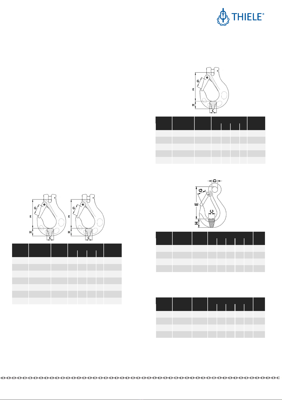
5.1 Sling hooks ith clevis,
TWN 1340/1, grade 80
Executions according to TWN 1340 without safety latch.
Nominal
size
Article
no.
WLL
[lbs]
Dimensions [mm] Mass
[lbs]
E G H C
1/4 F336010 2 500 75 24 20 17
0.79
5/1 F336110 4 500 92 30 25 22
1.65
3/8 F336210 7 100 113 37 32 28
3.09
1/2 F336310 12 000 133 42 41 35
5.51
5/8 F336410 18 100 162 51 50 41
9.70
3/4 F33656
1)
28 300 220 65 58 55
21,3
7/8 F33661
1)
34 200 244 75 64 61
23,4
1) TWN 0835/1
5.2 Sling hooks ith clevis,
TWN 1840/1, grade 100
Executions according to TWN 1840 without safety latch.
Nominal
size
Article
no.
WLL
[lbs]
Dimensions [mm] Mass
[lbs]
E G H C
1/4 F336050 3 100 75 24 20 17
0.79
5/1 F336150 5 700 92 30 25 22
1.65
3/8 F336250 8 800 113
37 32 28
3.09
1/2 F336350 15 000 133
42 41 35
5.51
5/8 F336450 22 600 162
51 50 41
9.70
5.3 Sling hooks ith eye, TWN 0855/1, grade 80
Nominal
size Article no.
WLL
[lbs]
Dimensions [mm] Mass
[lbs]
E D G H C
3 -8 Z06159 88 200 388
72 109
103
78 71.21
40-8 Z06160 110 200
442
84 124
116
89 103.6
45-8 Z06161 138 900
494
90 138
130
99 142.0
50-8 Z06162 176 400
610
102
155
145
110
180.6
5.4 Sling hooks ith eye, TWN 0855, grade 80
Without safety latch.
Nominal
size Article no.
WLL
[lbs]
Dimensions [mm] Mass
[lbs]
E D G H C
3 -8 Z04079 88 200 388
72 109
103
78 69.45
40-8 Z04083 110 200
442
84 124
116
89 101.4
45-8 Z04080 138 900
494
90 138
130
99 138.9
50-8 Z04081 176 400
610
102
155
145
110
176.4
MOUNTING INSTRUCTIONS
HOOKS GRADES 80 AND 100
THIELE GmbH & Co. KG # change indicator
www.thiele.de
| info@thiele.de B11090-C replaces B11090-B
All rights reserved. US 02.2022 4 | 7
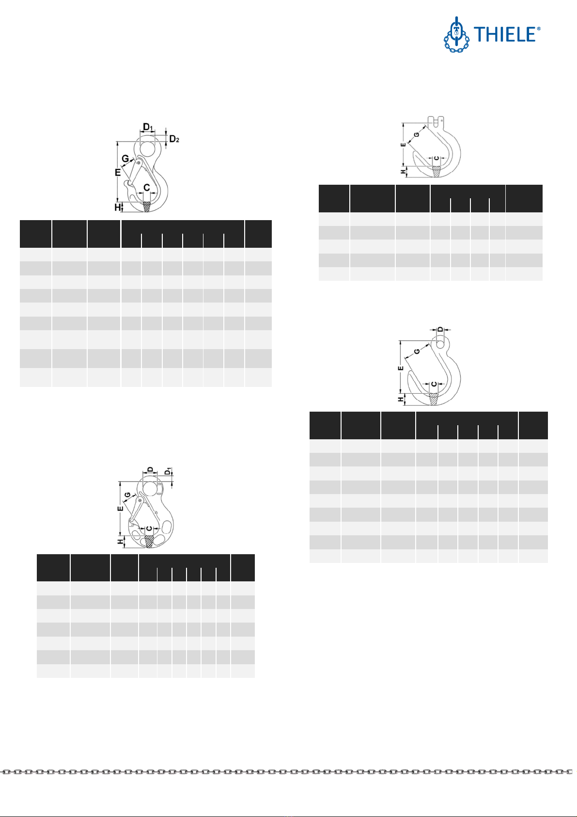
5.5 Sling hooks ith eye, TWN 0858/1, grade 80
Executions according to TWN 0858 without safety latch.
Nom.
size
Article
no.
WLL
[lbs]
Dimensions [mm] Mass
[lbs]
E D D
1
G H C
1/4 F32901 2 500 91 21 11 23 17 16 0.66
5/1 F32911 4 500 120 28 14 30 24 22 1.76
3/8 F32921 7 100 152 36 18 38 29 28 3.75
½ F32931 12 000 180 42 21 42 41 36 5.51
5/8 F32941 18 100 221 54 27 52 45 43 11.24
¾ F32951 28 300 270 62 30 65 58 55 19.1
7/8
F329710
1)
34 200 271 65 30 70 62 54 21.4
1
F32981
0
1)
47 700 302 70 33 75 71 59 30.9
1-¼
F329910
1)
72 300 352 80 38 90 86 67 55.1
1) New design similar to TWN 1340/1
5.6 Sling hooks ith eye,
TWN 1841/1, grade 100
Executions according to TWN 1841/1 without safety latch.
Nominal
size Article no.
WLL
[lbs]
Dimensions [mm] Mass
[lbs]
E D D
1
G H C
1/4 F32905 3 100 91 21
11
24
20
17
0.75
5/1 F32915 5 700 118
28
14
30
25
22
1.75
3/8 F32925 8 800 145
36
18
37
32
28
3.25
1/2 F32935 15 000
168
42
21
42
41
35
5.63
5/8 F32945 22 600
210
54
25
51
50
41
10.25
7/8 F32975 42 700
271
65
30
70
62
54
21.55
1 F32985 59 700
302
70
33
75
71
59
31.30
5.7 Foundry hooks ith clevis,
TWN 0859, grade 80
Nom.
size
Article
no.
WLL
[lbs]
Dimensions [mm] Mass
[lbs]
E G H C
5/1 F33310 4 500 110 66 33 27
2.20
3/8 F33320 7 100 133 76 35 32
3.53
1/2 F33330 12 000 159 89 41 38
7.5
5/8 F33340 18 100 189 102
48 45
12.13
7/8 F33660 34 200 244 124
60 56
26,45
5.8 Foundry hooks ith eye,
TWN 0856, Grade 80
Nom.
size
Article
no.
WLL
[lbs]
Dimensions [mm] Mass
[lbs]
E D G H C
1/4 Z00456 2 500 95 13 50 24 20 1.17
5/1 F32360 4 500 125 18 66 33 27 2.05
3/8 F32370 7 100 146 20 76 35 32 3.75
1/2 F32380 12 000 175 26 89 41 38 7.05
5/8 F32390 18 100 205 32 102
48 45 11,9
3/4 F32400 28 300 235 40 114
54 51 16.5
7/8
Z00457
2)
34 200 265 47 127
70 65 25.1
1 Z00458
2)
47 700 305 52 136
80 72 30
1-¼ Z00459
2)
72 300 327 60 152
93 83 61.7
2) Hand forged
MOUNTING INSTRUCTIONS
HOOKS GRADES 80 AND 100
THIELE GmbH & Co. KG # change indicator
www.thiele.de
| info@thiele.de B11090-C replaces B11090-B
All rights reserved. US 02.2022 5 | 7
5.9 Foundry hooks ith eye,
TWN 1856, grade 100
Nominal
size Article no.
WLL
[lbs]
Dimensions [mm] Mass
[lbs]
E D G H C
1/4 F32355 3 100 108
21
50 24
20
0,97
5/1 F32365 5 700 150
28
66 33
26
2,14
3/8 F32375 8 800 161
32
76 35
32
3,44
1/2 F32385 15 000
196
42
89 42
38
6,53
5/8 F32395 22 600
229
54
102
48
45
10,38
7/8 F32413 42 700
288
65
127
70
65
24,03
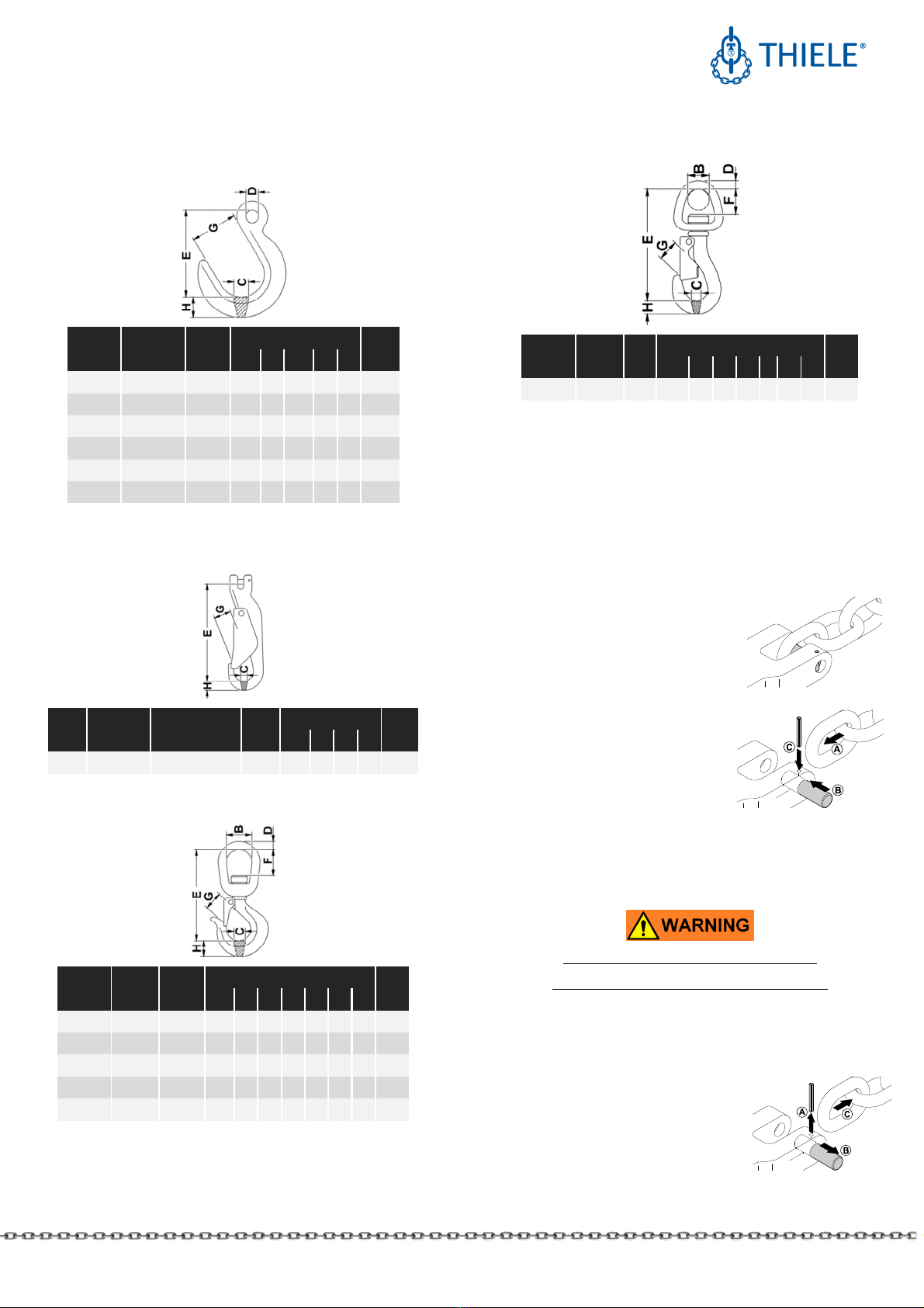
5.10 Lifting hook for engines,
TWN 0889, grade 80
Nom.
size Article no.
Nom. Diameter
[mm]
WLL
[lbs]
Dimensions [mm]
Mass
[lbs]
E G H C
1/4 F33439 6 1 100
137
19
13
12
1.21
5.11 S ivel hooks, TWN 0854, Grade 80
Nominal
size
Article
no.
WLL
[lbs]
Dimensions [mm]
Mass
[lbs
]
E G H
C F B D
1/4 F32103
2 500 114
18
20
14
25
30
10
0.84
5/1 F32103
4 500 155
21
25
19
42
44
16
2.20
13/8 F32103
7 100 162
23
30
21
42
44
16
2.65
1/2 F32103
12 000
190
32
33
28
43
51
19
4.63
5/8 F32103
18 100
247
40
43
35
61
64
25
9.92
5.12 S ivel hooks, TWN 0887, grade 80
Nominal
size [t]
Article
no.
WLL
[lbs]
Dimensions [mm]
Mass
[lbs]
E G H C D
F B
0.35 F32160
770 98.5
14
14
14
9
20
16
0.53
6. ASSEMBLY AND REMOVAL
6.1 Preparations
All components to be installed or used must be in perfect
condition and the relevant working load limits of all parts must
accommodate the respective load to be handled.
6.2 Clevis fastening system
The clevis fastening system only
permits attachment of the nominal
chain size that suits the attachment
component.
.2.1 ASSEMBLY
•If necessary, remove dowel pin
and pin.
•(A) Place end of chain leg
between the lateral clevis
elements.
•(B) Push pin from the side fully
into the clevis and through the last chain link of the leg.
•(C) Drive dowel pin fully in (must not project) to secure the
pin. The slot must face away from the pin.
Check whether the chain runs smoothly.
The dowel pins must only be installed once.
Only connect pins and attachment components of identical
grades. Starting with Ø ½” the pins are marked on the front end.
.2.2 DISASSEMBLY
•Slacken the respective chain leg.
•(A) Drive dowel pin out using
hammer and drift punch
1)
.
•(B) Push pin out using a drift punch.
•(C) Remove the chain.
Suitable drift punches are available by article no. Z03303.

MOUNTING INSTRUCTIONS
HOOKS GRADES 80 AND 100
THIELE GmbH & Co. KG # change indicator
www.thiele.de
| info@thiele.de B11090-C replaces B11090-B
All rights reserved. US 02.2022 6 | 7
6.3 Safety latch
Disassembly by driving the dowel pins out.
Assembling by correct positioning of safety latch together with
spring and driving in the thicker dowel pin by a hammer.
Afterwards the thinner dowel pin has to be driven in, taking care
that the slots positioned adverse. Check the correct operability
of the safety latch.
7. CONDITIONS OF USE
7.1 Normal use
Hooks must always be freely movable when attached to the load
and must not rest on or be supported by other structural parts.
When using hooks without safety ok, e.g. due to operational
necessities, special care is to be taken, and a separate risk
analysis must be prepared.
7.2 Influence of temperature
Using hooks at elevated temperatures will cause the working
load limit to be reduced as indicated below.
Grade Temperature range Remaining WLL
80
-40 °C ≤ t ≤ 205 °C
-40 °F ≤ t ≤ 400 °F 100 %
205 °C < t ≤ 300 °C
400 °F < t ≤ 572 °F 90 %
300 °C < t ≤ 400 °C
572 °F < t ≤ 752 °F 75 %
100 -40 °C ≤ t ≤ 205 °C
-40 °F ≤ t ≤ 400 °F 100 %
If a hook has been exposed to temperatures exceeding
the maximum values specified, it must not be used
furthermore.
7.3 Environmental influence
Hooks must not be used in environments where acids,
aggressive or corrosive chemicals or their fumes are present.
Hot-dip galvanizing or a galvanic treatment is prohibited.
Hooks with clevis are not intended to be used for abrasive
blasting environments.
8. SPARE PARTS
Use only original spare parts.
8.1 Spare part sets for clevis fastening system
Sets consist of pins and dowel pins.
Grade 80 Grade 100
Nominal
s
ize
Article no.
Nominal
s
ize
Article no.
1/4 F48694 1/4 F48686
5/1 F48352 5/1 F48687
3/8 F48355 3/8 F48688
1/2 F48358 1/2 F48689
5/8 F48361 5/8 F48690
3/4 F48369 - -
7/8 F48367 - -
8.2 Spare part sets safety latches
Sets consist of safety latch, spring and dowel pins.
Grade 80 Grade 100
TWN 0835/1
TWN 0858/1
TWN 1340/1
TWN 1835/1
TWN 1840/1
TWN 1841/1
Nominal
size Article no.
Nominal
size Article no.
1/4 F48730 1/4 F48731
5/1 F48732 5/1 F48733
3/8 F48734 3/8 F48735
1/2 F48736 1/2 F48737
5/8 F48738 5/8 F48739
3/4 F48742 7/8 F48745
7/8 F48744 1 on request
1 F48746 - -
1-¼ F48747 - -
MOUNTING INSTRUCTIONS
HOOKS GRADES 80 AND 100
THIELE GmbH & Co. KG # change indicator
www.thiele.de
| info@thiele.de B11090-C replaces B11090-B
All rights reserved. US 02.2022 7 | 7
9. INSPECTION, MAINTENANCE, DISPOSAL
Inspections and maintenance must be arranged by the owner!
Inspection intervals must be determined by the owner!
Visual inspections must be regularly carried out and
documented by competent and trained persons, at least once a
year or more frequently if the hooks are in heavy duty service.
After three years at the latest they must additionally be
examined for cracks. A load test is not a substitute for this
examination.
The results of the inspection shall be kept in a file that has to be
set up for each chain sling
#
before first use. The register shall
show characteristic data of the chain slings
#
and components as
well as identity details.
Immediately stop using hooks that show the following defects:
•missing or illegible identification/marking,
•deformation, elongation or fractures,
•cuts, notches, cracks, incipient cracks, pinching,
•heating beyond permissible limits,
•severe corrosion,
•broken springs,
•not sufficient working safety devices,
•wear in excess of 10 %, e.g. in the receiving area of the pin
diameter,
•missing or damaged pin locks or removal preventing guards.
Cleaning (e.g. prior to inspections) must not take place by using
flames or methods that might cause hydrogen embrittlement
(e.g. pickling or immersion in acidic solutions).
9.1 Inspection service
THIELE offers inspection, maintenance and repair services
performed by trained and competent personnel.
9.2 Maintenance
Maintenance and repair work must only be performed by
competent and trained persons.
Minor notches and cracks may be eliminated by careful grinding
observing the maximum cross section reduction requirement of
max. 10 % and avoid making more severe cuts or scores.
All maintenance and repair activities must be documented
properly.
9.3 Disposal
All steel components and accessories taken out of service must
be scrapped in accordance with local regulations and provisions.
10. STORAGE
Hooks must be stored properly sorted and in dry conditions at
temperatures between 32 °F and 104 °F.
Do not store in a manner that cause mechanical damage.
11. THIELE OPERATING AND MOUNTING
INSTRUCTIONS
Current mounting and operating instructions are available as a
PDF download on the THIELE-website www.thiele.de.
12. PUBLISHING INFORMATION
#
Company KWS Inc. THIELE GmbH & Co. KG
(Distributor) (Manufacturer)
Postal
address
P.O. Box 470487
Tulsa, OK 74147
USA
Werkstrasse 3
58640 Iserlohn
Germany
Phone
number +1 (539) 367 2274 +49 2371/947-0
Fax number +1 (539) 367 2278 +49 2371/947-241
This manual suits for next models
12
Table of contents
Other Thiele Industrial Equipment manuals

Thiele
Thiele TWN 0796 User manual

Thiele
Thiele TWN 0850/1 User manual

Thiele
Thiele TWN 0119 User manual

Thiele
Thiele Streamfeeder Value Series User manual

Thiele
Thiele TWN 0861 User manual

Thiele
Thiele TWN 0835/1 User manual

Thiele
Thiele TWN 0812 User manual

Thiele
Thiele TWN 1472 User manual

Thiele
Thiele Streamfeeder Reliant 3700 User manual

Thiele
Thiele Streamfeeder Reliant 3700 User manual


