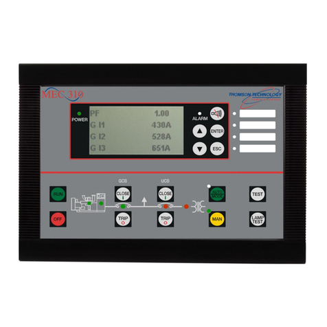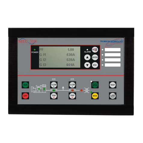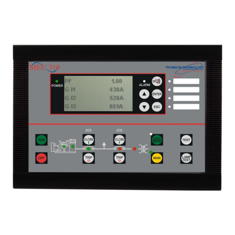
MEC 310 OPERATION MANUAL
PM089 Rev 0 08/11/24 Thomson Technology
9
4. Basic Operation
Basic Operational Theory
These operation instructions are based on the assumption the controller has been previously
determined that the programming has been reviewed, modified and the controls and engine
generator set commissioned as acceptable for it’s intended use. It is also assumed the engine
generator set is ready to operate and all necessary house keeping has been completed such
as, checking oil and coolant levels, all mechanical and electrical fundamentals proven to be in
good working order.
Initial Power up and Fault Clearing
On initial power up of the controller it is probable that various alarms or shutdowns may be presented.
These will need to be cleared prior to placing the equipment into service or operation.
Fault alarms can only be cleared if the alarm message appears on the display, the field device causing
the fault has returned to the non-fail state or the associated alarm is programmed to be ignored during
initial start up (bypassed on start) and the ENTER push-button depressed. If the field device remains in
its fault state during the reset process and its fault condition is not programmed to be ignored during initial
start up pressing the ENTER push-button will only result in acknowledging the alarm.
Shutdown states require the OFF push-button be depressed prior to the ENTER push-button to
allow fault clearing. This ensures the engine generator set cannot unintentionally restart after the
fault is cleared if an automatic start is being requested.
Previously acknowledged alarms or shutdowns will clear automatically when its associate field
device returns to its non-fail state.
Shutdown conditions differ from Alarm conditions in that only one shutdown can exist at a time, 1st
shutdown in locks out subsequent shutdowns. If multiple shutdowns were permitted it would be
impossible to determine which state was the actual cause making troubleshooting a nearly impossible
task.
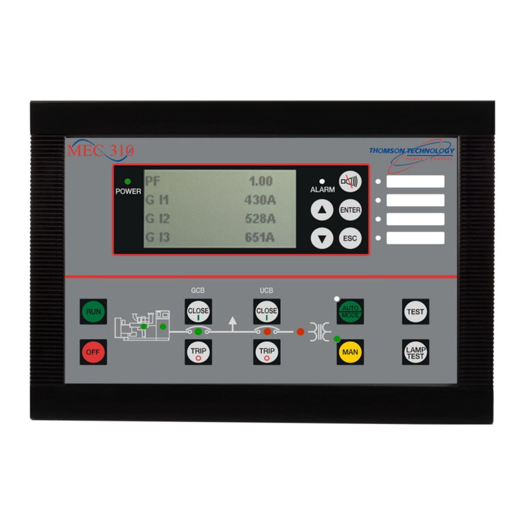
The controller provides a quick reference as to the alarm state level. The alarm LED on the controller can
change between an amber or red state. If both alarms and a shutdown are present the LED will be red
indicating the highest level of alarm, this being a shutdown condition. When there are only alarms
present, the alarm LED will be amber. Multiple alarms are permitted and will be displayed on the alarm
list with an up/down arrow advising to scroll through the list to view all. Only the displayed alarm can be
cleared, unviewed alarms cannot be cleared unless displayed or previously acknowledged.
A flashing alarm LED is an indication of a new alarm/shutdown, which is unacknowledged. Pressing the
ENTER push-button will acknowledge and/or clear the alarm if the associated field device or program
permits. If not permitted the alarm LED will change to a solid state, if multiple new alarms are present the
LED will continue to flash until all new alarms are acknowledged or cleared.
The Horn Silence push-button only silences the local controller horn and reset the horn relay
output, it will not acknowledge or clear alarm states. The MEC310 internal alarm horn must be
enabled using M-Logic if desired.
The Horn Silence push-button provides a secondary function, by holding this push-button for
greater than 2 seconds the alarm list is displayed.

