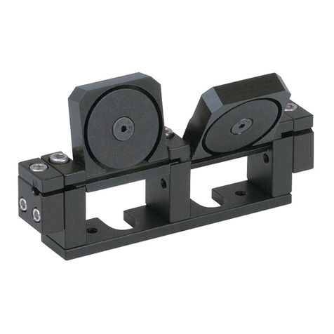
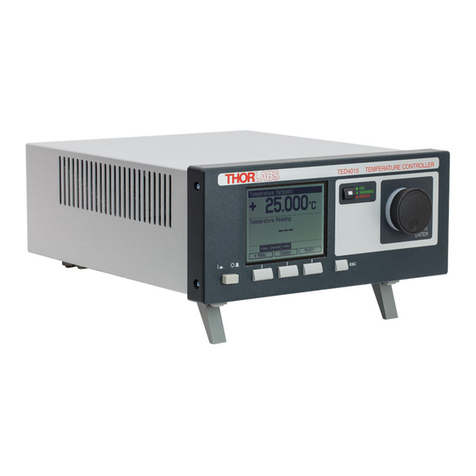
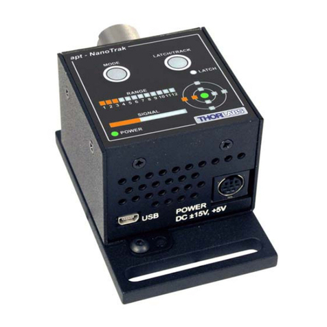
THORLABS APF503 User manual
Other THORLABS Controllers manuals
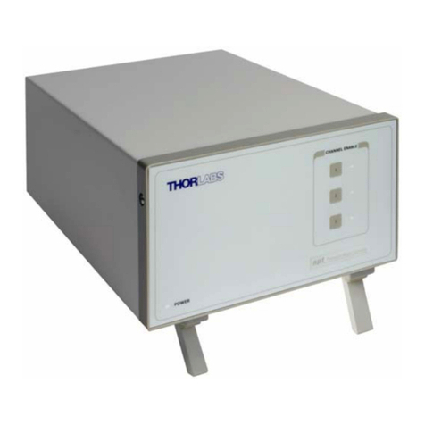
THORLABS
THORLABS BSC202 User manual
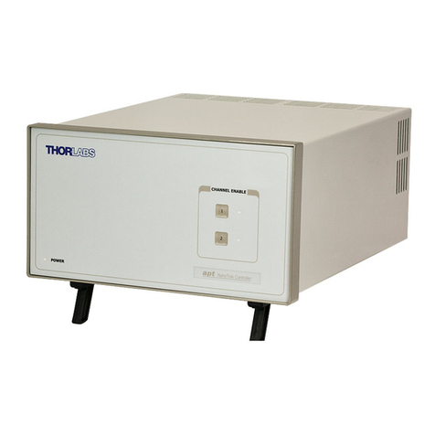
THORLABS
THORLABS BNT001/IR User manual
THORLABS
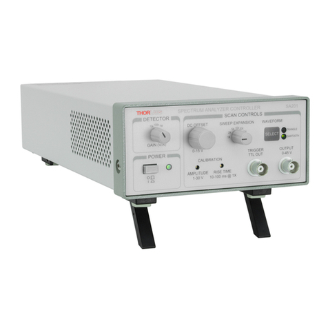
THORLABS SA201 User manual
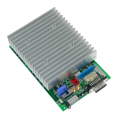
THORLABS
THORLABS ITC1 Series User manual
THORLABS
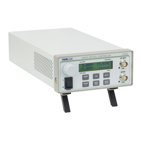
THORLABS LCC25 User manual
THORLABS
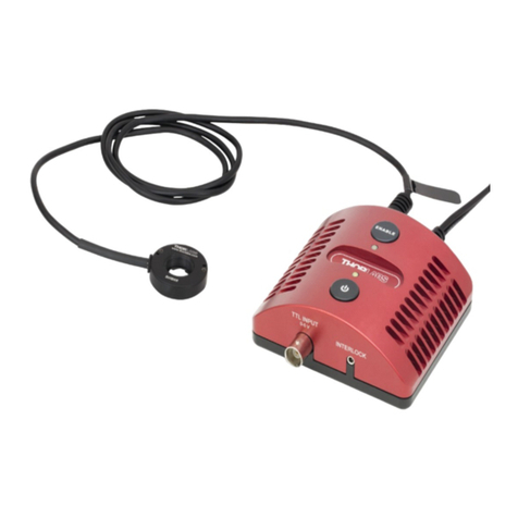
THORLABS SHB05 User manual
THORLABS
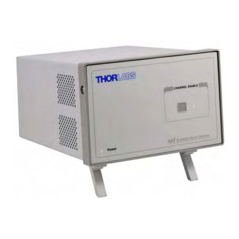
THORLABS BBD101 User manual
THORLABS
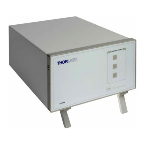
THORLABS BSC103 User manual
THORLABS
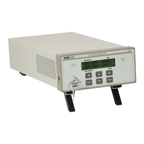
THORLABS SC10 User manual
THORLABS
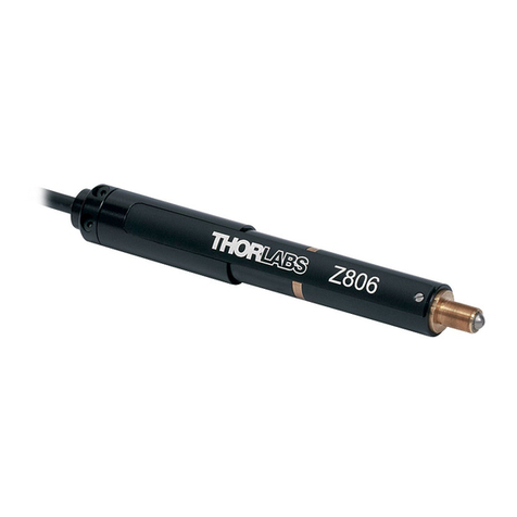
THORLABS Z8 Series User manual
THORLABS
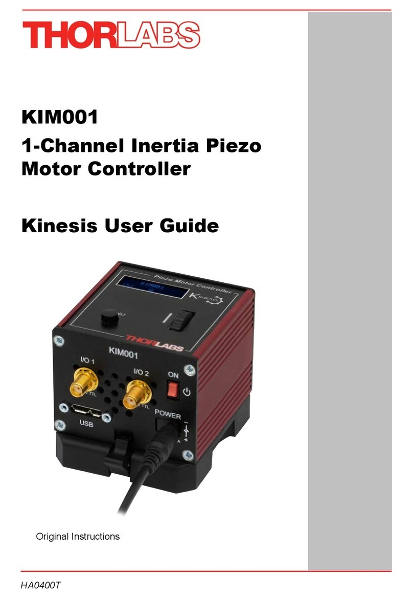
THORLABS KIM001 User manual
THORLABS
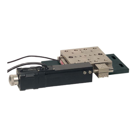
THORLABS LNR502E User manual
THORLABS
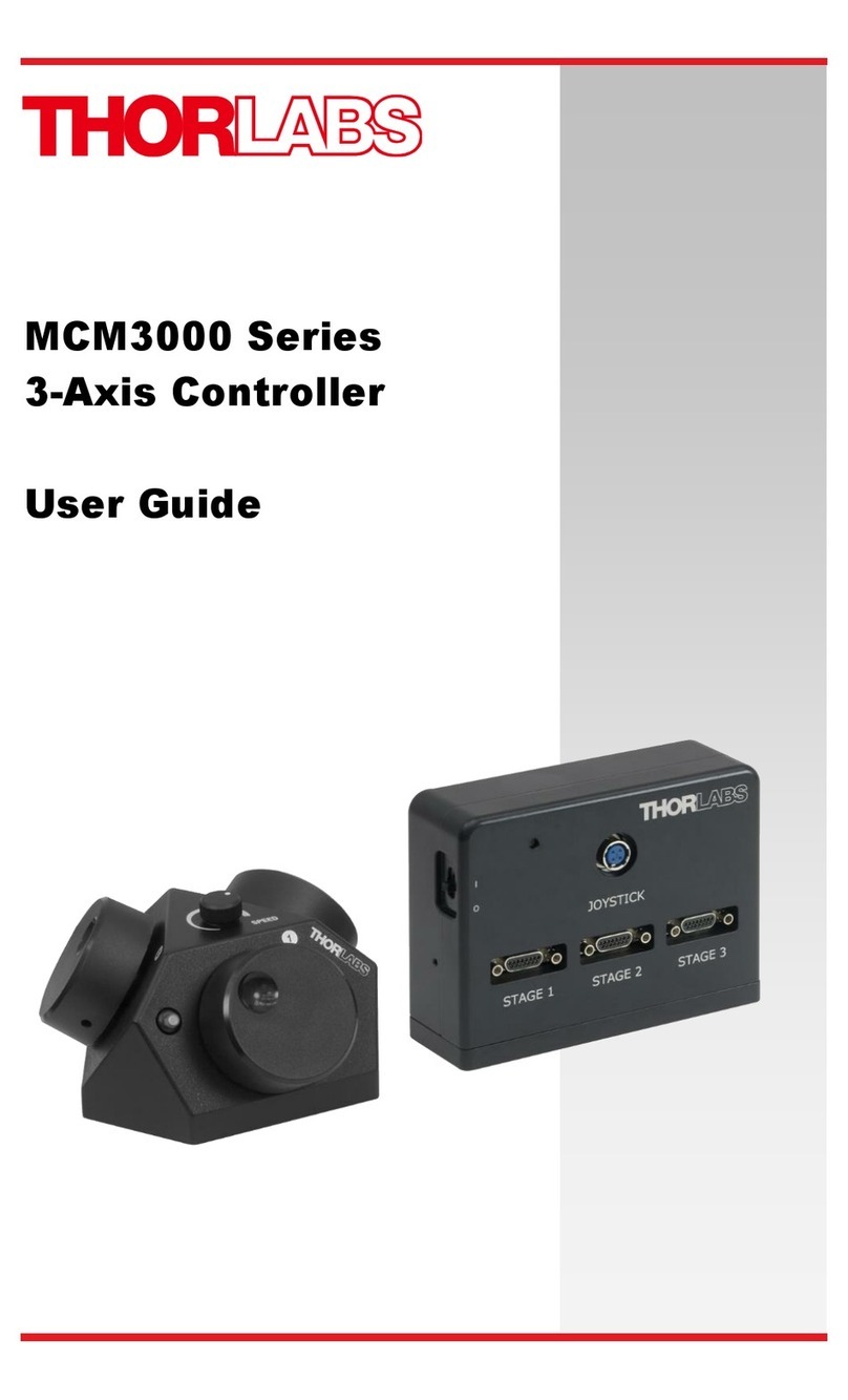
THORLABS MCM3000 Series User manual
THORLABS
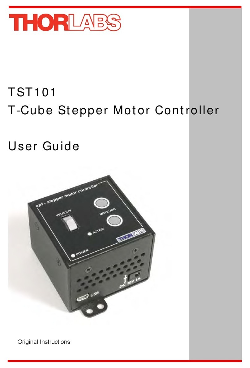
THORLABS TST101 User manual
THORLABS
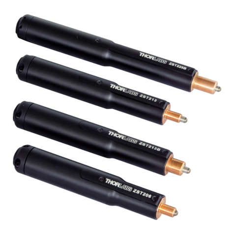
THORLABS ZST200 Series User manual
THORLABS
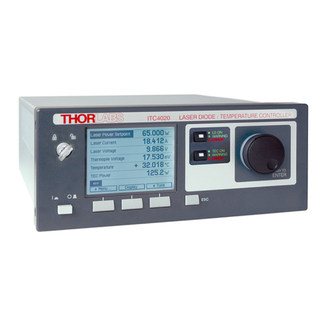
THORLABS ITC4000 Series User manual
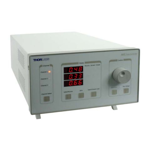
THORLABS
THORLABS BPC303 User manual
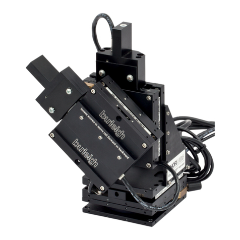
THORLABS
THORLABS PCS-6000 Series User manual
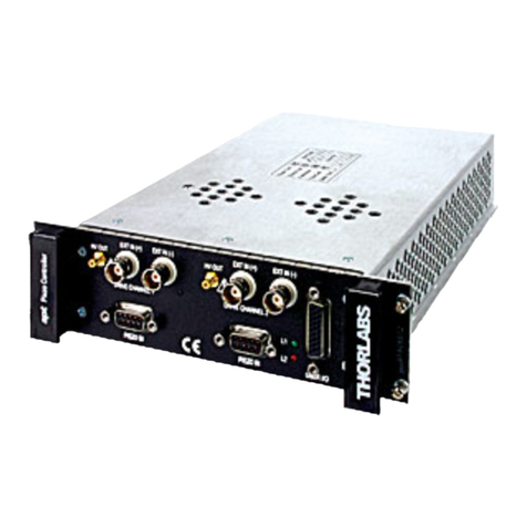
THORLABS
THORLABS MPZ601 User manual

THORLABS
THORLABS APT 600 User manual
Popular Controllers manuals by other brands

Digiplex
Digiplex DGP-848 Programming guide

YASKAWA
YASKAWA SGM series user manual

Sinope
Sinope Calypso RM3500ZB installation guide

Isimet
Isimet DLA Series Style 2 Installation, Operations, Start-up and Maintenance Instructions

LSIS
LSIS sv-ip5a user manual

Airflow
Airflow Uno hab Installation and operating instructions
