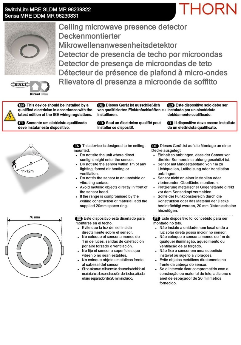
Thorn SENSA MRE SEND DSI Installation and operation manual

W4047H
Installation and Commissioning
Instructions
Note: SENSA SENP required for commissioning
At the end of their useful life
the packaging and product
should be disposed of via a
suitable recycling centre.
Do not dispose of with normal
household waste.
Do not burn.
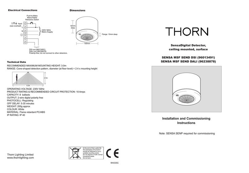
Electrical Connections
115mm
65mm
Supply
230V
50Hz
Push-to-Make
Mains-Rated
Retractive Switch
Brown
Blue
Orange
White
DSI out (96211279)
DALI out (96238877)
Polarity-free; do not connect to other detectors.
Red
L
N
Sensa Digital Detector,
ceiling mounted
SENSA MRE SEND DSI (96211279)
SENSA MRE SEND DALI (96238877)
Thorn Lighting Limited
www.thornlighting.com
T
Input
(see overleaf)
Technical Data
RECOMMENDED MAXIMUM MOUNTING HEIGHT: 3.0m
RANGE: Cone-shaped detection pattern, diameter (at floor level) = 2.4 x mounting height
OPERATING VOLTAGE: 230V 50Hz
PRODUCT RATING & RECOMMENDED CIRCUIT PROTECTION: 10 Amps
CAPACITY: 8 ballasts
OUTPUT: 2-wire digital polarity free-max extended cable length: 12m
PHOTOCELL: Regulating
OFF DELAY: 5-35 minutes
DEPTH REQUIRED BEHIND CEILING: 125mm
WEIGHT: 70g approx excluding cable
COLOUR: White
MATERIAL: Flame retardant PC/ABS
IP RATING: IP 40
6.0m
2.5m

SENSA MRE SEND DSI (96211279) &
Only suitably qualified personnel should install this equipment.
Fixing
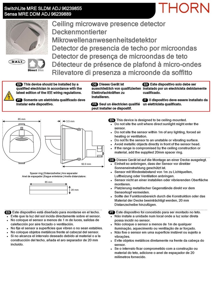
These detectors are suitable for flush fitting to a suspended ceiling of thickness up to 54mm. A minimum
clearance of 125mm is required between the front surface of the ceiling tile and the hard ceiling.
Choose a suitable mounting location; ideally this would be in the centre of the controlled lighting and as close
as possible to where occupants normally sit.
Cut a 50mm diameter circular hole in the tile. Feed the flying lead and detector through the hole and secure in
position with the locking ring. Twisting the locking ring will release the detector should this be necessary.
Note: Do not position within 25cm of a luminaire.
Connection
The detector is supplied with a flying lead which should be taken to the nearest 230V power supply. This lead
also contains connections for the polarity-free digital output (for connections to the control input on the ballast)
and dimming input. The dimming input is sheathed for applications which do not require this
connection. This wire should be terminated safely if not being used - do not connect to Neutral or Earth.
Please see below for details.
Control of a group of luminaires is achieved via the detector’s two-wire digital control circuit. Each luminaire to
be controlled must contain a digital regulating type ballast with the appropriate DSI input (for use with
96211279) or DALI input (for use with 96238877). Ballast types must not be mixed. Connect all ballasts in the
control group (max 8) in parallel and also to the polarity-free digital output of the detector.
Each luminaire is controlled completely by its digital input and therefore would normally have a permanent
power supply. If, however, it is desired to have manual wall switches, any or all of the fittings in a controlled
group may also be controlled in the traditional way - by turning off the power. The control circuit will continue to
operate properly even if some of the luminaires in the group have had mains power removed.
Dimming option
dimming affords local control to the end-user whereby a simple, momentary, push-to-make wallswitch
can be used to raise or lower the lighting level or to toggle the output ON/OFF. The momentary action switch is
connected between Live and the detector’s input. A short press of the switch (less than 1 second) will
toggle the output status while a longer press will raise or lower the output. Each time the switch is pressed, the
direction of dimming reverses. If the switch has not been pressed for 5 seconds, the direction will be up
(brighter) - unless the output is already above 90% in which case the direction is down. If the switch is held
continuously, and the output reaches maximum, the light output will remain at this level until the switch is
released - a latching switch may be connected in parallel allowing the occupancy detection to be overridden on
(Note: If the initial direction was down, when the output reaches minimum it will ramp back up automatically).
Several detectors may also be connected to one common momentary action switch in parallel - as long as all
detectors and the switch are powered from the same phase.
Setting the regulating photocell
This product is intended for use with high frequency regulating ballasts with DSI or DALI control inputs. An
infrared programming tool SENSA SENP (96004189) is required for programming the regulating light level set
point. The setting is preserved in the event of a power failure and can be re-programmed any number of times.
Use the ‘up’ and ‘down’ buttons to manually adjust the light output from the luminaire(s) and when at the required
level press and hold the ‘store’ button. The luminaire(s) will blink to acknowledge a successful store operation.
SENSA MRE SEND DALI (96238877) Commissioning
The factory default settings will be appropriate for most applications. However, the installer does have the facility
to re-programme a wide range of parameters and to set the regulating light level using the SENSA SENP
(96004189) infrared programming tool.
Please read carefully the operating instructions that accompany the programmer prior to performing a
programming operation.
Below is a table showing the pre-set factory settings and a brief explanation of each parameter.
These parameters may be re-programmed any number of times and all settings will be retained in the event of a
power loss.
W4047H
Important Additional Notes
1. A means for disconnection must be incorporated in the fixed wiring in accordance with the current wiring regulations.
2. Although nominally 12V, the dimming output is not ELV and therefore should be treated with the same respect as mains
with regard to wiring practice. The 0V line of the dimming output is almost at Neutral potential.
3. The dimming control output should be connected only to the control input of the ballasts - never to other detectors.
4. This equipment should be used to control only those ballasts powered from the same phase as the detector.
5. Due to the fact that the photocell is on the ceiling looking down, it is not possible for measurements made with a lux meter
on the working plane to remain constant when daylight illuminates the ceiling and the working plane to a differing extent.
Therefore, products of this type should be regarded as capable of maintaining an APPROXIMATE light level only.
6. This equipment switches lights no more frequently than would a responsible human occupant. However, for some
luminaires a maximum number of switching cycles is specified in order to achieve a predicted lamp life. Please refer to the
data sheets of the luminaires to ensure that they are compatible with automatic controls in this respect.
T
T
T
T
T
T
Parameter Options Pre-set Notes
Power up on/off on Sets the luminaire state at power up irrespective of occupancy. Useful in
reducing start-up load following power cut. Power-Up off - responds to
occupancy after 30 seconds.
Response auto/semi-auto auto If set to auto, the presence detector switches the luminaire on and off
automatically. If set to semi-auto, the luminaire will not turn on automatically
when a person enters the area. It can be turned on using the hand-held
controller or by toggling the power switch. When the area is vacated, the light
will turn off automatically.
Off delay 5 - 35 mins 20 mins The time for which the luminaire will stay on following the last detected
movement. Also 10 second setting for walk-testing.
Start lamps max/min max Sets the level at which the lamps strike when turning on.
Bright out yes/no no If set to yes, movement fails to refresh the off delay if the ambient light level
exceeds 125% of the set level, and the luminaire will switch off when the
the off delay has elapsed. (Note Dimming must be set to 100%.)
Fade to off yes/no no When no presence is detected, and after the off delay period, the lamps can
fade out instead of switching off (approx 80 seconds to fade from100% to 0%).
When vacant low/off / reg <25% off These are the options for a vacant area after it has timed out. Luminairescan
turn off, remain at minimum output, or regulate with a 25% output limit, until
the next period of occupancy. If programmed to remain at minimum or regulate
below 25%, there is a programmable option to switch off after 3 times the Off
delay.

W4047H
Instructions d'installation et de
mise en service
Note: SENSA SENP nécessaire pour la mise en
service
À la fin de leur durée de vie
utile, l'emballage et le produit
doivent être mis au rebut
auprès d'un centre de
recyclage approprié. Ne pas
jeter avec les ordures
ménagères. Ne pas brûler.
Connexions électriques
115mm
65mm
Alimentation
230 V
50Hz
Bouton poussoir
Brun
Bleu
Orange
Blanc
Sortie numérique DSI (96211279)
Sortie numérique DALI (96238877)
Sans polarité ; ne pas connecter à d'autres détecteurs.
Rouge
L
N
Détecteur Sensa Digital,
montage au plafond
SENSA MRE SEND DSI (96211279)
SENSA MRE SEND DALI (96238877)
Thorn Lighting Limited
www.thornlighting.com
Données techniques
HAUTEUR DE FEU MAXIMALE RECOMMANDÉE : 3,0 m max
PLAGE : schéma de détection en forme de cône, diamètre (au niveau du sol) = 2,4 x hauteur de feu
TENSION DE FONCTIONNEMENT : 230 V 50 Hz
PROTECTION DE CIRCUIT RECOMMANDÉ : 10 A
CAPACITÉ DE SORTIE : 8 ballasts
SORTIE : 2 câbles numériques sans polarité (longueur maximale du câble : 12 m)
CELLULE PHOTOÉLECTRIQUE : circuit de commande numérique
TEMPS D'EXTINCTION : 5 – 35 min
PROFONDEUR NÉCESSAIRE DERRIÈRE LE PLAFOND : 125 mm
POIDS : 70 g sans le câble
COULEUR : blanc
MATÉRIAU : PC/ABS retardateur de flamme
ÉTANCHÉITÉ IP : IP40
6.0m
2.5m
Entrée T↑↓
(voir verso)

SENSA MRE SEND DSI (96211279) &
L'installation de cet équipement ne doit être confiée qu'à des personnes qualifiées.
Fixation
Le détecteur peut être encastré dans un faux-plafond d'une épaisseur maximale de 54 mm. Une distance
minimale de 125 mm est nécessaire entre la surface extérieure de la dalle du faux-plafond et le plein plafond.
Choisissez un emplacement approprié. Dans l'idéal, il doit être monté au centre de la zone contrôlé et aussi près
que possible de l'endroit où les occupants s'assoient en général.
Découpez un orifice circulaire de 50 mm de diamètre dans la dalle. Faites passer le câble et le détecteur par
l'orifice et fixez-le à l'aide de l'anneau de fixation. Si nécessaire, il suffit de faire tourner l'anneau de fixation pour
libérer le détecteur.
Note: ne pas placer à moins de 25 cm du luminaire.
Raccordement
Le détecteur est fourni avec un câble devant être connecté à l'alimentation 230 V la plus proche. Ce câble
comprend également des connexions pour la sortie numérique sans polarité (pour les connexions à l'entrée de
commande du ballast) et l'entrée de gradation T↑↓. L'entrée de gradation T↑↓ est gainée pour les applications
ne nécessitant pas cette connexion. S'il n'est pas utilisé, ce câble doit être sécurisé - ne pas raccorder à un
conducteur neutre ou à la va terre. Veuillez vous reporter ci-dessous pour plus de détails sur T↑↓.
Le contrôle d'un groupe de luminaires s'effectue à l'aide du circuit de commande numérique du détecteur.
Chaque luminaire à commander doit être doté d'un ballast à gradation numérique DSI (avec 96211279) ou DALI
(avec 96238877). Une mélange des ballasts DSI et DALI est interdit. Connectez en parallèle tous les ballasts du
groupe de commande (maximum 8) ainsi qu'à la sortie numérique sans polarité du détecteur.
Chaque luminaire est intégralement contrôlé par son entrée numérique. C'est pourquoi il doit normalement
disposer d'une alimentation électrique permanente. Toutefois, si des interrupteurs muraux manuels sont
demandés, tout ou partie des appareils d'un groupe contrôlé peuvent également être commandés de manière
traditionnelle, c'est-à-dire en coupant l'alimentation. Le circuit de commande va continuer à fonctionner
correctement même si l'alimentation secteur de certains luminaires du groupe a été coupée.
Option de gradation T↑↓
La gradation T↑ ↓ permet un contrôle local par l'utilisateur final, à l'aide d'un bouton poussoir qui peut servir à
augmenter ou diminuer le niveau d'éclairage ou à allumer/éteindre la sortie. Le bouton poussoir est raccordé
entre le conducteur sous tension et l'entrée T↑↓ du détecteur. Pour modifier le statut de sortie, il suffit d'appliquer
une courte pression sur le bouton poussoir (moins d'une seconde). Une pression plus longue permettra
d'augmenter ou diminuer le flux. Chaque pression sur le bouton poussoir modifie le sens de la gradation. Si
l'appui n'a pas duré 5 secondes, la gradation augmente (plus lumineux), à moins que le rendement ne soit déjà
supérieur à 90 %. Dans ce cas, la gradation diminue. Si la pression sur le bouton poussoir est continue et que le
flux lumineux atteint son niveau maximum, le rendement lumineux reste à ce niveau jusqu'à ce que le bouton
poussoir soit relâché. Un commutateur de verrouillage peut être connecté en parallèle afin de prendre le pas sur
le détecteur de présence (Remarque : si la gradation diminuait au départ, le flux automatiquement repartir dans
l'autre sens après avoir atteint son minimum). Plusieurs détecteurs peuvent également être connectés en
parallèle à un bouton poussoir, du moment que les détecteurs et l'interrupteur fonctionnement tous sur la même
phase.
SENSA MRE SEND DALI (96238877) Mise en service
Le paramétrage par défaut conviendra à la plupart des applications. Toutefois, l'installateur a la possibilité de
reprogrammer un large éventail de paramètres et de définir le réglage du niveau d'éclairement à l'aide de l'outil
de programmation infrarouge SENSA SENP (96004189).
Veuillez lire attentivement les instructions de fonctionnement fournies avec le programmateur avant toute
programmation.
Vous trouverez ci-dessous un tableau présentant le paramétrage par défaut ainsi qu'une explication succincte de
chaque paramètre. Ces paramètres peuvent être reprogrammés autant de fois que nécessaire. De plus, ces
paramètres sont mémorisés, en cas de coupure de l'alimentation.
W4047H
Remarques supplémentaires importantes
1. Un moyen de déconnexion doit être intégré au câblage fixé, conformément aux normes de câblage en vigueur.
2. Bien que la tension nominale de la sortie de gradation soit de 12 V, il ne s'agit pas d'une basse tension. Lors du câblage, elle
doit donc être considérée comme une tension secteur. La ligne 0V de la sortie de gradation est pratiquement en potentiel
neutre.
3. La sortie de commande de gradation doit uniquement être connectée à l'entrée de commande des ballasts et jamais aux
autres détecteurs.
4. Cet équipement ne doit être utilisé que pour contrôler des ballasts fonctionnant sur la même phase que le détecteur.
5. Étant donné que la cellule photoélectrique est montée au plafond et qu'elle est dirigée vers le bas, les mesures réalisées à
l'aide d'un luxmètre sur le plan de travail ne peuvent pas être constantes lorsque la lumière du jour éclaire différemment le
plan de travail et le plafond. C'est pourquoi les produits de ce type ne doivent être considérés que comme des produits à
même de maintenir un niveau d'éclairement APPROXIMATIF.
6. Ce produit n'allume/n'éteint pas les lampes plus souvent qu'une utilisation avec un interrupteur traditionnel. Toutefois, un
nombre maximum de cycles d'allumage/extinction est spécifié pour certains luminaires afin de connaître la durée de vie
prévue de la lampe. Veuillez vous reporter aux fiches techniques des luminaires afin de vous assurer qu'ils sont bien
compatibles avec les commandes automatiques.
Remarques
Etat du luminaire lors d'une remise sous tension (suite coupure réseau).
Mode de fonctionnement si détection de présence :
Automatique signifie que le système réagit de façon autonome.
Semi-automatique signifie que seule l'extinction est automatique lors de
l'absence de mouvements. La détection est inhibée, seule la télécommande
ou un poussoir sur l'alimentation de la cellule permet le réallumage
Période après le dernier mouvement pour déclencher l'extinction ou la gradation
du système. Mini = 10s pour test.
Niveau lumineux lors du réallumage : maxi puis décroissant ou mini puis
croissant.
OUI : Inhibition possible de la détection de présence si l'apport de lumière
naturelle est trop important. L'appareil peut s'éteindre si 125% du flux est atteint.
Si NON le niveau lumineux reste au mini du ballast.
Extinction brutale (NON). Possibilité de diminuer jusqu'à l'extinction en 80
secondes (OUI).
Possibilités :
Les lumières s'éteignent.
Le flux lumineux reste au minimum pendant 3 x la durée programmée du
"RETARDATEUR" puis se coupe.
Le flux lumineux reste au minimum jusqu'a la prochaine occupation.
L'éclairage se régule en dessous de 25% pendant 3 x la durée programmée du
"RETARDATEUR" puis se coupe.
L'éclairage se régule en dessous de 25% jusqu'à la prochaine occupation.
Paramètre
MISE SOUS
TENSION
DÉTECTEUR DE
MOUVEMENT
FONCTIONNEMENT
RETARDATEUR
DÉMARRAGE
BRILLANCE
DIMINUTION
JUSQU'À
EXTINCTION
OPTIONS À LA FIN
DU DÉLAI DU
RETARDATEUR
Options
MARCHE : allumé
ARRÊT : éteint
AUTOMATIQUE /
SEMI-AUTOMATIQU
de 5 à 35 min
AU MAXIMUM /
FAIBLE
OUI / NON
OUI / NON
AU MINIMUM /
EXTINCTION /
REGULATION <25 %
Par défaut
MARCHE
AUTOMATIQUE
20 min
AU MAXIMUM
NON
NON
EXTINCTION
Le paramétrage du niveau d'éclairement
Le niveau lumineux est réglable entre 0 et 100% du flux du luminaire. L'installateur a la possibilité de définir le
réglage du niveau d'éclairement à l'aide de l'outil de programmation infrarouge SENSA SENP (96004189) :
Réglage par les 3 boutons rouges de la télécommande.
Si OK envoi par la touche STORE.
W4047H
Installationsanvisningar
Obs! SENSA SENP krävs för montering
I slutet av sin användbara
livslängd ska
förpackningsmaterial och
produkt återvinnas på lämpligt
sätt.
Får inte kastas ut med vanligt
hushållsavfall.
Electrical Connections
115mm
65mm
Drift
230 V
50Hz
Potentialfri strömbrytare
med märkspänning och
återfjädring
Brun
Blå
Orange
Vit
DSI utgång (96211279)
DALI utgång (96238877).
Polaritetsfri; anslut inte till andra detektorer.
Röd
L
N
Sensa Digital detektor,
takmonterad
SENSA MRE SEND DSI (96211279)
SENSA MRE SEND DALI (96238877)
Thorn Lighting Limited
www.thornlighting.com
Teknisk information
REKOMMENDERAD MAXIMAL MONTERINGSHÖJD: 3,0 m max
UTBUD: Konformat avkänningsområde, diameter (på golvnivå) = 2,4 x monteringshöjd
DRIFTSSPÄNNING: 230 V 50 Hz
RECOMMENDED CIRCUIT PROTECTION: 10A
UTKAPACITET: 8 DSI HF-don
UTEFFEKT: Polaritetsfri med två ledningar (max utdragen kabellängd: 12 m)
PHOTOCELL: Regulating
TIDSINTERVAL: 5-35 minuter
KRÄVT DJUP BAKOM TAK: 125 mm
VIKT: 70 g
FÄRG: Vit
MATERIAL: Brandhärdig PC/ABS
KAPSLINGSKLASS: IP40
6.0m
2.5m
T↑↓-ingång
(se ovanstående sida)

SENSA MRE SEND DSI (96211279) &
Denna utrustning måste installeras av kvalificerad servicetekniker.
Montering
Detektorn är lämplig för inbyggnad i tak med en tjocklek på upp till 54 mm. Ett fritt utrymme på minst 125 mm
krävs mellan takpanelens framsida och cement taket.
Välj en lämplig monteringsplats, helst i mitten av rummet och så nära som möjligt den plats där personer
normalt sitter.
Bor ut ett runt hål på 50 mm i diameter i panelen. Montera detektorn genom hålet och fastgöras med låsringen.
Man kan vid behov avlägsna detektorn genom att skruva på låsringen.
Obs: Montera inte inom 25 cm från en armatur.
Inkoppling
Detektorn levereras med ett kabel som ska anslutas till närmaste 230 V tillslutning. Denna kabel har också
anslutningar för den polaritetsfria digitala utgången (för anslutning till styringången på HF-donet) och T↑ ↓ -
dimmeringången. Denna ledning ska avslutas på ett säkert sätt om den inte används.
Styrning av en grupp armaturer sker via detektorns digitala styrkrets med två ledningar. Varje armatur som ska
styras måste innehålla en digital-reglerande HF-don med lämplig DSI-ingång (med 96211279) eller DALI-
ingång (med 96238877). Anslut alla HF-don i styrgruppen (max 8) parallellt till detektorns polaritetsfria digitala
utgång.
Varje armatur styrs helt av dess digitala ingång och har därför normalt permanent strömförsörjning. Om
manuella väggkontakter önskas kan en eller flera av armaturerna i en styrd grupp också styras på traditionellt
sätt – genom att man stänger av strömmen. Styrkretsen fortsätter att fungera även om vissa armaturer i
gruppen inte är anslutna till huvudströmmen.
T↑↓Dimmeralternativ
T↑↓-dimning gör att slutanvändaren kan styra belysningen manuell. En enkel strömbrytare kan användas för
att reglera ljusnivån eller tända/släcka belysningen. Tryckbrytaren ansluts mellan strömförande anslutning
(live) och detektorns T↑↓-ingång. En kort tryckning på brytaren (mindre än 1 sekund) växlar mellan tänd/släck
och en längre tryckning höjer eller sänker belysningsnivån. Varje gång man trycker på brytaren ändras
riktningen på dimningen. Om man inte har tryckt på brytaren i 5 sekunder är riktningen upp (ljusare) – såvida
inte ljusstyrkan redan är över 90 %. Om detta är fallet är riktningen nedåt. Om man håller ner brytaren och
ljusstyrkan når max, blir ljusstyrkan kvar på denna nivå tills brytare släpps – en vanlig brytare kan anslutas
parallellt så att närvaroavkänning kan överstyras (Obs! Om ursprungsriktningen var ner växlar den
automatiskt till upp när ljusstyrkan når minimum). Flera detektorn kan också parallellanslutas till en enda
tryckbrytare – under förutsättning att alla detektorer och brytaren drivs från samma fas.
Inställning automatiska regleringsnivån
Kan ställas in för alla Belysningsnivå inom installationens (1-100%), med det infraröda
programmeringsverktyget SENSA SENP (96004189).
SENSA MRE SEND DALI (96238877) Idriftsättning
Fabriksinställningarna passar för de flesta ändamål. Montören kan emellertid programmera om en rad olika
parametrar och ställa in den automatiska regleringsnivån med det infraröda programmeringsverktyget SENSA
SENP (96004189).
Läs noga igenom användningsanvisningarna för verktyget innan du börjar programmera.
I nedanstående tabell visas de förinställda fabriksinställningarna och en kort förklaring av varje parameter. Dessa
parametrar kan programmeras om ett oändligt antal gånger, och alla inställningar bevaras vid ström avbrott.
W4047H
Viktig tilläggsinformation
1. Det måste finnas ett sätt att stänga av strömmen i den fasta kabeldragningen enligt kabeldragningsföreskrifterna.
2. Trots att dimnings utgången nominellt är 12 V, är den inte ELV och ska därför hanteras med samma respekt som
huvudström vad gäller kabeldragning. Dimmerutgångens 0V-ledning är nästan neutral potential.
3. Dimmerstyrningens utgång ska endast anslutas till styrutgången på HF-donen – aldrig till andra detektorer.
4. Denna utrustning ska endast användas för styrning av de HF-don som drivs från samma fas som detektorn.
5. På grund av att fotocellen sitter i taket och är riktad nedåt, är det inte möjligt för mätningar som är gjorda med en luxmätare
på arbetsplanet att vara konstant när dagsljus belyser taket och arbetsplanet med varierande nivå. Därför ska produkter av
denna typ endast anses kunna bibehålla en UNGEFÄRLIG belysningsnivå.
6. Denna utrustning tänder/släcker inte belysningen oftare än en ansvarsfull person. Men för vissa armaturer specificeras ett
maximalt antal tänd/släck cyklusser som åstadkommer belysningskällans förväntade livslängd. Läs armaturernas
datablad för att kontrollera att de är kompatibla med automatiska styrsystem i detta avseende.
Anmärkningar
Ställer in belysningen på uppstart oavsett närvaro. Uppstart av –
reagerar på närvaro efter 30 sekunder.
Om auto är inställt tänder/släcker närvarodetektorn armaturen
automatiskt. Om semiauto är inställt tänds armaturen inte
automatiskt när en person kommer in i rummet. Armaturen kan
tändas med fjärrkontrollen SENSA SENRC (96004175) eller genom
ett tryck på strömbrytaren. Ljuset släcks automatiskt när alla
personer lämnar rummet.
Tiden som armaturen är tänd efter den senast detekterade rörelsen.
Även 10 sekunders inställning för gångtest.
Ställer in styrkan på ljuskällorna när ljuset tänds.
Om ja är inställt och fotocellen registrerar en belysningsstyrka 125 %
över det inställda nivån, släcks i förhållande till den inställt tid
(närvaro)
När ingen närvaro detekteras, kan ljuskällorna reglera ner istället för
att släckas (ungefär 80 sekunders nedtoning från 100 % till 0 %).
Inställning för närvarodetektering . Armaturer kan stängas av, ha
minimal ljusstyrka eller ha en belysningsgräns på
25 % tills nästa person kommer in i rummet. Om armaturen är
programmerad till minimum eller en nivå under 25 % finns det ett
programmerbart alternativ för släckning av ljuset efter 3 timmar.
Paramètre
Uppstart
Närvaro
Tidsinterval
Uppstartsnivå
Fotocell/ skumring
Reglera till släck
Inställning av
närvarodetektor
Alternativ
på/av
auto/
semiauto
5 - 35 minuter
max/min
ja/nej
ja/nej
låg/av / regl. <25 %
Förinställning
på
auto
20 minuter
max
nej
nej
av
This manual suits for next models
1
Table of contents
Languages:
Other Thorn Security Sensor manuals

Thorn
Thorn SwitchLite MRE SLDM MR User manual

Thorn
Thorn MOVU MLE User manual

Thorn
Thorn SwitchLite MRE SLD User manual

Thorn
Thorn SwitchLite SLD BATTEN 96601988 User manual

Thorn
Thorn SWITCHLITE MRE SLDD PC User manual

Thorn
Thorn SENSA MSF SEND DSI Installation and operation manual

Thorn
Thorn SensaLite SLOCS Installation and operation manual

Thorn
Thorn ADJ 96239855 User manual

Thorn
Thorn SwitchLite MRE SLDM ADJ User manual

Thorn
Thorn SwitchLite SLDM 96019208 User manual