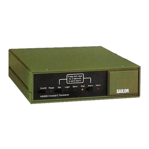
Thrane&Thrane TT-3020C User manual

Maritime CapsatTransceiver
TT-3020C
Installation Manual


Thrane & Thrane
Thrane & ThraneThrane & Thrane
Thrane & Thrane
Maritime CapsatTransceiver
TT-3020C
Installation Manual
CopyrightThrane & Thrane A/S
ALL RIGHTS RESERVED

Information in this document is subject to change without notice
and does not represent a commitment on the part of Thrane &
Thrane A/S.
© 2000 Thrane & Thrane A/S. All right reserved. Printed in Den-
mark.
Document Number TT98-107880-C.
Release Date: 25. July 2000

Safety Summary
Safety SummarySafety Summary
Safety Summary
The following general safety precautions must be observed during all phases of
operation, service and repair of this equipment. Failure to comply with these
precautions or with specific warnings elsewhere in this manual violates safety
standards of design, manufacture and intended use of the equipment.
Thrane & Thrane A/S assumes no liability for the customers failure to comply with
these requirements.
GROUND THE EQUIPMENT
GROUND THE EQUIPMENTGROUND THE EQUIPMENT
GROUND THE EQUIPMENT
To minimise shock hazard, the equipment chassis and cabinet must be connected to
an electrical ground
DO NOT OPERATE IN AN EXPLOSIVE ATMOSPHERE
DO NOT OPERATE IN AN EXPLOSIVE ATMOSPHEREDO NOT OPERATE IN AN EXPLOSIVE ATMOSPHERE
DO NOT OPERATE IN AN EXPLOSIVE ATMOSPHERE
Do not operate the equipment in the presence of flammable gases or fumes. Opera-
tion of any electrical equipment in such an environment constitutes a definite safety
hazard.
KEEP AWAY FROM LIVE CIRCUITS
KEEP AWAY FROM LIVE CIRCUITSKEEP AWAY FROM LIVE CIRCUITS
KEEP AWAY FROM LIVE CIRCUITS
Operating personnel must not remove equipment covers. Component replacement
and internal adjustment must be made by qualified maintenance personnel. Do not
replace components with the power cable connected. Under certain conditions,
dangerous voltages may exist even with the power cable removed. To avoid injuries,
always disconnect power and discharge circuits before touching them.
DO NOT SERVICE OR ADJUST ALONE
DO NOT SERVICE OR ADJUST ALONEDO NOT SERVICE OR ADJUST ALONE
DO NOT SERVICE OR ADJUST ALONE
Do not attempt internal service or adjustments unless another person, capable of
rendering first aid resuscitation, is present.
DO NOT SUBSTITUTE PARTS OR MODIFY EQUIPMENT
DO NOT SUBSTITUTE PARTS OR MODIFY EQUIPMENTDO NOT SUBSTITUTE PARTS OR MODIFY EQUIPMENT
DO NOT SUBSTITUTE PARTS OR MODIFY EQUIPMENT
Because of the danger of introducing additional hazards, do not substitute parts or
perform any unauthorized modification to the equipment.
SAFETY DISTANCE FOR THE ANTENNA UNIT
SAFETY DISTANCE FOR THE ANTENNA UNITSAFETY DISTANCE FOR THE ANTENNA UNIT
SAFETY DISTANCE FOR THE ANTENNA UNIT
Minimum safety distance of 2 feet (61 cm) from the Antenna.
Radiated intensity at 0.56m is 10 W/m2
Radiated intensity at 0.36m is 25 W/m2
Radiated intensity at 0.18m is 100 W/m2
COMPASS SAF
COMPASS SAFCOMPASS SAF
COMPASS SAFE DISTANCE
E DISTANCEE DISTANCE
E DISTANCE
Minimum safety distance of 50 cm from the TT-3020C transceiver

This page is intentionally left blank

Table of Contents
Table of ContentsTable of Contents
Table of Contents
25-Jul-00
25-Jul-0025-Jul-00
25-Jul-00 Page
PagePage
Page i
ii
i
Table of Contents
1 Introduction....................................................................................... 1-1
1.1 Initial Inspection ....................................................................... 1-1
1.2 Storage ..................................................................................... 1-2
1.3 Repackaging for shipment........................................................ 1-2
2 Installation - TT-3020C....................................................................... 2-1
2.1 Technical specifications............................................................ 2-1
2.2 Compass Safe Distance............................................................. 2-3
2.3 Power requirements ................................................................ 2-4
2.3.1 Fuse ............................................................................ 2-4
2.4 Functional description .............................................................. 2-4
2.4.1 On/Off features ........................................................... 2-4
2.4.2 Front indicators and buttons........................................ 2-5
2.5 Connectors ............................................................................... 2-7
2.5.1 Power connector ......................................................... 2-7
2.5.2 DTE Communication port ............................................ 2-9
2.5.3 I/O Connector........................................................... 2-11
2.5.4 Printer port................................................................ 2-15
2.5.5 Grounding ................................................................ 2-17
2.6 Built-in GPS (optional) ............................................................ 2-17
2.6.1 GPS specifications..................................................... 2-18
2.7 Mounting bracket ................................................................... 2-18
3 System Installation............................................................................. 3-1
3.1 Power requirements ................................................................ 3-1
3.1.1 Fuses........................................................................... 3-2
3.2 Compass Safe Distance............................................................. 3-3
3.3 Antennas................................................................................... 3-5
3.3.1 TT-3005M Maritime Antenna ....................................... 3-5
3.3.2 TT-3005A Maritime Antenna...................................... 3-10
3.3.3 TT-3001B Maritime Antenna ...................................... 3-15
3.3.4 Antenna Mounting Considerations ............................ 3-18
3.3.5 Safety Distance for Antenna Units.............................. 3-21
3.4 TT-3606E Message Terminal................................................... 3-23
3.4.1 Connectors................................................................ 3-23
3.4.2 TT-3601E keyboard................................................... 3-25
3.4.3 Specifications............................................................ 3-26
3.4.4 Mounting................................................................... 3-27

Table of Contents
Table of ContentsTable of Contents
Table of Contents
Page
PagePage
Page ii
iiii
ii 25-Jul-00
25-Jul-0025-Jul-00
25-Jul-00
3.5 TT-3680B Power Supply...........................................................3-29
3.5.1 Mounting ...................................................................3-29
3.6 TT-3608A Hard Copy Printer ...................................................3-31
3.6.1 Mounting plate...........................................................3-32
3.6.2 Roll Paper Stand.........................................................3-32
3.6.3 Mounting ...................................................................3-34
3.7 TT-3608G Printer Unit..............................................................3-35
3.7.1 Configuration.............................................................3-36
3.7.2 Installation .................................................................3-38
3.7.3 Connectors ................................................................3-38
3.7.4 Cable.........................................................................3-39
3.7.5 Specifications.............................................................3-41
3.8 TT-3042C Remote Alarm/Distress Box (optional) ....................3-42
3.8.1 Mounting ...................................................................3-45
3.9 TT-3042D Remote Alarm / Printer Unit ....................................3-48
3.9.1 Configuration.............................................................3-49
3.9.2 Installation .................................................................3-52
3.9.3 Connectors ................................................................3-52
3.9.4 Cable.........................................................................3-53
3.9.5 Specifications.............................................................3-55
3.10 Distress Button Test .................................................................3-56
3.10.1 TT-3020C Transceiver................................................3-56
3.10.2 TT-3042C Remote Alarm/Distress Box .......................3-57
3.10.3 TT-3042D Remote Alarm Distress Box........................3-57
3.11 General interconnect information ...........................................3-58
4 System Generation.............................................................................4-1
4.1 Terminal Mode..........................................................................4-1
4.1.1 TT-3606E Message Terminal........................................4-1
4.1.2 Computerised equipment/handheld terminals............4-1
4.2 Initialise System Parameters......................................................4-2
4.2.1 Entering your mobile number......................................4-2
4.2.2 Altering baudrate and protocol settings ......................4-3
4.2.3 Antenna voltage settings..............................................4-4
5 Commissioning ..................................................................................5-1
5.1 Introduction...............................................................................5-1
5.2 The first Login ...........................................................................5-1
5.3 Link Test....................................................................................5-2
5.4 Details of a Link Test..................................................................5-2
6 Index..................................................................................................6-1
Table of Figures
Table of FiguresTable of Figures
Table of Figures
25-Jul-00
25-Jul-0025-Jul-00
25-Jul-00 Page
PagePage
Page iii
iiiiii
iii
Table of Figures
Figure 1 TT-3020C Maritime Capsat Transceiver ........................................ 1-1
Figure 2TT-3020C Capsat Transceiver rear panel ....................................... 2-7
Figure 3 TT-3020C Capsat Transceiver mounting plate............................. 2-19
Figure 4 Front panel of the TT-3020C Capsat Transceiver with
mounting bracket ...................................................................................... 2-19
Figure 5 TT-3005M Maritime Antenna ......................................................... 3-5
Figure 6 TT-3005M 1’’ Tube Mounting ......................................................... 3-9
Figure 7 TT-3005A Maritime Antenna ........................................................ 3-10
Figure 8 TT-3005A 1.5’’ tube mounting...................................................... 3-14
Figure 9 TT-3001B opt. 001 Maritime Antenna........................................... 3-15
Figure 10 TT-3001B-opt. 001 1.5’’ Tube mounting...................................... 3-18
Figure 11 Inmarsat-C Antenna Mounting ................................................... 3-20
Figure 12 Inmarsat-C Antenna mounting near pole or funnel .................... 3-21
Figure 13 TT-3606E Message Terminal...................................................... 3-23
Figure 14 TT-3606E Rear Connectors ........................................................ 3-24
Figure 15 Mounting holes for TT-3606E ..................................................... 3-27
Figure 16 TT-3606E Mounting Bracket....................................................... 3-28
Figure 17 TT-3680B - 200W power supply. ................................................ 3-29
Figure 18 Mounting holes for TT-3680B ..................................................... 3-30
Figure 19 TT-3608A Hard copy printer ...................................................... 3-31
Figure 20 TT-3608A Paper Roll Stand......................................................... 3-32
Figure 21 Mounting holes for TT-3608A..................................................... 3-34
Figure 22 TT-3608G Remote Printer Unit ................................................... 3-35
Figure 23 TT-3042C Remote Alarm/Distress Box ....................................... 3-42
Figure 24 TT-3042C Outline drawing......................................................... 3-45
Figure 25 TT-3042C Outline drawing with console bracket ....................... 3-46
Figure 26 TT-3042C Mounting stencil........................................................ 3-47
Figure 27 TT-3042D Remote Alarm Distress Box / Local Printer................. 3-48
Figure 28 Interconnection diagram ........................................................... 3-59

Table of Figures
Table of FiguresTable of Figures
Table of Figures
Page
PagePage
Page iv
iviv
iv 25-Jul-00
25-Jul-0025-Jul-00
25-Jul-00
This page is intentionally left blank

Table of Tables
Table of TablesTable of Tables
Table of Tables
25-Jul-00
25-Jul-0025-Jul-00
25-Jul-00 Page
PagePage
Page v
vv
v
Table of Tables
Table 1 TT-3020C technical specifications................................................... 2-2
Table 2 Inmarsat-C Protocol support. .......................................................... 2-3
Table 3 TT-3020C power requirements ....................................................... 2-4
Table 4 TT-3020C Capsat Transceiver ON/OFF overview ........................... 2-5
Table 5 TT-3020C Capsat Transceiver DC Power Connector pin
assignment .................................................................................................. 2-8
Table 6 Automatic baudrate settings ........................................................... 2-9
Table 7 TT-3020C X3 pin assignment......................................................... 2-10
Table 8 TT-3020C X4 pin assignment......................................................... 2-12
Table 9 Printer port (X5) pin assignment ................................................... 2-16
Table 10 GPS Specifications ...................................................................... 2-18
Table 11 Capsat System component power requirements........................... 3-2
Table 12 Capsat System Fuses..................................................................... 3-3
Table 13 Compass Safe Distance ................................................................. 3-4
Table 14 TT-3005M technical specifications. ............................................... 3-7
Table 15 TT-3020C Capsat Transceiver Antenna Cable types (TNC -
TNC) for TT-3005M. ..................................................................................... 3-8
Table 16 TT-3005A technical specifications. .............................................. 3-12
Table 17 TT-3020C Capsat Transceiver Antenna Cable types (TNC -
TNC) for TT-3005A antenna. ...................................................................... 3-13
Table 18 TT-3001B opt. 001 Technical Specifications................................. 3-16
Table 19 TT-3020C Capsat Transceiver Antenna Cable types (N - TNC)
for TT-3001B opt. 001................................................................................. 3-17
Table 20 Radiated intensity ....................................................................... 3-22
Table 21 TT-3606E Power Connector......................................................... 3-24
Table 22 TT-3606E Message Terminal Specifications ................................ 3-26
Table 23 TT-3608G DIP switch settings...................................................... 3-37
Table 24 TT-3608G Power Connector........................................................ 3-38
Table 25 TT-3608G I/O Connector............................................................. 3-39
Table 26 TT-3608G Technical Specifications.............................................. 3-41
Table 27 TT-3042C and Satellite Communication Unit inter-connection .... 3-43
Table 28 TT-3042C Technical Specifications.............................................. 3-44

Table of Tables
Table of TablesTable of Tables
Table of Tables
Page
PagePage
Page vi
vivi
vi 25-Jul-00
25-Jul-0025-Jul-00
25-Jul-00
Table 29 TT-3042D DIP switch settings.......................................................3-51
Table 30 TT-3042D Power Connector.........................................................3-52
Table 31 TT-3042D I/O Connector..............................................................3-53
Table 32 TT-3042D Technical Specifications ..............................................3-55
Table 33 Antenna voltage configuration.......................................................4-4

Initial Inspection
Initial InspectionInitial Inspection
Initial Inspection Introduction
IntroductionIntroduction
Introduction
25-Jul-00
25-Jul-0025-Jul-00
25-Jul-00 Page
PagePage
Page 1-1
1-11-1
1-1
1Introduction
This manual provides instructions for installing, configuring and
testing of a TT-3000C Integrated Capsat System that includes a
TT-3020C Capsat Transceiver.
A wide variety of options and accessories may be linked together
with the Capsat Transceiver, the specific installation and config-
uring of these are to be found in their respective Reference
Manuals.
Figure 1 TT-3020C Maritime Capsat Transceiver
1.1 Initial Inspection
WARNING
WARNINGWARNING
WARNING
To avoid hazardous electrical shock, do not perform electrical
tests if there is any sign of shipping damage to any portion of
the front or rear panel or the outer cover. Read the safety
summary at the front of this manual before installing or
operating the TT-3020C Transceiver.

Introduction
IntroductionIntroduction
Introduction Storage
StorageStorage
Storage
Page
PagePage
Page 1-2
1-21-2
1-2 25-Jul-00
25-Jul-0025-Jul-00
25-Jul-00
Inspect the shipping carton immediately upon receipt for evi-
dence of mishandling during the transit. If the shipping carton is
severely damaged or water stained, request that the carrier's
agent be present when opening the carton. Save the carton
packing material for future use.
Contents of the shipment should be as listed in the enclosed
packing list. If the contents are incomplete, if there is mechanical
damage or defect, or if the TT-3020C Capsat Transceiver does not
work properly, notify your dealer.
After you unpack the TT-3020C Capsat Transceiver, inspect it
thoroughly for hidden damage and loose components or fittings.
Inspect the cable harness for stress, loose or broken wires, or
broken cable tires.
Examine all the components for loose or missing hardware.
Tighten all loose hardware.
1.2 Storage
The TT-3020C may be stored or shipped in temperatures within
the limits -40° C to +80° C. It is advisable to protect the TT-3020C
from extreme temperature variation which can cause excessive
condensation. It is recommended that the TT-3020C is unpacked
immediately on delivery.
1.3 Repackaging for shipment
The shipping carton for the TT-3020C has been carefully de-
signed to protect the transceiver and its accessories during ship-
ment. This carton and its associated packing material should be
used when repackaging for shipment. Attach a tag indicating the
type of service required, return address, model number and full
serial number. Mark the carton FRAGILE to ensure careful han-
dling.

Repackaging for shipment
Repackaging for shipmentRepackaging for shipment
Repackaging for shipment Introduction
IntroductionIntroduction
Introduction
25-Jul-00
25-Jul-0025-Jul-00
25-Jul-00 Page
PagePage
Page 1-3
1-31-3
1-3
If the original shipping carton is not available, the following gen-
eral instructions should be used for repackaging with commer-
cially available material.
1. Wrap the TT-3020C in heavy paper or plastic. Attach a tag in-
dicating the type of service required, return address, model
number and full serial number.
2. Use a strong shipping container, e.g. a double walled carton
of 160 kg test material.
3. Protect the front- and rear panel with cardboard and insert a 7
cm to 10 cm layer of shock absorbing material between all
surfaces of the equipment and the sides of the container.
4. Seal the shipping container securely.
5. Mark the shipping container FRAGILE
FRAGILEFRAGILE
FRAGILE to ensure careful han-
dling.

Introduction
IntroductionIntroduction
Introduction Repackaging for shipment
Repackaging for shipmentRepackaging for shipment
Repackaging for shipment
Page
PagePage
Page 1-4
1-41-4
1-4 25-Jul-00
25-Jul-0025-Jul-00
25-Jul-00
This page is intentionally left blank

Technical specifications
Technical specificationsTechnical specifications
Technical specifications Installation - TT-3020C
Installation - TT-3020CInstallation - TT-3020C
Installation - TT-3020C
25-Jul-00
25-Jul-0025-Jul-00
25-Jul-00 Page
PagePage
Page 2-1
2-12-1
2-1
2Installation - TT-3020C
This chapter provides specific information enabling you to install
the TT-3020C Capsat Transceiver into your own system, with a
minimal effort. The default, or factory configuration is described,
together with procedures for altering this configuration.
2.1 Technical specifications
Model TT-3020C
General Specifications Meets or exceeds all INMARSAT
specifications for the Inmarsat-C
Network for SOLAS with distress call
functions. (CN114 and IEC 945 require-
ments).
EEC EMC, CE and Wheel Mark
Transmit Frequency 1626.5 to 1660.5 MHz.
Receive Frequency 1525.0 to 1559.0 MHz.
Channel Spacing 5 / 2.5 / 1.25 kHz.
Modulation 1200 symbols/sec BPSK.
Ambiguity Resolution Unique word.
Coding R 1/2 K=7 convolutional code, (inter-
leaved code symbols RX).
Data Rate 600 bit/sec.
RX Frame Length 8.64 seconds.
TX Signalling Access Mode Slotted ALOHA.
TX Message Channel TDMA & FDMA, interleaved code
symbol.

Installation - TT-3020C
Installation - TT-3020CInstallation - TT-3020C
Installation - TT-3020C Technical specifications
Technical specificationsTechnical specifications
Technical specifications
Page
PagePage
Page 2-2
2-22-2
2-2 25-Jul-00
25-Jul-0025-Jul-00
25-Jul-00
Antenna Interface Standard 50 Ohm female TNC-connector.
Max 70m cable with TT-3005A antenna or
max 100m cable with TT-3001B or TT-
3005M antenna.
Terminal Interface EIA/TIA-232-E DTE interface. CCITT
Rec.V.24/28, 110-38400 Baud IA-5 code,
DB-9F connector.
Printer Interface Standard parallel Centronics, DB-25F
connector. IEEE P1284-I
I/O Interface: NMEA-0183 version 2.1 interface and
multidrop addressing, max.100 meter
cable.
ArcNet 156Kbit token based I/O, max
100 meter cable (ATA/ANSI 878.1)
Four dedicated In/Out pins and two
Inputs pins to the TT-3042C Remote
Alarm/Distress Box.
DB-15F connector
System Set-up Flash memory
DC Power Source 10.5 to 32 V floating DC
RX: 3.8 W with GPS 4.4W
TX: Typ. 80 W max. 90W
Fuse 12A T
Ambient Temperature -25°C to 55°C operating
-40°C to 80°C storage.
Electronic Unit Mounting Mounting bracket.
Dimensions H x W x D 50mm x 180mm x 165mm. ( car radio
standard ISO7736 )
Weight 1.3 kg
Table 1 TT-3020C technical specifications.

Compass Safe Distance
Compass Safe DistanceCompass Safe Distance
Compass Safe Distance Installation - TT-3020C
Installation - TT-3020CInstallation - TT-3020C
Installation - TT-3020C
25-Jul-00
25-Jul-0025-Jul-00
25-Jul-00 Page
PagePage
Page 2-3
2-32-3
2-3
Inmarsat-C Protocol support Message transmission and reception
with IA-5, ITA-2 and binary transfer
to/from the following destinations:
Telex
PSTN (telephone modems and fax
modems)
PSDN (X.25 network)
EGC message reception with
automatic geographical area
selection
Polling and data reporting with
automatic transmission of position
reports down to a recommended
minimum of 1 per 5 minutes.
Special Access Codes
DNID Messaging
Program Unreserved Data reporting
Pre-assigned Data reporting
Transmit message size: Max 32Kbyte
Receive storage: 106 Kbyte
SOLAS distress calling facilities.
Table 2 Inmarsat-C Protocol support.
2.2 Compass Safe Distance
The compass safe distance of the TT-3020C transceiver has been
measured in accordance with the standards specified in ISO/R
694, Method B. The safe distance found is 50 cm.

Installation - TT-3020C
Installation - TT-3020CInstallation - TT-3020C
Installation - TT-3020C Power requirements
Power requirementsPower requirements
Power requirements
Page
PagePage
Page 2-4
2-42-4
2-4 25-Jul-00
25-Jul-0025-Jul-00
25-Jul-00
2.3 Power requirements
The TT-3020C Maritime Capsat transceiver is designed to operate
on floating DC in the range 10 - 32 V, which makes an AC/DC
converter needed, in case the system is to work in an AC envi-
ronment.
The total power consumption varies with the particular system in
question. As a guide-line, please note the power consumption of
the following equipment:
Power requirements Receive
mode
Transmit
mode
TT-3020C Capsat Transceiver incl. TT-3005M
Antenna.
Floating DC (10-32V).
3.8W 80W
Max.
90W
TT-3020C Capsat Transceiver incl. TT-3005M
Antenna & GPS.
Floating DC (10-32V).
4..4W 80W
Max.
90W
Table 3 TT-3020C power requirements
2.3.1 Fuse
The TT-3020C has a single fuse, which can be found on the rear
panel. In case it needs replacement a 12 A T type must be used.
2.4 Functional description
This section describes the functions of the TT-3020C Maritime
Capsat transceiver.
2.4.1 On/Off features
The TT-3020C Transceiver/GPS is powered from a DC source (10-
32V). The system is switched ON by the ON/OFF switch S1 placed
Other manuals for TT-3020C
2
Table of contents
Other Thrane&Thrane Transceiver manuals

Thrane&Thrane
Thrane&Thrane TT-3020B Product manual

Thrane&Thrane
Thrane&Thrane SP3300 VHF Operating instructions

Thrane&Thrane
Thrane&Thrane TT-3020B User manual

Thrane&Thrane
Thrane&Thrane TT-3020C Instruction sheet

Thrane&Thrane
Thrane&Thrane SAILOR 6249 User manual

Thrane&Thrane
Thrane&Thrane Sailor RT5022 User manual

Thrane&Thrane
Thrane&Thrane TT-3026L easyTrack User manual

Thrane&Thrane
Thrane&Thrane tt-3022d User manual

Thrane&Thrane
Thrane&Thrane TT-3020C User manual

Thrane&Thrane
Thrane&Thrane Explorer 527 User manual