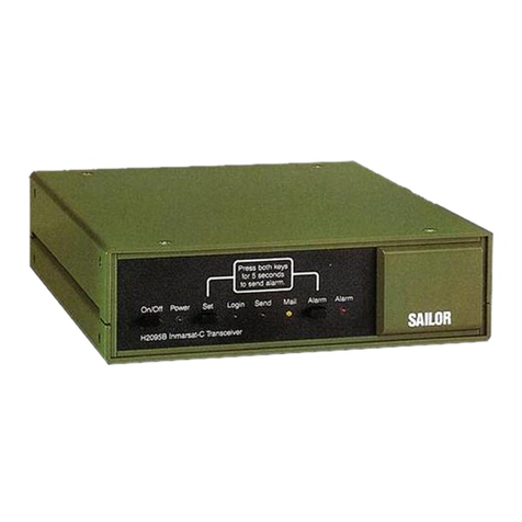
Thrane&Thrane TT-3020C Instruction sheet

VMS CapsatTransceiver
TT-3020C, TT-3022C, TT-3022D and
TT-3028CM
Configuration Manual


Thrane & Thrane
VMS CapsatTransceiver
TT-3020C, TT-3022C, TT-3022D and
TT-3028CM
Configuration Manual
CopyrightThrane & Thrane A/S
ALL RIGHTS RESERVED

Information in this document is subject to change without notice
and does not represent a commitment on the part of Thrane &
Thrane A/S.
© 2000 Thrane & Thrane A/S. All right reserved. Printed in Den-
mark.
Document Number TT98-112168-B.
Release Date: 9. November 2000


Table of Contents
9-Nov-00 Page i
Table of Contents
1Introduction......................................................................................................1-1
1.1 Anintroduction toterms......................................................................1-1
1.2 Short feature description ....................................................................1-3
1.2.1 Restriction to the SOLAS Fishery........................................1-5
2LES Interface ................................................................................................... 2.1
2.1 DNIDCommon Format....................................................................... 2.1
2.1.1 API Header Format.................................................................2.2
2.1.2 First part of Positioning Report............................................2.3
2.1.3 Second Part of Positioning Report......................................2.5
3Initialsetup oftransceiver.............................................................................3-1
3.1 TT-3020C SOLAS Transceiver ..........................................................3-1
3.1.1 Making a SOLAS Fishery Transceiver ................................3-1
3.1.2 Ocean Registration................................................................3-2
3.2 TT-3028CM Dual Mode Fishery Transceiver..................................3-3
3.2.1 Making a SOLAS Fishery Transceiver ................................3-3
3.2.2 Ocean Registration................................................................3-4
3.3 TT-3022D Fishery Transceiver..........................................................3-5
3.3.1 Ocean registration..................................................................3-5
3.4 TT-3022C Landmobile Transceiver.................................................3-6
3.4.1 Making a Landmobile vehicle surveillance
Transceiver..............................................................................................3-6
3.4.2 Ocean Registration................................................................3-7
4Transceiver Configuration.............................................................................4-1
4.1 Configuring the VMS behaviour.........................................................4-1
4.1.1 Quit............................................................................................4-2
4.1.2 Set all values to default.........................................................4-3
4.1.3 Date and time format.............................................................4-3
4.1.4 Antenna Blocked/Disconnected followed by normal
positionreport.........................................................................................4-6
4.1.5 Retransmit fail reports...........................................................4-6
4.1.6 Blocked GPS detection..........................................................4-7
4.1.7 Long to short report interval change...................................4-7

Table of Contents
Page ii 9-Nov-00
4.1.8 Nice power down support....................................................4-8
4.1.9 Disable Send LED on position report TX........................4-11
4.1.10 Stop button initiates position report..................................4-11
4.1.11 Disableposition reportinfos.............................................4-13
4.1.12 Password on da-command...............................................4-13
4.1.13 Only 1 packet per position report ......................................4-14
4.1.14 Mask out speed and course..............................................4-14
4.1.15 Disable GPS first fix beep...................................................4-15
4.1.16 'A' in provider downloads VMS DNID................................4-15
4.1.17 Use VMS DNID for special reports ...................................4-16
4.1.18 Hide remote connections...................................................4-17
4.1.19 Keep inactive connections.................................................4-18
4.1.20 MEMCode translation table...............................................4-18
4.1.21 Number of positions in storage queue............................4-19
4.1.22 Position report packet 2 -bit mask...................................4-20
4.1.23 Reporting intervals...............................................................4-21
4.1.24 Reporting interval change distance..................................4-22
4.1.25 VMS DNID and VMS LES ....................................................4-22
4.1.26 Number of active DNID in transceiver..............................4-23
4.2 Passwordprotection.........................................................................4-23
4.3 Automatic ocean region shift...........................................................4-26
4.4 Reduced transmission mode.........................................................4-27
4.5 Sleep mode ........................................................................................4-30
4.5.1 Setting up Sleep mode operation.....................................4-31
4.6 Surveillance zones ............................................................................4-33
4.6.1 Setting up surveillance zones............................................4-35
5Remote configuration of the transceiver via poll ......................................5-1
5.1VMSConfiguration...............................................................................5-1
5.2 Fishery Configuration (FI command) Poll.......................................5-5
5.3 Zone Configuration Poll......................................................................5-7
5.4 VMSSet-up Acknowledgement.........................................................5-9
5.5 FisherySet-up Poll Example...........................................................5-12
5.6 VMS connection for multiple ocean regions.................................5-14
5.7 Sleep mode Set-upPoll...................................................................5-17
5.8 Reduced transmission mode set-up poll.....................................5-18
6Developmenttips...........................................................................................6-1
7Index..................................................................................................................7-1
Table of Contents
9-Nov-00 Page iii


Table of Figures
9-Nov-00 Pagev
Table of Figures
Figure 1 System Overview..........................................................................................1-2
Figure 2 LES, DNID and member number.............................................................1-2
Figure 3 API header of DNID file...............................................................................2.2
Figure 4 First Part of Position Report.......................................................................2.3
Figure 5 Second Part of Position Report.................................................................2.5
Figure 6 TT-3020C Maritime Capsat Transceiver .................................................3-1
Figure 7 TT-3020C Maritime Capsat Transceiver .................................................3-3
Figure 8TT-3022D Fishery Capsat Transceiver.....................................................3-5
Figure 9 TT-3022C Land Mobile Transceiver.........................................................3-6
Figure 10 Fishery Configuration Menu (fi)...............................................................4-2
Figure 11 Position report format 1............................................................................4-4
Figure 12 Antenna blocked/Disconnected reports ................................................4-6
Figure 13 Automatic change of reporting interval ..................................................4-8
Figure 14 In-port button............................................................................................4-12
Figure 15 Reduced Transmission Mode .............................................................4-28
Figure 17 Position, speed and course shown graphically...............................4-29
Figure 18 Vessel/Vehicle track...............................................................................4-29
Figure 19 Reports from MES in reduced mode ..................................................4-29
Figure20 Radiusused tocheck for reduced transmission.............................4-30
Figure 21 Zone example..........................................................................................4-34
Figure 22 Poll Command Checksum Calculation ................................................5-4
Figure 23 Example of Remote Poll Configuration..............................................5-13
Figure 24 Open Connection Poll............................................................................5-15
Figure 25Sleep mode Set-upPoll .........................................................................5-17
Figure 26 Sleep mode Acknowledge Report.......................................................5-18
Figure 27 Reduced Mode Set-up Poll...................................................................5-18
Figure 28 Reduced Mode Acknowledge Report.................................................5-19

Table of Figures
Page vi 9-Nov-00
This page is intentionally left blank

Table of Tables
9-Nov-00 Page vii
Table of Tables
Table 1 Position report format 2................................................................................4-4
Table 2 Position report format 3................................................................................4-5
Table 3 Default Macro Encoded Messages.........................................................4-19
Table 4 Password Protected Commands...........................................................4-25
Table 5 Sleep Mode Command.............................................................................4-32
Table 6 Possible zone shapes..............................................................................4-34
Table 7 T&T Remote Configuration..........................................................................5-1
Table 8 T&T Poll Command List...............................................................................5-3
Table 9 Connection between entry number and parameters.............................5-7
Table 10 Connection between Zone type and Zone data ....................................5-8
Table11 Positive OpenConnection acknowledgement...................................5-16
Table 12 Negative Open Connection acknowledgement.................................5-16

Table of Tables
Page viii 9-Nov-00
This page is intentionally left blank

An introductiontoterms Introduction
9-Nov-00 Page 1-1
1Introduction
This manual provides instructions for configuring the Thrane &
Thrane fishery transceivers and land mobile transceiver for use in
Vessel/Vehicle Monitoring Systems. The manual provides informa-
tion for both the TT-3020C SOLAS GMDSS Transceiver, the TT-
3028CM Dual Mode SOLAS GMDSS Transceiver, the TT-3022D
Non-SOLAS Fishery Transceiver and for the TT-3022C Land Mobile
Transceiver.
The manual contains no information about general installation of
the equipment. This information should be found in the relevant in-
stallation manuals. The TT-3020C Installation Manual (document
number TT98-107880 ), the TT-3028CM Installation Manual
(document number TT98-111327), the TT-3022D Installation Man-
ual (document number TT98-107719) and the TT-3022C Installa-
tion Manual (document number TT98-107307).
This manual cover software versions from 3.28 and up.
1.1 An introduction to terms
This section describes the terms in vessel/vehiclesurveillance that
are needed to understand the role of Inmarsat and T&T in VMS.
The most important terms used in VMS are Land Earth Stations
(LES), VMS Data Network Id (DNID) and Member numbers.
Figure 1shows a typical transmission path of a position being
transferred from the Inmarsat-C transceiver in a fishery vessel to
the vessel surveillance centre. The same path applies-but in the
opposite direction -for commands send to the vessel.

Introduction Anintroduction to terms
Page 1-29-Nov-00
Land Earth StationFishing vessel Vesse surveillance
centre
Terrestrial
line
Figure 1System Overview
When a position is transmitted from the vessel/vehicle to the sur-
veillance centre the address of the recipient must be known by the
Inmarsat-C transceiver otherwise the transceiver will not know
where to send it. This address is called the VMS DNID and VMS
LES. Figure 2shows an antenna blocked position report being
sentto recipient LES 312 and DNID 12345.
Thrane&Thrane
Power Set Login Send Mail
TT-3022C
TT-3022D,TT-3020C,
TT-3028CM, TT-3022C
Antenna Blocked
55.44N12.28E
11:37 am
10 knot
120 degree
To:
VMS LES: 312
VMS DNID: 12345
From:
member 47
LES312
LES204
LES102
Figure 2LES, DNID and member number

Shortfeature description Introduction
9-Nov-00 Page 1-3
The member number has a similar meaning as the return address
on an envelope. The member number is used by the ves-
sel/vehicle surveillance centre to identify the transceiver that
transmitted the position report.
When a position report is received by the Land Earth Station (LES)
a DNID file is created from the packets received in the VMS DNID
mailbox. The DNID file can then be forwarded to the fishery authori-
ties or other vessel/vehicle surveillance authorities via the terres-
trial line. The type of network used to access the Inmarsat-C Land
Earth Station (X.25, PSTN etc.) is not discussed in this document. It
is also important to notice that the LES interface varies with the dif-
ferent producer of LES.
Position reports as transmitted by the Inmarsat-C transceiver are
one or two 15 bytes data packets on the satellite link but this i nfor-
mation is packed into a DNID format before it is transmitted to the
vessel/vehicle surveillance centre. Therefore it is the DNID format
that is being described throughout this manual.
1.2 Short feature description
The Thrane & Thrane Fishery Transceiver is the market leader in
Inmarsat-C Vessel Monitoring Systems. The Transceiver has been
approved as Fishery Monitoring Unit in a large number of countries
and offers a great variety of configurations depending on the spe-
cific needs.
In the following is a short list of the primary features in both of the
Thrane & Thrane Inmarsat-C fishery transceivers.
•Freely configurable position reporting interval
•Detection and reporting of Inmarsat-C antenna blockage
•Detection and reporting of GPS blockage

Introduction Shortfeature description
Page 1-49-Nov-00
•Configurable one or two packets report depending on the
need for speed and course information.
•4 different formats for date and timeinformation
•Remote configuration from VMS centre of key features in the
transceiver.
•Password protection of configuration and relevant commands.
•Possible reduced transmission mode with long and short re-
porting interval depending on vessel movements
•Button for initiating manual position report or indication in har-
bour status.
•Storing of up to 100 position reports when outside Inmarsat
coverage
•Configurable macro codes for different events.
•Possibility of retransmission of failed reports
•Possibility of hiding transmission (Not applicable for SOLAS
transceiver)
•Sleep mode where the transceiver automatic turns off to save
power when not sending (Not applicable for SOLAS trans-
ceiver)
•Differentiation between “Power down” status and “Nice power
down” status (special power off button).
•Surveillance zones giving a geographical area and a reporting
interval to be usedin that area.
The Thrane & Thrane Land Mobile Transceiver includes full VMS
functionality identical to its maritime counterpart in both behaviour
and in packet format.

Shortfeature description Introduction
9-Nov-00 Page 1-5
1.2.1 Restriction to the SOLAS Fishery
Some of the features described in this manual are in conflict with
the SOLAS GMDSS requirements. Therefore these features arenot
implemented in the TT-3020C SOLAS Fishery Transceiver or in the
TT-3028CM Dual Mode SOLAS GMDSS Transceiver.
A short list of the missing features are listed in the following. A
more comprehensive description of the feature is given in the rele-
vant sections of this manual.
•Nice Power Down Support. Please see section4.1.8.
•Disable Send LED on position report TX. Please see section
4.1.9
•Position report packet 2 -bit mask. Due to the fact that no
GMDSS Message Terminal supports this feature. Please see
section 4.1.22.
•Sleep mode. Please see section4.5.
•Password protection of the commands “Login” and “Scan”.
Please see section 4.2.

Introduction Shortfeature description
Page 1-69-Nov-00
This page is intentionally left blank
Other manuals for TT-3020C
2
This manual suits for next models
3
Table of contents
Other Thrane&Thrane Transceiver manuals

Thrane&Thrane
Thrane&Thrane TT-3020B User manual

Thrane&Thrane
Thrane&Thrane tt-3022d User manual

Thrane&Thrane
Thrane&Thrane TT-3020B Product manual

Thrane&Thrane
Thrane&Thrane TT-3020C User manual

Thrane&Thrane
Thrane&Thrane SAILOR 6249 User manual

Thrane&Thrane
Thrane&Thrane Sailor RT5022 User manual

Thrane&Thrane
Thrane&Thrane Explorer 527 User manual

Thrane&Thrane
Thrane&Thrane SP3300 VHF Operating instructions

Thrane&Thrane
Thrane&Thrane TT-3020C User manual

Thrane&Thrane
Thrane&Thrane TT-3026L easyTrack User manual