manuals.online logo
Brands
  1. Home
  2. •
  3. Brands
  4. •
  5. THT-EX
  6. •
  7. Lighting Equipment
  8. •
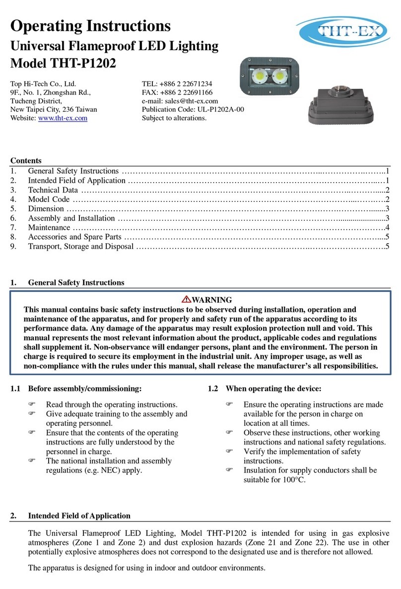
  9. THT-EX HazLoc P1202 Manual

THT-EX HazLoc P1202 Manual

HazLoc LED LUMINAIRE
Installation and Maintenance Manual
HazLoc P1202
Top Hi-Tech Co., Ltd.
5F., No. 113, Zhongcheng Rd.,
Tucheng District,
New Taipei City, 236 Taiwan
Website: www.tht-ex.com
TEL: +886 2 22689570
FAX: +886 2 22689571
e-mail: sales@tht-ex.com
Pub. Code: 201412ELP1202ZUS01
Subject to alterations
1. General Information
HazLoc P1202 LED Luminaires are suitable for use in
the following hazardous (classified) areas as defined
by the National Electrical Code (NEC) and Canadian
Electrical Code (CEC):
lClass I, Division 2, GroupsA, B, C, D
lWet Locations (UL 1598)
Refer to the luminaire nameplate for specific
classification information, maximum ambient
temperature suitability and corresponding operating
temperature (T-Code).
HazLoc P1202 LED Luminaire is designed for using in
indoors and outdoors environment.
Rated Voltage: 277/480/120 Vac, 50 & 60 Hz
Ambient Temperate Range: -40°C ~ +40°C
____________________________________________________________________________________________
WARNING
uTo avoid the risk of fire, explosion or electric shock, this product should be installed, inspected and
maintained by a qualified electrician only, in accordance with all applicable codes and regulations.
uTo avoid electric shock:
üBe certain electrical power is OFF before and during installation and maintenance.
üLuminaire must be supplied by a wiring system with an equipment grounding conductor.
u
To avoid
explosion:
üMake sure that the supply voltage is the same as the luminaire voltage.
üDo not install where the marked operating temperatures exceed the ignition temperature of the
hazardous atmosphere.
üDo not operate in ambient temperatures above those indicated on the luminaire nameplate.
üAll gasket seals must be clean and undamaged.
üUse proper supply wiring as specified on the luminaire nameplate.
üBefore dismounting, electrical power to the luminaire must be turned off. Keep tightly closed
when in operation.
uTo avoid burning hands, ensure the luminaire is cool when performing maintenance.
____________________________________________________________________________________________
2. Dimensions (All Dimensions in mm) – Subject to Alterations
3. Model Code
THT
H
1202
Z
C
B
C
9
D0
C90
Mounting bracket type, C90 = Ceiling mounting 90°*
Wattage, D0 = 40 W
Voltage, 9 = 277 Vac, C = 480 Vac, 6 = 120 Vac
CCT, C = cool white; W = warm white
LED module type, B = DCOB (driver chip on board)
Type of top Cover, C = Top cover with M20 or NPT 3/4”
opening; D = Top cover without opening.
Internal control code
Type of product, H – Lighting for using in Class I, Div. 2
Brand, THT=Top Hi-Tech Co., Ltd.
* C90 = Ceiling mounting 90°, W25 = Wall mounting 25°, W90 = Wall mounting 90°, H25 = Pendant mounting 25°, H90 =
Pendant mounting 90°
4. Technical Data
Item Description
Rated Voltage
277
/480/120
Vac, 50 & 60
Hz
(
Note information on type label
)
Power Factor
cos φ≧0.9
Ambient Temperate Range
-
40°
C ~ +40
°
C
Material
Enclosure
Glass Aluminum alloy
Temperature-resistant pressed glass
LED Service Life
60,000 hrs
Entrance
Hole
N
PT 3/4”
or M20
threaded hole
Mounting Type / Weight
Ceiling
M
ounting
Wall
M
ounting
Pendant
M
ounting
3
.4
kg
3.
6
kg
3
.
6
kg
5. Assembly and Installation
5.1 Electrical Connection
5.1.1 Cable Entries through Top Cover
FLoosen the M4 set screw of Top Cover of the
luminaire. (Figure 1)
FLoosen the Top Cover of the luminaire and
remove it.
FThe thread of cable entry hole of Top Cover is
NPT 3/4” or M20.
FAttach the Top Cover to suitable conduit.
FInsert the cable from outside through the conduit
and the cable entry hole of Top Cover.
FIntroduce the wires of the luminaire with wires of
cable by attached closed-end-terminals as
following (Figure 2):
Black-wire connects to Neutral;
Red-wire connects to Live;
Green-wire connects to Ground.
FThread the Top Cover and torque until
wrench-tight.
FTighten the M4 set screw of Top Cover with
torque value 1 N-m.
FCheck the tightness of conduit and Top Cover.
5.1.2 Cable Entries through Entry Hole of Tank
FLoosen the Plug from the Tank and remove it.
(Figure 3)
FThe thread of cable entry hole of Tank is M20.
FAttach the Tank to suitable conduit.
FInsert the cable from outside through the conduit
and the cable entry hole of Tank.
FIntroduce the wires of the luminaire with wires of
cable by attached closed-end-terminals as
following (Figure 2):
Black-wire connects to Neutral;
Red-wire connects to Live;
Green-wire connects to Ground.
FThread the conduit and torque until wrench-tight
with torque value 40 N-m.
FCheck the tightness of conduit.
5.2 Mounting Bracket Installation
5.2.1 Wall Mounting & Pendant Mounting Bracket
FThe mounting bracket is both for the use of wall
mounting and Pendant mounting.
FPosition the bracket holders and fix it by means
of the provided M6 screws, 24.5 kgf-cm. (Figure
4)
FSecure the wall/pendant mounting bracket to the
structure by using six fasteners (not provided).
(Figure 5)
FThe lighting can be adjusted up and down by 25°.
(See picture in Technical Data)
5.2.2 Ceiling Mounting Bracket (C90)
FThe mounting bracket is for the use of ceiling
mounting.
FPosition the bracket holders and fix it by means
of the provided M6 screws, 24.5 kgf-cm. (Figure
6)
FSecure the wall mounting bracket to the structure
by using four fasteners (not provided). (Figure 7) Figure 7
Figure 6
Figure 4
Red: Live wire
Green: Ground wire
Black: Neutral wire
Figure 1 Figure 2
Figure 3
Figure 5
5.3 Putting into Service
Before putting into operating, it’s necessary to ensure that:
Fthe lighting is correctly installed.
Fthe connection has been correctly made.
Fthe cable has been inserted correctly.
6. Maintenance
uTo avoid personal injury, disconnect power to the light and allow the unit to cool down before performing
maintenance.
uPerform visual, electrical, and mechanical inspections on a regular basis. The environment and frequency of
use should determine this. However, it is recommended that checks be made at least once a year. Frequency of
use and environment should determine this. It is recommended to follow an Electrical Preventive
Maintenance Program as described in the National Fire ProtectionAssociation Bulletin NFPANo. 70B:
Recommended Practice for Electrical Equipment Maintenance.
uThe lens should be cleaned periodically to ensure continued lighting performance. Clean the lens with a clean,
damp, non-abrasive, lint-free cloth. If this is not sufficient, use a mild soap or a liquid cleaner. Do not use an
abrasive, strong alkaline or acid cleaneras damage may occur.
uInspect the cooling fins on the luminaire to ensure that they are free of any contamination (i.e. excessive dust
build-up). Clean with a non-abrasive cloth if needed.
uElectrically check to make sure that all connections are clean and tight.
uMechanically check that all parts are properly assembled.
7. Transport, Storage and Disposal
uTransport and storage is only allowed in the original packaging, on the way pointed out on the carton box.
uTransport – Shock-free in its original carton, do not drop, and handle carefully.
uStore – Store in a dry place in its original packaging.
uDisposal – Ensure environmentally friendly disposal of all components according to the legal regulations.

Other THT-EX Lighting Equipment manuals

THT-EX L1512D Manual

THT-EX

THT-EX L1512D Manual

THT-EX L1512 User manual

THT-EX

THT-EX L1512 User manual

THT-EX L1601C User manual

THT-EX

THT-EX L1601C User manual

THT-EX THT-L1219 User manual

THT-EX

THT-EX THT-L1219 User manual

THT-EX L1319 User manual

THT-EX

THT-EX L1319 User manual

THT-EX THT-P1202 User manual

THT-EX

THT-EX THT-P1202 User manual

Popular Lighting Equipment manuals by other brands

Lightmybricks LEGO VENETIAN HOUSES 910023 installation guide

Lightmybricks

Lightmybricks LEGO VENETIAN HOUSES 910023 installation guide

Quoizel ASH33556B0 installation guide

Quoizel

Quoizel ASH33556B0 installation guide

ProLights BB5PIX user manual

ProLights

ProLights BB5PIX user manual

Show Tec Club Barrel manual

Show Tec

Show Tec Club Barrel manual

Integratech PHB75 manual

Integratech

Integratech PHB75 manual

Expolite TourLED 42 CM IP33 user manual

Expolite

Expolite TourLED 42 CM IP33 user manual

IKEA PS 2014 instruction manual

IKEA

IKEA PS 2014 instruction manual

EuroLite E-14 Lampholder user manual

EuroLite

EuroLite E-14 Lampholder user manual

Hosen HS--MB200 user manual

Hosen

Hosen HS--MB200 user manual

Chauvet Intimidator COLOR LED Features & specification

Chauvet

Chauvet Intimidator COLOR LED Features & specification

Rollei Candela 330 Bi-Color manual

Rollei

Rollei Candela 330 Bi-Color manual

Aervoe Classic Road Flare operating instructions

Aervoe

Aervoe Classic Road Flare operating instructions

Hayward OmniHub installation manual

Hayward

Hayward OmniHub installation manual

Quoizel RAM8405MBK installation guide

Quoizel

Quoizel RAM8405MBK installation guide

Philips 56494-31-16 user manual

Philips

Philips 56494-31-16 user manual

ACME LED-212RGB user manual

ACME

ACME LED-212RGB user manual

Nicols PAR LED 1812 X II user manual

Nicols

Nicols PAR LED 1812 X II user manual

Lightolier Calculite ProSpec PB1H3870 specification

Lightolier

Lightolier Calculite ProSpec PB1H3870 specification

manuals.online logo
manuals.online logoBrands
  • About & Mission
  • Contact us
  • Privacy Policy
  • Terms and Conditions

Copyright 2025 Manuals.Online. All Rights Reserved.