THT-EX THT-P1202 User manual

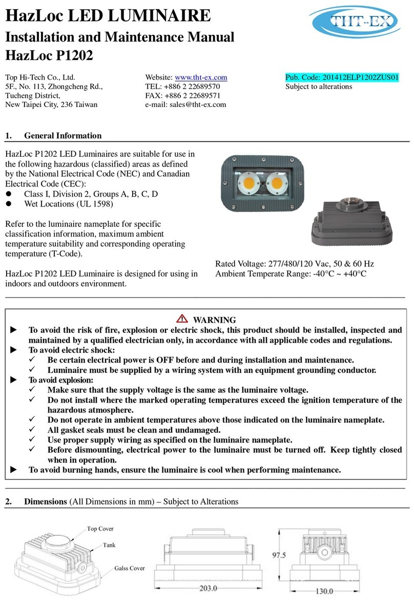
Operating Instructions
Universal Flameproof LED Lighting
Model THT-P1202
Top Hi-Tech Co., Ltd.
9F., No. 1, Zhongshan Rd.,
Tucheng District,
New Taipei City, 236 Taiwan
Website: www.tht-ex.com
TEL: +886 2 22671234
FAX: +886 2 22691166
e-mail: sales@tht-ex.com
Publication Code: UL-P1202A-00
Subject to alterations.
Contents
1. General Safety Instructions ………………………………………………………………..…………….……..1
2. Intended Field of Application ………………………………………………………………………………..…1
3. Technical Data ……………………………………………………………….……….……………..……….....2
4. Model Code …………………………………………………………………………………………...…….….2
5. Dimension ……………………………………………………………………………………….………….......3
6. Assembly and Installation ……………………………………………………………………….......................3
7. Maintenance …………………………………………………………………………………………………….4
8. Accessories and Spare Parts …………………………………………………………………………………....5
9. Transport, Storage and Disposal ……………………………………………………….……………………….5
1. General Safety Instructions
WARNING
This manual contains basic safety instructions to be observed during installation, operation and
maintenance of the apparatus, and for properly and safety run of the apparatus according to its
performance data. Any damage of the apparatus may result explosion protection null and void. This
manual represents the most relevant information about the product, applicable codes and regulations
shall supplement it. Non-observance will endanger persons, plant and the environment. The person in
charge is required to secure its employment in the industrial unit. Any improper usage, as well as
non-compliance with the rules under this manual, shall release the manufacturer’s all responsibilities.
1.1 Before assembly/commissioning:
FRead through the operating instructions.
FGive adequate training to the assembly and
operating personnel.
FEnsure that the contents of the operating
instructions are fully understood by the
personnel in charge.
FThe national installation and assembly
regulations (e.g. NEC) apply.
1.2 When operating the device:
FEnsure the operating instructions are made
available for the person in charge on
location at all times.
FObserve these instructions, other working
instructions and national safety regulations.
FVerify the implementation of safety
instructions.
FInsulation for supply conductors shall be
suitable for 100°C.
2. Intended Field ofApplication
The Universal Flameproof LED Lighting, Model THT-P1202 is intended for using in gas explosive
atmospheres (Zone 1 and Zone 2) and dust explosion hazards (Zone 21 and Zone 22). The use in other
potentially explosive atmospheres does not correspond to the designated use and is therefore not allowed.
The apparatus is designed for using in indoor and outdoor environments.

3. Technical Data
Item Description
Explosion Protection
USA(UL)
Gas Explosion Protection
Dust Explosion Protection
Canada (cUL)
Gas Explosion Protection
Class I, Zone 1, AEx d IIB+H2T5 Gb
Zone 21, AEx tb IIIC T100°C Db
Ex d IIB+H
2
T5 Gb X
Rated Voltage
USA/Canada
120 Vac / 277 Vac (±10%), 50 & 60 Hz
Note information on type label.
Power Factor
cos φ≧0.9
Ambient Temperate Range
F
or
USA/Canada (UL):
-
4
0°
C ~ +40
°
C
Degree of Protection
IP6
7
Material
Enclosure
Glass Aluminum alloy
Tempered glass
LED Service Life
6
0,000 h
rs
Entrance Hole
NPT 3/4
”
or M20
threaded hole
Weight
Ceiling
mounting
Bracket
Pendant
Mounting Bracket
Wall Mounting Bracket
3.4
kg
3.6
kg
3.6kg
4. Model Code
THT
E
1202
Z
C
B
C
6
D
4
C90
Mounting bracket type, C90 = Ceiling mounting 90°*
Wattage, D4 = 44 W; D0 = 40W
Voltage, 6 = 120 Vac; 9 = 277 Vac
CCT, C = cool white; W = warm white
LED module type, B = DCOB (driver chip on board)
Type of top Cover, C = Top cover with M20 or NPT 3/4”
opening; D = Top cover without opening
Internal control code, maybe any one alphabet fromAto Z
Model name
Type of product, E = Flame Proof Lighting
Brand, THT=Top Hi-Tech Co., Ltd.
* C90 = Ceiling mounting 90°, W25 = Wall mounting 25°, W90 = Wall mounting 90°, H25 = Pendant mounting 25°, H90 =
Pendant mounting 90°

5. Dimensions (All Dimensions in mm) – Subject to Alterations
6. Assembly and Installation
6.1 Electrical Connection
6.1.1 Cable Entries through Top Cover
FLoosen the M4 set screw of Top Cover of the
luminaire. (Figure 1)
FLoosen the Top Cover of the luminaire and
remove it.
FThe thread of cable entry hole of Top Cover is
NPT 3/4” or M20.
FAttach the Top Cover to suitable conduit.
FInsert the cable from outside through the conduit
and the cable entry hole of Top Cover.
FIntroduce the wires of the luminaire with wires of
cable by attached closed-end-terminals as
following (Figure 2):
Black-wire connects to Neutral;
Red-wire connects to Live;
Green-wire connects to Ground.
FThread the Top Cover and torque until
wrench-tight.
FTighten the M4 set screw of Top Cover with
torque value 1 N-m.
FCheck the tightness of conduit and Top Cover.
6.1.2 Cable Entries through Entry Hole of Tank
FLoosen the Plug from the Tank and remove it.
(Figure 3)
FThe thread of cable entry hole of Tank is M20.
FAttach the Tank to suitable conduit.
FInsert the cable from outside through the conduit
and the cable entry hole of Tank.
FIntroduce the wires of the luminaire with wires of
cable by attached closed-end-terminals as
following (Figure 2):
Black-wire connects to Neutral;
Red-wire connects to Live;
Green-wire connects to Ground.
FThread the conduit and torque until wrench-tight
with torque value 40 N-m.
FCheck the tightness of conduit.
6.2 Mounting Bracket Installation
6.2.1 Wall Mounting & Pendant Mounting Bracket (W25, W90 & H25, H90)
FThe mounting bracket is both for the use of wall
mounting and Pendant mounting.
FPosition the bracket holders and fix it by means of
the provided M6 screws, 24.5 kgf-cm. (Figure 4)
FSecure the wall/pendant mounting bracket to the
structure by using six fasteners (not provided).
(Figure 5)
FThe lighting can be adjusted up and down by 25°.
Red: Live wire
Green: Ground wire
Black: Neutral wire
Figure 1 Figure 2
Figure 3
Figure 4 Figure 5

6.2.2 Ceiling Mounting Bracket (C90)
FThe mounting bracket is for the use of ceiling
mounting.
FPosition the bracket holders and fix it by means of
the provided M6 screws, 24.5 kgf-cm. (Figure 6)
FSecure the wall mounting bracket to the structure
by using four fasteners (not provided). (Figure 7)
6.3 Putting into Service
Before putting into operating, it’s necessary to ensure that:
Fthe lighting is correctly installed.
Fthe connection has been correctly made.
Fthe cable has been inserted correctly.
Finsulation for supply conductors shall be suitable for 100°C.
7. Maintenance
7.1 Regular Maintenance
FConsult the relevant national regulations (e.g.
NEC) to determine the type and extent of
inspections.
FArrange the plan of regular inspection with the
equipment so that any defects in the equipment
which may be anticipated are promptly detected.
To check as part of the maintenance schedule as
following:
FCracks or damages on the glass cover and/or on
the enclosure.
FCondition of the connecting cables.
FScrews of the mounting bracket are tightened.
WARNING
uTo reduce the risk of ignition due to electrostatic discharge, avoid contact with the luminaire while
an explosive atmosphere is present. Clean only with a damp cloth.
uContact manufacturer for information on the flameproof joints.
uInstructions for safety (i.e. putting into service, use, assembling, maintenance, installation,
adjustment, and mounting).
uTools used for the equipment.
uInstructions relevant to the safe installation, use, and operation of the equipment shall be in both
English and French (for Canada).
uTo avoid personal injury, disconnect power to the light and allow the unit to cool down before
performing maintenance.
uPerform visual, electrical, and mechanical inspections on a regular basis. The environment and
frequency of use should determine this. However, it is recommended that checks be made at least
once a year. Frequency of use and environment should determine this. It is recommended to follow
an Electrical Preventive Maintenance Program as described in the National Fire Protection
Association Bulletin NFPA No. 70B: Recommended Practice for Electrical Equipment Maintenance.
uThe lens should be cleaned periodically to ensure continued lighting performance. Clean the lens
with a clean, damp, non-abrasive, lint-free cloth. If this is not sufficient, use a mild soap or a liquid
cleaner. Do not use an abrasive, strong alkaline or acid cleaner as damage may occur.
uInspect the cooling fins on the luminaire to ensure that they are free of any contamination (i.e.
excessive dust build-up). Clean with a non-abrasive cloth if needed.
uElectrically check to make sure that all connections are clean and tight.
uMechanically check that all parts are properly assembled.
uMaintenance work is not permitted on flameproof enclosures. Repairs are only to be carried out by
the manufacturer. Unauthorized repair shall cause the manufacturer’s liability and warranty
expires.
Figure 7
Figure 6

7.2 Cleaning
Flameproof gap:
FClean the flameproof gap regularly with an acid-free grease which is compatible with aluminum.
FCorrosion prevention by means of a coat of paint is forbidden.
8. Accessories and Spare Parts
9. Transport, Storage and Disposal
FTransport and storage is only allowed in the original packaging, on the way pointed out on the carton box.
FTransport – Shock-free in its original carton, do not drop, and handle carefully.
FStore – Store in a dry place in its original packaging.
FDisposal – Ensure environmentally friendly disposal of all components according to the legal regulations.
WARNING
Do not clean the corroded gap using abrasives or a steel brush. Use chemical agents for cleaning, such as
reducing oils.
WARNING
Use only original THT-EX accessories and spare parts. For accessories and spare parts, see data sheet at
www.tht-ex.com.
Table of contents
Other THT-EX Lighting Equipment manuals
Popular Lighting Equipment manuals by other brands
PLG
PLG ICON 2 user manual

Acolyte
Acolyte NEONLYTE installation manual

Lena Lighting
Lena Lighting IQ SUN MED Installation instruction
Armacost Lighting
Armacost Lighting RibbonFlex Home 421502 quick start guide

IKEA
IKEA RYET quick start guide
HUBBELL LIGHTING
HUBBELL LIGHTING Dual-Lite EVE Series Installation, operation and maintenance instructions
Robin
Robin Robin MMX Spot user manual
Vision & Control
Vision & Control LDLF60x180-IR850/UDC Instructions for use
Deco Lighting
Deco Lighting DWH-LED installation instructions
Eagletone
Eagletone Crystal Bowl user guide

CREE LIGHTING
CREE LIGHTING Noctura Series installation instructions
COEF
COEF EMULATION WRGB Operation manual
