Thytronic NG10 User manual

NG10 - Manual - 04 - 2022
MANUAL
NG10
BIASED DIFFERENTIAL FOR
GENERATORS/MOTORS/SHORT LINES

TABLE OF CONTENTS 2
NG10 - Manual - 04 - 2022
TABLE OF CONTENTSTABLE OF CONTENTS
1 INTRODUCTION 5
Scope and liability...........................................................................................................................................................................................5
Applicability......................................................................................................................................................................................................5
Conformity ........................................................................................................................................................................................................5
Technical support............................................................................................................................................................................................5
Copyright...........................................................................................................................................................................................................5
Warranty...........................................................................................................................................................................................................5
Safety recommendations...............................................................................................................................................................................5
Insulation tests ................................................................................................................................................................................................5
Product identification .....................................................................................................................................................................................6
Environment .....................................................................................................................................................................................................6
Graphical conventions ...................................................................................................................................................................................6
Glossary/definitions ........................................................................................................................................................................................6
2 GENERAL 10
Preface........................................................................................................................................................................................................... 10
Photo .............................................................................................................................................................................................................. 10
Main features.................................................................................................................................................................................................11
3 TECHNICAL DATA 12
3.1 GENERAL............................................................................................................................................................................................................12
Product standard for measuring relays.....................................................................................................................................................12
Mechanical data ...........................................................................................................................................................................................12
Insulation ........................................................................................................................................................................................................12
Voltage dip and interruption........................................................................................................................................................................12
EMC tests for interference immunity.........................................................................................................................................................12
Emission......................................................................................................................................................................................................... 13
Mechanical tests.......................................................................................................................................................................................... 13
Climatic tests................................................................................................................................................................................................. 13
Safety ............................................................................................................................................................................................................. 13
Certifications................................................................................................................................................................................................. 13
3.2 INPUT CIRCUITS ...............................................................................................................................................................................................14
Auxiliary power supply Uaux ......................................................................................................................................................................14
Phase current input circuits (side H and side L)......................................................................................................................................14
Residual current input circuit......................................................................................................................................................................14
Binary input circuits......................................................................................................................................................................................14
Block input (Logic selectivity) .....................................................................................................................................................................14
3.3 OUTPUT CIRCUITS............................................................................................................................................................................................14
Relays..............................................................................................................................................................................................................14
Block output (Logic selectivity)...................................................................................................................................................................15
3.4 MMI.....................................................................................................................................................................................................................15
3.5 COMMUNICATION INTERFACES ...................................................................................................................................................................15
Local port........................................................................................................................................................................................................15
Remote ports..................................................................................................................................................................................................15
3.6 GENERAL SETTINGS ........................................................................................................................................................................................16
Rated values (Base)......................................................................................................................................................................................16
Input sequence .............................................................................................................................................................................................16
Polarity [3]............................................................................................................................................................................................................................................................................16
3.7 PROTECTIVE FUNCTIONS ...............................................................................................................................................................................17
Thermal protection with Pt100 probes - 26 ...............................................................................................................................................17
Residual overcurrent or high impedance differential restricted ground fault - 50N/51N - 87NHIZ ................................................17
Low impedance restricted ground fault - 64REF side H......................................................................................................................... 18
Breaker failure - BF...................................................................................................................................................................................... 18
3.8 CONTROL AND MONITORING....................................................................................................................................................................... 19
Trip Circuit Supervision side H and side L - 74TCS................................................................................................................................. 19
Selective block - BLOCK2 ........................................................................................................................................................................... 19
Circuit Breaker supervision........................................................................................................................................................................ 19
CT supervision - 74CT side H...................................................................................................................................................................... 19
CT supervision - 74CT side L....................................................................................................................................................................... 19
Pilot wire diagnostic .................................................................................................................................................................................... 19
Demand measures....................................................................................................................................................................................... 19
Oscillography (DFR) ..................................................................................................................................................................................... 20
PLC (Programmable Logic Controller) ...................................................................................................................................................... 20
3.9 METERING..........................................................................................................................................................................................................21

TABLE OF CONTENTS 3
NG10 - Manual - 04 - 2022
Accuracy (type tests)....................................................................................................................................................................................21
Measures........................................................................................................................................................................................................21
4 FUNCTION CHARACTERISTICS 22
4.1 HARDWARE DESCRIPTION.............................................................................................................................................................................22
Power supply board..................................................................................................................................................................................... 23
CPU board...................................................................................................................................................................................................... 23
Input board .................................................................................................................................................................................................... 23
MMI (keyboard, LED and display) ............................................................................................................................................................. 23
4.2 SOFTWARE DESCRIPTION ..............................................................................................................................................................................24
Base software................................................................................................................................................................................................24
Real-time operating system.........................................................................................................................................................................24
Task..................................................................................................................................................................................................................24
Drivers.............................................................................................................................................................................................................25
Application Software....................................................................................................................................................................................25
Data Base.......................................................................................................................................................................................................25
Self test (Application) ...................................................................................................................................................................................25
Development tools (Builder)........................................................................................................................................................................25
4.3 I/O DESCRIPTION..............................................................................................................................................................................................26
Metering inputs .............................................................................................................................................................................................26
Signal processing..........................................................................................................................................................................................26
Conventions................................................................................................................................................................................................... 29
Polarity reversal ........................................................................................................................................................................................... 30
Use of measured values...............................................................................................................................................................................31
Binary inputs ..................................................................................................................................................................................................32
Output relays..................................................................................................................................................................................................37
LED indicators............................................................................................................................................................................................... 39
Communication interfaces...........................................................................................................................................................................41
4.4 PROTECTIVE ELEMENTS .................................................................................................................................................................................42
Rated values...................................................................................................................................................................................................42
Thermal protection with RTD thermometric probes - 26 ........................................................................................................................44
Residual overcurrent / High impedance restricted ground fault - 50N/51N-87NHIZ.........................................................................46
Low impedance restricted ground fault- 64REF.......................................................................................................................................56
Differential protection for generator-motor-short line (87G-M-L) ....................................................................................................... 60
Breaker failure - BF...................................................................................................................................................................................... 70
4.5 CONTROL AND MONITORING........................................................................................................................................................................72
Logical block - BLOCK1................................................................................................................................................................................72
Selective block -BLOCK2 .............................................................................................................................................................................74
Logic block summary................................................................................................................................................................................... 79
Remote tripping ............................................................................................................................................................................................ 80
Frequency tracking.......................................................................................................................................................................................81
CT supervision - 74CT - side H and side L.................................................................................................................................................82
Trip circuit supervision - 74TCS ................................................................................................................................................................. 83
Circuit breaker supervision .........................................................................................................................................................................86
Demand measures....................................................................................................................................................................................... 89
Oscillography ............................................................................................................................................................................................... 89
5 MEASURES, LOGIC STATES AND COUNTERS 90
Measures....................................................................................................................................................................................................... 90
Protection ...................................................................................................................................................................................................... 90
Delayed inputs.............................................................................................................................................................................................. 90
Internal states............................................................................................................................................................................................... 90
Relays..............................................................................................................................................................................................................91
Counters..........................................................................................................................................................................................................91
Self test ...........................................................................................................................................................................................................91
Pilot wire diagnostic .....................................................................................................................................................................................92
Selective Block - BLOCK2............................................................................................................................................................................92
Fault recording - SFR....................................................................................................................................................................................92
Event recording - SER...................................................................................................................................................................................92
Oscillography - DFR ..................................................................................................................................................................................... 93
6 INSTALLATION 95
6.1 PACKAGING.......................................................................................................................................................................................................95
6.2 MOUNTING........................................................................................................................................................................................................95
6.3 ELECTRICAL CONNECTIONS ......................................................................................................................................................................... 99
6.4 NOMINAL CURRENT InAND IEn SETTING ................................................................................................................................................107
6.5 LED ALLOCATION............................................................................................................................................................................................111
6.6 FINAL OPERATIONS .......................................................................................................................................................................................111

TABLE OF CONTENTS 4
NG10 - Manual - 04 - 2022
7 PROGRAMMING AND SETTINGS 112
7.1 SW ThyVisor ....................................................................................................................................................................................................112
ThyVisor installation....................................................................................................................................................................................112
ThyVisor use.................................................................................................................................................................................................112
7.2 MMI (Man Machine Interface) ................................................................................................................................................................... 113
Reading variables (READ)......................................................................................................................................................................... 113
Setting modifying (SET) ............................................................................................................................................................................. 113
TEST...............................................................................................................................................................................................................115
COMMUNICATION......................................................................................................................................................................................115
Circuit breaker commands ........................................................................................................................................................................116
Enable / block changes via keyboard - Password.................................................................................................................................116
7.3 MODULES MANAGEMENT ...........................................................................................................................................................................117
7.4 MAINTENANCE.............................................................................................................................................................................................. 118
7.5 REPAIR............................................................................................................................................................................................................. 118
7.6 PACKAGING.................................................................................................................................................................................................... 118
8 APPENDIX 119
8.1 APPENDIX A1 - Inverse time IEC curves .................................................................................................................................................. 119
Mathematical formula............................................................................................................................................................................... 119
Measures residual overcurrent 50N/51N - Standard inverse time curve (IEC 60255-3/BS142 type A) ....................................... 120
Measures residual overcurrent 50N/51N - Very inverse time curve (IEC 60255-3/BS142 type B).................................................121
Measures residual overcurrent 50N/51N - Extremely inverse time curve (IEC 60255-3/BS142 type C) .......................................122
8.2 APPENDIX A2 - Inverse time ANSI/IEEE curves ...................................................................................................................................... 123
Mathematical formula............................................................................................................................................................................... 123
Measured residual overcurrent 50N/51N - Moderately inverse time curve (ANSI/IEEE type MI)...............................................124
Measured residual overcurrent 50N/51N - Very inverse time curve (ANSI/IEEE type VI) ............................................................125
Measured residual overcurrent 50N/51N - Extremely inverse time curve (ANSI/IEEE type EI) ...................................................126
8.3 APPENDIX A3 - Inverse time EM curves ...................................................................................................................................................127
Mathematical formula................................................................................................................................................................................127
Measured residual overcurrent 50N/51N - Electromechanical inverse curves (EM)................................................................... 128
8.4 APPENDIX B1 - I/O Diagram ........................................................................................................................................................................ 129
8.5 APPENDIX B2 - Interfaces ........................................................................................................................................................................... 130
8.6 APPENDIX B3- Connection diagrams .........................................................................................................................................................131
8.7 APPENDIX C - Dimensions............................................................................................................................................................................134
8.8 APPENDIX D - Setting table..........................................................................................................................................................................135
8.9 APPENDIX E - EC Declaration of conformity............................................................................................................................................. 158

5
5NG10 - Manual - 01 - 2015 INTRODUCTION
1 INTRODUCTION1 INTRODUCTION
Scope and liability
This document describes the functions, the technical data of NG10 devices; instructions for mount-
ing, setting and commissioning are included.
This manual has been checked out, however, deviations from the description cannot be completely
ruled out, so that no liability in a legal sense for correctness and completeness of the information or
from any damage that might result from its use is formally disclaimed.
The information given in this document is reviewed regularly; any corrections and integration will be
included in subsequent editions that are identified by the date of revision.
We appreciate any suggestions for improvement.
We reserve the right to make technical improvements without notice.
Applicability
This manual is valid for NG10 devices with firmware version 2.00 and following.
Conformity
The product complies with the CE directives:
• EMC Council Directives: 2014/30/EC
• Low voltage Directives: 2014/35/EC
Technical support
Contact: Service tecnico THYTRONIC www.thytronic.it
Copyright
All right reserved; It is forbidden to copy, modify or store material (document and sw) protected by
copyright without Thytronic consent.
Warranty
Thytronic warrants devices against defects in materials and workmanship under normal use for a
period of ONE (1) YEAR from the date of retail purchase by the original end-user purchaser (“War-
ranty Period”).
Safety recommendations
The warming contained in this document are all-important for safety; special attention must be paid
to the following symbols:
Installation and commissioning must be carried out by qualified person; Thytronic assumes no re-
sponsibility for damages caused from improper use that does not comply all warning and caution in
this manual.
In particular the following requirements must be met:
• Remove power before opening it.
• Verify the voltage absence by means suitable instrumentation on relay connections; attention must
be paid to all circuits supplied by external sources (binary input, CT, etc...)
• Care must be taken when handling metal parts.
Insulation tests
After insulation tests, hazardous voltages (capacitor charges,...) may be arise; it is advisable to grad-
ually reduce the test voltage avoiding to erase it abruptly.
DANGER Death, severe personal injury or substantial property damage will result if proper precautions
are not taken
WARNING Death, severe personal injury or substantial property damage can result if proper precautions
are not taken.
CAUTION
Settings must be established on the basis of a coordination study.
Numerical values inside examples have educational purpose only; they don’t be used, in no way,
for actual applications.
CAUTION Minor personal injury or property damage can result if proper precautions are not taken

6
6NG10 - Manual - 01 - 2015 INTRODUCTION
Product identification
Each device is equipped with:
• Identification label installed on the front side with following informations: code number, phase and
residual nominal currents, auxiliary voltage range and CE mark:
• Connection diagram
• Test label with following informations: data, serial number and test operator signature.
Environment
The NT10 device must be employed according to the environment conditions shown (see technical
data).
In case of different environment conditions, appropriate provisions must be provided (conditioning
system, humidity control, etc...).
If contaminants are present (dust, corrosive substances, etc...), filters must be provided.
Graphical conventions
The CEI/IEC and ANSI symbols is employed where possible:
e.g.: 51 = ANSI code concerning the overcurrent element.
Following text formats are used:
The ThyVisor[1] menu:
Phase overcurrent -50/51
The parameter description (measures, thresholds, operate time,...) and related value:
I> element
Denitetime
I>def
The display messages (MMI) are shown as:
NG10
Notes are highlighted with cursive letters inside colored bar
Note: Useful description note
Glossary/definitions
fn Rated frequency
InH Relay phase nominal current side H
InpH Phase CT primary nominal current side H
InL Relay phase nominal current side L
InpL Phase CT primary nominal current side L
IEn Relay residual nominal current (input 1)
IEnp Residual CT primary nominal current
26 Thermometric probe ANSI code
50N/51N-87NHIZ Residual or High impedance restricted earth fault ANSI code
87G-M-L Biased differential ANSI code
64REF Low impedance restricted earth fault ANSI code
87NHIZ Codifica ANSI della protezione differenziale di terra ristretta ad alta
impedenza
BF Breaker Failure ANSI code
74CT CT monitoring ANSI code
74TCS Trip Circuit Supervision ANSI code
52 o CB (Circuit Breaker) Circuit Breaker
52a Auxiliary contact in the breaker that is in the same position as the
breaker. It can be assigned to a binary input to locate the CB position
(Breaker failure and/or CB diagnostic functions). (52a open = CB open)
52b Auxiliary contact in the breaker that is in the opposite position as the
breaker (52b open = CB closed)
DFR Digital Fault Recorder
SER Sequential Event Recorder
SFR Sequential Fault Recorder
ANSI American National Standard Institute
IEEE Institute of Electrical and Electronics Engineers
IEC International Electrotechnical Commission
CENELEC Comité Européen de Normalisation Electrotechnique
K1...K6...K10 Output relays
IMPULSIVO Relè finale programmato con uscita impulsiva
Pulse Output relay with pulse operation
tTR Output relay minimum pulse width
Latched Output relay with latched operation (manual reset) Output relay with
latched operation (automatic reset)
No-latched Output relay with no-latched operation (automatic reset)
CT Current Transformer
Note 1 The graphic interface and the operation of the ThyVisor software are described in the relative chapters

7
7NG10 - Manual - 01 - 2015 INTRODUCTION
P1 IEC nomenclature for primary polarity mark of CTs (as an alternative to
a ANSI dot)
P2 IEC nomenclature for primary polarity mark of CTs (as an alternative to
a ANSI no-dot)
S1 IEC nomenclature for secondary polarity mark of CTs (as an alternative
to a ANSI dot)
S2 IEC nomenclature for secondary polarity mark of CTs (as an alternative
to a ANSI no-dot)
Self test Diagnostic
Start Leave an initial condition or reset condition (Pickup)
Trip Operation (with operate time)
Operating time Duration of time interval between the instant when the character-
istic quantity in reset condition is changed, under specified condi-
tions, and the instant when the relay operates
Dropout ratio The ratio of a reset value to an operate value in well-specified con-
ditions. The dropout ratio may be lower or greater than 1 according
as an over or under element is considered
Reset time Duration of the time interval between the instant when the charac-
teristic quantity in operate condition is changed, under specified
conditions, and the instant when the relay operates.
The stated reset time is related to a step variation of characteristic
quantity in operate condition to the reset condition.
Overshoot time The critical impulse time for a relay which is in its reset condition,
is the longest duration a specified change in the input energizing
quantity(ies) (characteristic quantity), which will cause the relay
to change to operate condition, can be applied without the relay
switches. The overshoot time is the difference from the operate time
and the critical impulse time.
The declared values for the overshoot time are applicable with the
lower setting value of the operation time.
MMI (Man Machine Interface) Operator front panel
ThyVisor Setting and monitoring software
Log file A text file that lists actions that have occurred (ThyVisor).
J2SE Java Platform Standard Edition
Subnet Mask (Ethernet nomenclature)
Sw Software
Fw Firmware
Upgrade Firmware upgrade
XML eXtensible Markup Language

8
8NG10 - Manual - 01 - 2015 INTRODUCTION
Symbols.ai
Symbols
I>> Start
I>> BF_OUT
IPh Block2
Logic internal signal (output); may be a logical state
(e.g.I>> Start
) or a numerical value
It is available for reading (ThyVisor + communication interface)
Logic external signal (intput); may be a command coming from a binary input or a sw command
It is available for reading (ThyVisor + communication interface)
Internal signal (e.g. Breaker Failure output state concerning to the 2nd threshold of the 50 element)
It is not available for reading (missing arrow)
AND and NAND logic gates
OR and NOR logic gates
Limit block (I>> threshold).
Computation block (Max phase current)
Threshold setting (e.g. pickup
I>>)
.
The value is available for reading and is adjustable by means ThyVisor + MMI.
Switch
ON delay timer with reset (tON delay)
ON delay timer without reset (tON delay)
OFF delay timer (dropout) without reset (tDROP delay)
Curve type (definite/inverse time)
0T
IL3
Max[IL1 ,IL2 ,IL3 ]
IL2
IL1
tON tON tON tON
t
RESET
INPUT
OUTPUT
tDROP
tON tON
t
INPUT
OUTPUT
tON tON tON
t
INPUT
OUTPUT
0T
tON
& &
≥1≥1
EXOR logic gate
tDROP
=1
I >>
II ≥
I>>
tON
RESET
0T
0 T

9
9NG10 - Manual - 01 - 2015 INTRODUCTION
Symbols1 .ai
t
RESET
INPUT
OUTPUT
tOFF
tOFF
tOFF tOFF
Minimum pulse width operation for output relays (tTR
)
tTR
t
tTR
INPUT
OUTPUT
tTR
0 T
tTR
t
tTR
INPUT
OUTPUT
Latched operating mode for output relays and LEDs
Pulse operating mode for output relays
t
INPUT
OUTPUT
Latched
tTR
T0
RESET
OFF delay timer (dropout) with reset (tOFF delay)
10
10 NG10 - Manual - 01 - 2015 GENERAL
2 GENERAL2 GENERAL
Preface
The relay can be typically used as differential protection fo generators, motors and short lines.
The phase and amplitude adaptation of the current for differential protection can be achieved both
through internal compensation is through the use of external adapters transformers
Following input circuits are available:
• Three phase current side H
• Three phase current side L
• One residual current.
For any input the rated current is independently selectable at 1 A or 5 A using dip-switch.
In addition to the main protection element, the breaker failure (BF), CT monitoring (74CT), Trip Circuit
Supervision (TCS) and programmable logic (PLC) are also provided.
Setting, programming and reading operations must be effected by means of Personal Computer with
ThyVisor software or by means of remote communication interface (RS485 bus, Ethernet network
and USB); all operations must be performed through MMI.
According to the hardware configurations, the NT10 protection relay can be shipped in various case
styles depending on the required mounting options:
• Flush.
• Projecting mounting.
• Rack.
• With separate operator panel.
Other options are:
• Auxiliary power supply operating range.
• Communication protocols.
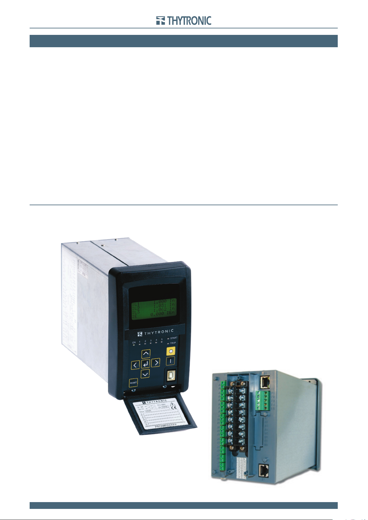
Photo

11
11 NG10 - Manual - 01 - 2015 GENERAL
Main features
• Metallic case.
• Backlight LCD 4x16 Display.
• Eight LEDs that may be joined with matrix criteria to many and various functions.
• RESET key to clear LED indications and latched output relays.
• Two free settable binary inputs.
• Independently settable for start, trip, self-test and control six output relay (K1...K6) Each output
relay may be set with normally energized or normally de-energized operating mode and manual or
automatic reset (latched/no-latched).
• Rear Ethernet communication port, with MODBUS TCP/IP® protocol, with RJ45 (copper wires) or
FX (optical fiber) connection.
• Rear RS485 port, with ModBus protocol.
• USB front serial port (local communication for ThyVisor).
• Real time clock with super capacitor.
The most significant constructive features are:
• Galvanically insulated input and output circuits (communication and binary circuits included).
• Optimum filtering of input signals through combined use of analog and digital filters.
• Traditional electromechanical-type final output contacts with continuous monitoring of control coil
continuity.
• Auxiliary supply comprising a switching-type voltage stabilizing circuit having a very wide working
range and a very small power dissipation
• Nominal frequency: 50 or 60 Hz.
The most significant operating features are:
• Programming of operating modes and parameters by means of the front keys and alphanumeric
display, with a programming procedure based on carrying out guided selections and on explicit and
immediate signalling of the operations being performed, so that such procedure can be carried out
without coding tables or mnemonic informations.
• The feature modification operations do not interrupt the normal functions of the relay.
• Impossibility of programming unacceptable parameter values, thanks to the automatic limitation of
top and bottom scale values for the relative setting ranges.
• Currents are sampled 24 times per period and measured in the effective value (RMS) of the funda-
mental component using the DFT (Discrete Fourier Transform) algorithm and digital filters.
• The fault recorder (SFR) runs continuously capturing in circular mode the last twenty events upon
trigger of binary input/output and/or element pickup (start-trip).
• The event recorder (SER) runs continuously capturing in circular mode the last three hundred
events upon trigger of binary input/output.
• Recording of the last setting changes (Logger).
• Digital fault recorder (DFR) in COMTRADE format (oscillography).

TECHNICAL DATA 12
NG10 - Manual - 04 - 2022
3 TECHNICAL3 TECHNICAL DATADATA
3.1 GENERAL
Product standard for measuring relays
Reference standards IEC 60255-1 Part 1: Common requirements
Mechanical data
Mounting:
• Flush.
• Projecting.
• Rack.
• Separated operator panel.
External dimensions (Flush mounting) 177 x 107 x 235 (high x width x depth)
Terminals screw connection
Mass (Flush mounting) 2.0 kg
Reference standards EN 60529, EN 60529/A1
Degrees of protection provided by enclosures (IP Code)
• Front IP52
• Terminals IP20
Insulation
Reference standards EN 60255-5, IEC 60255-27
High voltage test (50 Hz - 60 s)
• Auxiliary power supply 2 kV
• Input circuits 2 kV
• Output circuits 2 kV
• Output circuits (between open contacts) 1 kV
Impulse voltage withstand test (1.2/50 µs):
• Auxiliary power supply 5 kV (Common mode) - 2kV (Differential mode)
• Input circuits 5 kV
• Output circuits 5 kV
• Output circuits (between open contacts) 1 kV
• Comunication Circuits 500 V
Insulation resistance >100 MW
Voltage dip and interruption
Reference standards EN 61000-4-29, IEC 60255-22-11
Voltage dips, short interruptions and voltage variations on dc input power port immunity tests
• Interruption (UT=40%) 100 ms
• Interruption (UT=0%) 50 ms
• Voltage variations (UT=80...120%) 10 s
EMC tests for interference immunity
Reference standards IEC 60255-26, EN 60255-26
Product standard for measuring relays
Generic standards immunity for industrial environments EN 61000-6-2
• Electromagnetic compatibility requirements for measuring relays and protection equipment
Apparati di automazione e controllo per centrali e stazioni elettriche
• Compatibilità elettromagnetica - Immunità ENEL REMC 02
• Normativa di compatibilità elettromeccanica per apparati e sistemi
ENEL REMC 01
Reference standards EN 60255-22-1 IEC 60255-22-1
EN 61000-4-12 EN 61000-4-12
Damped oscillatory wave
• 0.1 MHz and 1 MHz common mode 2.5 kV
• 0.1 MHz and 1 MHz differential mode 1.0 kV
• Ring wave common mode 2.0 kV
• Ring wave differential mode 1.0 kV
Reference standards EN 60255-22-2 IEC 60255-22-2
EN 61000-4-2 IEC 61000-4-2
Electrostatic discharge
• Contact discharge 6 kV
• Air discharge 8 kV
Reference standards EN 60255-22-3 IEC 60255-22-3
EN 61000-4-3 IEC 61000-4-3
Radiated radio-frequency fields
• 80...1000 MHz AM 80% 10 V/m

TECHNICAL DATA 13
NG10 - Manual - 04 - 2022
• 900 MHz Pulse modulated 10 V/m
Reference standards EN 60255-22-4 IEC 60255-22-4
EN 61000-4-4 IEC 61000-4-4
Fast transient burst (5/50 ns)
• Auxiliary power supply 2 kV
• Input circuits 4 kV
Reference standards EN 60255-22-5 IEC 60255-22-5
EN 61000-4-5 IEC 61000-4-5
High energy pulse
• Uaux (line-to-ground 10 ohm, 9 mF) 2 kV
• Uaux (line-to-line 0 ohm, 18 mF) 1 kV
• I/O ports (line-to-ground 40 ohm, 0.5 mF) 2 kV
• I/O ports (line-to-line 40 ohm, 0.5 mF) 1 kV
Reference standards EN 60255-22-6 IEC 60255-22-6
EN 61000-4-6 IEC 61000-4-6
Conducted radio-frequency fields
• 0.15...80 MHz AM 80% 1kHz 10 V
Reference standards EN 60255-22-7 IEC 60255-22-7
EN 61000-4-16 IEC 61000-4-16
Power frequency immunity tests
• Dc voltage 30 V
• 50 Hz continuously 30 V
• 50 Hz 1 s 300 V
• 0.015...150 kHz 30 V
Reference standards EN 61000-4-8 IEC 61000-4-8
Magnetic field 50 Hz
• 50 Hz continuously 100 A/m
• 50 Hz 1 s 1 kA/m
Reference standards EN 61000-4-10 IEC 61000-4-10
Damped oscillatory magnetic field
• Damped oscillatory wave 0.1 MHz 30 A/m
• Damped oscillatory wave 1 MHz 30 A/m
Emission
Reference standards EN 60255-25 IEC 60255-25
EN 61000-6-4 IEC 61000-6-4
EN 55011 CISPR 11
Electromagnetic emission tests
• Conducted emission auxiliary power supply 0.15...0.5 MHz 79 dB mV
• Conducted emission auxiliary power supply 0.5...30 MHz 73 dB mV
• Radiated emission 30...230 MHz 40 dB mV/m
• Radiated emission 230...1000 MHz 47 dB mV/m
Mechanical tests
Reference standards EN 60255-21-1 EN 60255-21-2 RMEC01
Vibration, shock, bump and seismic tests on measuring relays and protection equipment
• EN 60255-21-1 Vibration tests (sinusoidal) Class 1
• EN 60255-21-2 Shock and bump test Class 1
Climatic tests
Reference standards IEC 60068-x ENEL R CLI 01 CEI 50
Environmental testing
Ambient temperature -25...+70 °C
Storage temperature -40...+85 °C
Relative humidity 10...95 %
Atmospheric pressure 70...110 kPa
Safety
Reference standards IEC 60255-27
Safety requirements for electrical equipment for measurement, control and laboratory use
Pollution degree 3
Reference voltage 250 V
Overvoltage category III
Certifications
Reference standards
Product standard for measuring relays EN 50263
CE Conformity
• EMC Directive 2014/30/EC
• Low Voltage Directive 2014/35/EC

TECHNICAL DATA 14
NG10 - Manual - 04 - 2022
Type tests IEC 60255-1
3.2 INPUT CIRCUITS
Auxiliary power supply Uaux
Voltage
Nominal value (range)[1] 24...48 V~/- or 115...230 V~/110...220 V-
Operative range (each one of the above nominal values) 19...60 V~/- or 85...265 V~/75...300 V-
Inrush current (max)
• 24 V- 6 A, 5 ms
• 48 V- 14 A, 5 ms
• 110 V- 20 A, 1 ms
• 230 V~ 50 A, 1 ms
Frequency (for alternate voltage supply) 45...66 Hz
Max distortion factor ( for alternating voltage supply) 15%
Max alternating component (for dc voltage supply):
• Full wave rectified sine wave 100 %
• Sine wave 80 %
Power consumption:
• Maximum (energized relays, Ethernet TX) 10 W (20 VA)
• Maximum (energized relays, Ethernet FX) 15 W (25 VA)
Phase current input circuits (side H and side L)
Relay nominal phase current InH and InL 1 A or 5 A selectable by dip-switch
Permanent overload 25 A
Thermal overload (1 s) 500 A
Dynamic overload (half cycle) 1250 A
Rated consumption (for any phase) ≤0.002 VA with InH or InH = 1 A
≤0.04 VA with InH or InH = 5 A
Residual current input circuit
Relay nominal residual current IEn 1 A or 5 A selectable by dip-switch
Permanent overload 25 A
Thermal overload (1 s) 500 A
Dynamic overload (half cycle) 1250 A
Rated consumption ≤0.006 VA with IEn = 1 A
≤0.12 VA with IEn = 5 A
Binary input circuits
Quantity 2
Type optocoupler
Operative range 24...265 V~/-
Min activation voltage 18 V
Max consumption, energized 3 mA
ON delay time OFF->ON (IN1 tON, IN2 tON)0.00...100.0 s
0.00...9.99 s
10.0...100.0 s
OFF delay time ON->OFF (IN1 tOFF, IN2 tOFF)0.00...100.0 s
0.00...9.99 s (step 0.01 s)
10.0...100.0 s (step 0.1 s)
Block input (Logic selectivity)
Quantity 1
Type polarized wet input (powered by internal isolated supply)
Max consumption, energized 5 mA
3.3 OUTPUT CIRCUITS
Relays
Quantity 6
Type of contacts K1, K2 changeover (SPDT, type C)
Type of contacts K3, K4, K5 make (SPST-NO, type A)
Type of contacts K6 break (SPST-NC, type B)
Nominal current 8 A
Nominal voltage/max switching voltage 250 V~/400 V~
Breaking capacity:
• Direct current (L/R = 40 ms) 50 W
• Alternating current (l= 0,4) 1250 VA
Make 1000 W/VA
Short duration current (0,5 s) 30 A
Minimum switching load 300 mW (5 V/ 5 mA)
Life:
• Mechanical 106operations
• Electrical 105operations
Note 1 Version must be selected at ordering

TECHNICAL DATA 15
NG10 - Manual - 04 - 2022
Minimum pulse width 0...0.500 s (step 0.005 s)
Block output (Logic selectivity)
Quantity 1
Type optocoupler
3.4 MMI
Display 16 x 4 alphanumeric LCD
LEDs
Quantity 8
• ON/fail (green) 1
• Start (yellow) 1
• Trip (red) 1
• Freely allocatable (red) 5
Keyboard 8 keys
3.5 COMMUNICATION INTERFACES
Local port
Connection USB Type B
Protocol Modbus RTU®
Remote ports
RS485
• Connection screw terminals
• Baud rate 1200...57600 bps
• Protocol[1] ModBus®RTU
IEC 60870-5-103
DNP3
Ethernet 100BaseT
• Connection[2] Optical fiber 1300 nm, ST
100 Base TX, RJ45
• Baud rate 100 Mbps
• Protocol ModBus®TCP/IP
Note 1 Different version must be selected at ordering
Note 2 Different version must be selected at ordering

TECHNICAL DATA 16
NG10 - Manual - 04 - 2022
3.6 GENERAL SETTINGS
Rated values (Base)
Relay nominal frequency (fn) 50, 60 Hz
Relay phase nominal current side H and L (InH and InH) 1 A or 5 A [1]
Phase CT primary nominal current side H and L (InpH and InpH) 1 A...20.0 kA
1...499 A (step 1 A)
500...4990 A (step 10 A)
5000...20000 A (step 100 A)
Relay residual nominal current (IEn) 1 A o 5 A [1]
Residual CT primary nominal current (IEnp) 1 A...20.0 kA
1...499 A (step 1 A)
500...4990 A (step 10 A)
5000...20000 A (step 100 A)
Protected device nominal current (Ing) 1 A...20 kA
1...499 A (step 1 A)
500...4990 A (step 10 A)
5000...20000 A (step 100 A)
Primary nominal current chosen as referrence (Inref)[2] - A
Lato di riferimento per la compensazione (Refsize)[2] -
Current matching type (MatchType) INTERNAL/EXTERNAL
Protected object by differential protection (ProtObj) GEN-MOT-LINE-BAR
Input sequence [3]
Phase current sequence side H (I-SequenceH) IL1-IL2-IL3 Default
IL1-IL3-IL2
IL2-IL1-IL3
IL2-IL3-IL1
IL3-IL1-IL2
IL3-IL2-IL2
Phase current sequence side L (I-SequenceL) IL1-IL2-IL3 Base
IL1-IL3-IL2
IL2-IL1-IL3
IL2-IL3-IL1
IL3-IL1-IL2
IL3-IL2-IL2
Polarity [3]
C09-C10 (IL1H) terminal polarity (C09-C10 POL) NORMAL/REVERSE
C11-C12 (IL2H) terminal polarity (C11-C12 POL) NORMAL/REVERSE
C13-C14 (IL3H) terminal polarity (C13-C14 POL) NORMAL/REVERSE
C15-C16 (IE1) terminal polarity(C15-C16 POL)NORMAL/REVERSE
C01-C02 (IL1L) (terminal polarity C01-C02 Pol) NORMAL/REVERSE
C03-C04 (IL2L) terminal polarity (C03-C04 POL) NORMAL/REVERSE
C05-C06 (IL3L) terminal polarity (C05-C06POL) NORMAL/REVERSE
C07-C08 (IL3L) terminal polarity (C07-C08POL) NORMAL/REVERSE
Note 1 The nominal current settings doesn’t concern the protection elements; they must agree with hardware setting (dip-switch 1 A or 5 A) .
Note 2 Calculated by relay (L or H)
Nota 3 Adjusting enabled by working with session-level 1

TECHNICAL DATA 17
NG10 - Manual - 04 - 2022
3.7 PROTECTIVE FUNCTIONS
Thermal protection with Pt100 probes - 26[1]
ThAL1...8 Alarm:
Alarm threshold 26 PT1...PT8 (ThAL1...8) 0...200 °C
Operating time ThAL1...8 (tThAL1...8) 0....100 s
Th>1...8 Trip:
Trip threshold 26 PT1...PT8 (Th>1...8) 0...200 °C
Operating time ThAL1...8 (tTh>1...8)0....100 s
Residual overcurrent or high impedance differential restricted ground fault - 50N/51N - 87NHIZ
IE> Element
IE> Curve type (IE>Curve)DEFINITE
IEC/BS A, B, C
ANSI/IEEE MI, VI, EI
EM
IE> Reset time delay (tE>RES)0.00...100.0 s
0.00...9.99 s (step 0.01 s)
10.0...100.0 s (step 0.1 s)
Definite time
50N/51N First threshold definite time (IE>def) 0.005...10.00 IEn
0.005...0.999 IEn (step 0.001 IEn)
1.00...10.00 IEn (step 0.01 IEn)
IE>def Operating time (tE>def) 0.04...200 s
0.04...9.99 s (step 0.01 s)
10.0...99.9 s (step 0.1 s)
100...200 s (step 1 s)
Inverse time[2]
50N/51N First threshold inverse time (IE>inv) 0.005...2.00 IEn
0.005...0.999 IEn (step 0.001 IEn)
1.00...2.00 IEn (step 0.01 IEn)
IE>inv Operating time (tE>inv) 0.02...60.0 s
0.02...9.99 s (step 0.01 s)
10.0...60.0 s (step 0.1 s)
IE>> Element
IE>> Reset time delay (tE>>RES)0.00...100.0 s
0.00...9.99 s (step 0.01 s)
10.0...100.0 s (step 0.1 s)
Definite time
50N/51N Second threshold definite time (IE>>def) 0.005...10.00 IEn
0.005...0.999 IEn (step 0.001 IEn)
1.00...10.00 IEn (step 0.01 IEn)
IE>>def Operating time (tE>>def) 0.03...10.00 s (step 0.01 s)
IE>>> Element
IE>>> Reset time delay (tE>>>RES)0.00...100.0 s
0.00...9.99 s (step 0.01 s)
10.0...100.0 s (step 0.1 s)
Definite time
50N/51N Third threshold definite time (IE>>>def) 0.005...10.00 IEn
0.005...0.999 IEn (step 0.001 IEn)
1.00...10.00 IEn (step 0.01 IEn)
IE>>>def Operating time (tE>>>def) 0.03...10.00 s (step 0.01 s)
Pickup time ≤ 0.03 s
Dropout ratio 0.95...0.98
Dropout time ≤ 0.04 s
Overshoot time 0.03 s
Pickup accuracy ± 4% ± 1% IEn
Operate time accuracy 5% or ± 10 ms
Note 1 The 26 element is available when the MPT module is connect on Thybus and enabled
Note2 Standard Inverse Time (IEC 255-3/BS142 type A or SIT): t = 0.14 · tE1>inv / [(IE/IE>inv)0.02 - 1]
Very Inverse Time (IEC 255-3/BS142 type B or VIT): t = 13.5 · tE1>inv / [(IE/IE>inv) - 1]
Extremely Inverse Time (IEC 255-3/BS142 type C or EIT): t = 80 · tE1>inv / [(IE/IE>inv)2 - 1]
Moderately Inverse (ANSI/IEEE type MI): t = tE1>inv · {0.01 / [(IE/IE>inv)0.02 - 1] + 0.023}
Very Inverse (ANSI/IEEE type VI): t = tE1>inv · {3.922 / [(IE/IE>inv)2- 1] + 0.098}
Extremely Inverse (ANSI/IEEE type EI): t = tE1>inv · {5.64 / [(IE/IE>inv)2- 1] + 0.024}
Electromechanical (EM): t = 0.28 · tE>inv / [-0.236 · (IE/IE>inv)-1+ 0.339]
t:operate time
tE1>inv:operate time setting
IE1>inv: threshold setting
IE1:residual current input (measured at IE1 input)
Asymptotic reference value: 1.1 IE1>inv
Minimum operate time: 0.1 s
Equation is valid for: 1.1 ≤ IE/IE>inv ≤ 20; with IE1>inv setting ≥ 0.5 IE1n, the upper limit is 10 IE1n

TECHNICAL DATA 18
NG10 - Manual - 04 - 2022
Low impedance restricted ground fault - 64REF side H
64REF) Minimum threshold (IREF>) 0.05...2.00 IEn (step 0.01 IEn)
64REF Intentional delay (tREF>) 0.03...60.00 s (step 0.01 s)
Pickup time ≤ 0.04 s
Dropout ratio 0.95...0.98
Dropout time ≤ 0.05 s
Overshoot time 0.04 s
Pickup accuracy ± 4% with 0.1 In, ±1% with 1 In
Operate time accuracy 5% or ± 10 ms
Differential - 87G-M-L
CT saturation detector
87G-M-L Saturation detector enable (Sat-Det) ON/OFF
87T Saturation detector intentional reset time delay (tSat-Det-RES) 0.00...0.50 s (step 0.01 s)
Id> Element
87G-M-L First threshold (
I
d>) 0.05...2.00 Inref (step 0.01 Inref)
87G-M-L First stretch slope percentage (
K1
) 10...50% (step 1 %)
87G-M-L Second branch slope percentage (
K2
) 25...100% (step 1 %)
87G-M-L Second branch intersection with vertical axis (
Q
) 0.00...3.00 Inref (step 0.01 Inref)
87G-M-L First threshold operating time
I
d>(td>) 0.04 s
Id>> Element
87G-M-L Second threshold (
I
d>>) 0.50...30.00 Inref (step 1.00 Inref)
87G-M-L Second threshold operating time
I
d>> (td>>) 0.03 s
Breaker failure - BF
BF Phase current threshold (IBF>) 0.05...1.00 In (step 0.01 In)
BF Operating time (tBF) 0.06...10.00 s (step 0.01 s)
Dropout ratio 0.95...0.98
Dropout time ≤ 0.05 s
IBF>Pickup accuracy ± 0.5% with 0.1 In
± 0.2% with 1 In
IEBF>Pickup accuracy ± 0.5% with 0.01 IEn
± 0.2% with 1 IEn
Operate time accuracy 5% or ± 10 ms

TECHNICAL DATA 19
NG10 - Manual - 04 - 2022
3.8 CONTROL AND MONITORING
Trip Circuit Supervision side H and side L - 74TCS
Operate time:
• One binary input supervision 40 s
• Two binary inputs supervision 2 s
Reset time delay:
• One binary input supervision 6 s
• Two binary inputs supervision 0.6 s
Selective block - BLOCK2
Selective block IN:
• BLIN Selective block operating mode (ModeBLIN1) OFF-ON IPh/IE-ON IPh-ON IE
• BLIN maximum activation time for phase protections (tB-IPh) 0.10...10.00 s (step 0.01 s)
• BLIN maximum activation time for ground protections (tB-IE) 0.10...10.00 s (step 0.01 s)
Selective block OUT:
• BLOUT Selective block operating mode (ModeBLOUT1) OFF-ON IPh/IE-ON IPh-ON IE
• BLOUT Dropout time for phase protections (tF-IPh) 0.00...1.00 s (step 0.01 s)
• BLOUT Dropout time for ground protections (tF-IE) 0.00...1.00 s (step 0.01 s)
• BLOUT Dropout time for ground and phase protections (tF-IPh/IE) 0.00...1.00 s (step 0.01 s)
Circuit Breaker supervision
Circuit breaker diagnostic
Number of CB trips threshold (CB N.Open) 0...10000 (step 1)
Cumulative CB tripping currents threshold (CB SumI)0....5000 In (step 1 In)
Cumulative CB tripping I2t threshold (CB SumI^2t)0....5000 (In)2∙s (step 1 In2∙s)
Circuit Breaker opening time for I^2t calculation (CB tbreak) 0.05...1.00 s (step 0.01 s)
Circuit Breaker maximum allowed opening time (CB tbreak>) 0.05...1.00 s (step 0.01 s)
CT supervision - 74CT side H
74CT(H) Threshold (S(H)<) 0.10...0.95 (step 0.01)
74CT(H) Overcurrent threshold 74CT (I(H)*)0.10...1.00 InH (step 0.01 InH)
S(H)< Operating time (tS(H)<) 0.03...200 s
0.03...9.99 s (step 0.01 s)
10.0...99.9 s (step 0.1 s)
100...200 s (step 1 s)
Dropout ratio for the I(H)* pickup 0.95...0.98
Dropout time ≤ 0.05 s
Pickup accuracy S(H)< ± 1% with 0.1 InH , ± 0.5% with 1 InH
Pickup accuracy I(H)* ± 0.5% with 0.1 InH , ± 0.2% with 1 InH
Operate time accuracy 5% or ± 10 ms
CT supervision - 74CT side L
74CT(L) Threshold (S(L)<) 0.10...0.95 (step 0.01)
74CT(L) Overcurrent threshold 74CT (I(L)*)0.10...1.00 InL (step 0.01 InL)
S(L)< Operating time (tS(L)<) 0.03...200 s
0.03...9.99 s (step 0.01 s)
10.0...99.9 s (step 0.1 s)
100...200 s (step 1 s)
Dropout ratio for the I(L)* pickup 0.95...0.98
Dropout time ≤ 0.05 s
Pickup accuracy S(L)< ± 1% with 0.1 InL , ± 0.5% with 1 InL
Pickup accuracy I(L)* ± 0.5% with 0.1 InL , ± 0.2% with 1 InL
Operate time accuracy 5% or ± 10 ms
Pilot wire diagnostic
• BLOUT1 Diagnostic pulse period (PulseBLOUT1) OFF-0.1-1-5-10-60-120 s
• BLIN1 Diagnostic pulse control time interval (PulseBLIN1) OFF-0.1-1-5-10-60-120 s
Demand measures
• Fix on demand period (tFIX) 1...60 min (step 1 min)
• Rolling on demand period (tROL) 1...60 min (step 1 min)
• Number of cycles for rolling on demand (N.ROL) 1...24 (step 1)

TECHNICAL DATA 20
NG10 - Manual - 04 - 2022
Oscillography (DFR)[1]
Format COMTRADE
Recording mode circular
Sampling rate 16 samples / cycle
Trigger setup:
• Pre-trigger time 0.05...1.00 s (step 0.01 s)
• Post-trigger time 0.05...60.00 s (step 0.05 s)
Set sample channels:
iL1H, iL2H, iL3H, iL1L, iL2L, iL3L, iE,iL1cH,
iL2cH, iL3cH, iL1cL, iL2cL,
iL3cL, iSL1, iSL2, iSL3, idL1, idL2, idL3,
Set analog channels:
Analog 1...Analog 12 IL1H, IL2H, IL3H, IL1L, IL2L, IL3L,
IE, IL1cH, IL2cH, IL3cH, IL1cL, IL2cL,
IL3cL,ISL1, ISL2, ISL3, IdL1, IdL2, IdL3,
IE, IESH,T1...T8[2]
Set digital channels:
Digital 1...Digital 16 K1... K6, K7...K10,
IN1, IN2, IN3...IN42[3]
Set digital channels from 87G-M-L states
(Digital 17...32)
• Start states ST Id>-L1...L3, ST Id>>-L1...L3, ST
2nd-REST, ST 5th-REST, ST H-REST-L1...
L3, ST satDet
• Trip states TR Id>-L1...L3, TR Id>>-L1...L3
PLC (Programmable Logic Controller)[4]
Reference standard IEC 61131-3
Language[5] IL (Instruction List)
Inputs:
Binary inputs IN1, IN2 on board
IN8...IN10 with MRI module
IN11...IN26 with one MID16 module
IN27...IN42 with two MID16 modules
Delayed binary inputs[6] IN1, IN2 on board
IN8...IN10 with MRI module
IN11...IN26 with one MID16 module
IN27...IN42 with two MID16 modules
Start (all elements) Start U<, Start U<<,...etc
Trip (all elements) Trip U<, Trip U<<,...etc
Measures IL1, IL2,...ecc
Temperature Pt100
Block inputs BLK2IN-Iph, BLK2IN-IE,...etc
Outputs:
Relays K11...K6 on board
K7...K10 with MRI module
LEDs START, TRIP, L1...L6 on board
L7...L10 with MRI module
Block outputs BLK2OUT-Iph, BLK2OUT-IE,...etc
Current converter DAC
Note 1 For the DFR function a licence is required; call Thytronic for purchasing.
Note 2 The measures of temperature are available only when the MPT module on Thybus is enabled (eigth Pt100 inputs)
Note 3 Output relay K7...K10 and binary input IN3...IN42 states are available only when the concerning I/O circuits are implemented (MRI and MID16
modules on Thybus)
Note 4 For the PLC function a licence is required; call Thytronic for purchasing.
Note5 With ThyVisor V3.4.3 release and compiler IEC 61131-3 V1.2.7 only the IL language is implemented (Instruction List);
other languages, according with IEC 61131 standard (ST (Structured Text)), LD (Ladder Diagram), FBD (Function Block Diagram), SFC (Sequential
Functional Chart), will be available soon
Note 6 The input state is acquired downstream the tON and tOFF timers
Table of contents
Other Thytronic Protection Device manuals


Popular Protection Device manuals by other brands

AAK Safety
AAK Safety Smartline Instructions for use

Daniamant
Daniamant LJ2 Installation and maintenance instructions

dehn
dehn DCU YPV SCI 1000 1M installation instructions

Cobra
Cobra ELITE DUALPRO 360 owner's manual

Merlin Gerin
Merlin Gerin Sepam series 20 Quick start quide

KELCO
KELCO IPG20 MK3 Installation & programming manual


Innotech
Innotech AIO-GLEIT-13 instruction manual

nVent RAYCHEM
nVent RAYCHEM WinterGard Mesh Operation manual

ABB
ABB Relion REG670 Technical manual

Silverline
Silverline MICE & RAT FREE 25 manual

Siemens
Siemens 7SR242 Duobias Technical manual

Cardin Elettronica
Cardin Elettronica SEL Series quick start guide