5
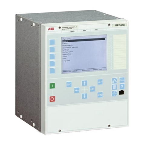
Legenda
1 Dip-switch predisposizione soglia di intervento della protezione
I>
2 Dip-switch predisposizione temporizzazione K della protezione
I>
3 Dip-switch predisposizione tipo di curva (DT, NI, VI, EI) della
protezione I>
4 Dip-switch predisposizione soglia di intervento protezione I>>
5 Dip-switch predisposizione tempo di intervento t>> protezione
I>>
6 Bandierina magnetica bistabile di segnalazione protezione I> o
I>> intervenuta
7 Led di segnalazione temporizzazione in corso protezioni I> o
I>>
16 Relazione tempo-corrente secondo IEC 255-4
17 Display visualizzante la corrente della fase più caricata
18 Bandierina magnetica bistabile segnalazione di avvenuta aper-
tura a distanza dell'interruttore
19 Pulsante di RESET del microprocessore e dei relè bistabili di
segnalazione SRE e µP FAULT
20 Pulsante di reset delle bandierine magnetiche bistabili (rif. 6, 18)
21 Led di segnalazione microprocessore guasto (µP FAULT)
27 Dip-switch predisposizione calibro trasformatori amperometrici
28 Tappo copri dip-switch e targhetta “In” calibro TA
29 Nr. di matricola unità
30 Connettore per TEST
Caption
1 Dip-switch for setting the tripping threshold of protection I>
2 Dip-switch for setting the time-delay K of protection I>
3 Dip-switch for setting the type of curve (DT, NI, VI, EI) of
protection I>
4 Dip-switch for setting the trip threshold of protection I>>
5 Dip-switch for setting the trip time t>> of protection I>>
6 Bistable magnetic flag indicating protection I> or I>> tripped
7 LED indicating time-delay elapsing protection I> or I>>
16 Time-current relation in conformity with IEC 255-4
17 Display showing the phase current with the highest load
18 Bistable magnetic flag indicating remote opening of circuit-
breaker
19 RESET pushbutton for microprocessor and bistable relays
signalling SRE and µP FAULT
20 Reset pushbutton for bistable magnetic flags (refs. 6, 18)
21 LED indicating microprocessor fault (µP FAULT)
27 Dip-switch for setting rated current of current transformers
28 Dip-switch and CT “In” setting plate cover
29 Unit serial number
30 TEST connector
2. Trasformatori amperometrici di fase
Tutte le operazioni di programmazione, devono es-
sere effettuate da personale con una qualifica suffi-
ciente e una conoscenza adeguata dell’apparec-
chiatura.
Scollegare l’unità PR512 prima di effettuare qualsi-
asi prova di isolamento sull’impianto.
Nelcasoincuilacorrentenominaledell’interruttore
siaminoredellacorrente nominale del trasformato-
re amperometrico (esempio: interruttore HD4 da
630 A con TA da 1250 A) è obbligatorio predisporre
la funzione 51 e 51N (I> e Io>) in modo tale da NON
SUPERARElaportataamperometricanominaledel-
l’interruttore controllato (nel ns. esempio il valore
massimo è I> = 0,5 e Io> = 0,5).
I trasformatori amperometrici di fase connessi all'unità svolgo-
no due funzioni:
a) fornire l'energia necessaria al corretto funzionamento;
b) fornire il segnale necessario al rilevamento della corrente.
Il PR512/P può essere impiegato con otto diversi TA, caratte-
rizzati dai seguenti valori:
– Corrente nominale secondaria 1 A
– Prestazione 2,5 VA
– Precisione 5 P 10
– Fattore di sicurezza 15
– Prestazione termica Ith = 25 kA x 1s a 50 Hz
– Frequenza di lavoro 50-60 Hz
– Per la corretta lettura dell'amperometro è necessario abbina-
re TA con le seguenti correnti nominali primarie:
40 A, 80 A, 100 A, 150 A, 200 A, 250 A, 600 A, 1250 A.
Sul fronte dell'unità è possibile selezionare i dip-switch, relativi
ai TA montati (fig. 1 - rif. 27), nel seguente modo:
2. Phasecurrenttransformers
Alltheprogrammingoperationsmustbecarriedout
by suitably qualified personnel with adequate
knowledge of the apparatus.
Disconnect the PR512 unit before carrying out any
insulationtest ontheinstallation.
Whentheratedcurrentofthecircuit-breakerislower
than the rated current of the current transformer
(e.g.:HD4630 Acircuit-breakerwith 1250ACT), itis
compulsory to provide function 51 and 51N (I> and
Io>) so that the rated current capacity of the circuit-
breaker controlled is NOT EXCEEDED (in our
example,themaximumvalueisI>=0.5andIo>=0.5).
The phase current transformers connected to the unit carry out
the following two functions:
a) they supply the energy required for correct operation;
b) they supply the signal required to sense the current.
The PR512/P can be used with eight different CTs, character-
ized by the following values:
– Rated secondary current 1 A
– Performance 2.5 VA
– Precision 5 P 10
– Safety factor 5
– Thermal performance Ith = 25 kA x 1s a 50 Hz
– Operating frequency 50-60 Hz
– For correct ammeter readout, the CT must be combined with
the following rated primary currents:
40 A, 80 A, 100 A, 150 A, 200 A, 250 A, 600 A, 1250 A.
The dip-switches - relative to the CTs mounted (fig. 1 - ref. 27)
- can be selected on the front of the unit as follows:
TA
40A TA
80A TA
150A
TA
200A TA
250A TA
1250A
TA
600A
TA
100A
!!
