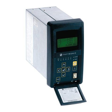
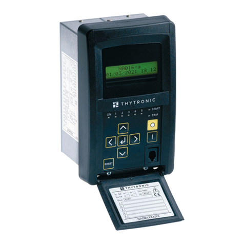
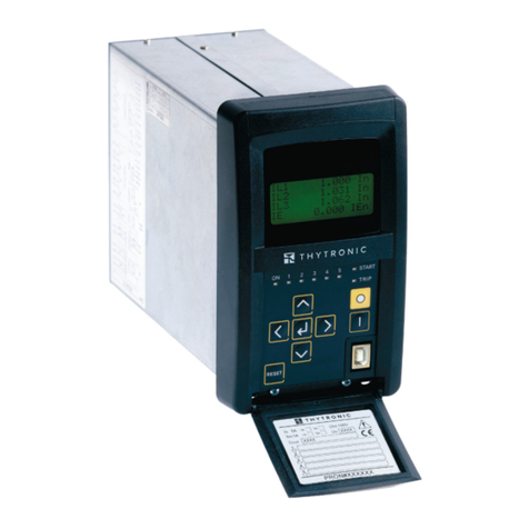
Thytronic SIF5600 User manual

SIF5600 - Manual - 03 - 2008
CERTIFIED
DK5600
SIF5600
OVERCURRENT AND GROUND FAULT
PROTECTION RELAY
&
CB
COMMAND
KEYLOCK

22SIF5600 - Manual - 03 - 2008
CONTENTS
1 INTRODUCTION 5
Scope.................................................................................................................................................................................................................5
Applicability......................................................................................................................................................................................................5
Conformity.........................................................................................................................................................................................................5
Technical support............................................................................................................................................................................................5
Copyright...........................................................................................................................................................................................................5
Warranty ...........................................................................................................................................................................................................5
Safety recommendations...............................................................................................................................................................................5
Insulation tests.................................................................................................................................................................................................5
Identification ....................................................................................................................................................................................................6
Current connections .......................................................................................................................................................................................6
Environmental Conditions ..............................................................................................................................................................................6
Symbols.............................................................................................................................................................................................................6
Abbreviations/definitions...............................................................................................................................................................................6
1 INTRODUCTION 7
Preface..............................................................................................................................................................................................................7
Main characteristics.......................................................................................................................................................................................8
3 TECHNICAL DATA 9
3.1 GENERAL..............................................................................................................................................................................................................9
Mechanical data..............................................................................................................................................................................................9
Insulation test...................................................................................................................................................................................................9
EMC tests..........................................................................................................................................................................................................9
Voltage dip and interruption ..........................................................................................................................................................................9
EMC tests for interference immunity ...........................................................................................................................................................9
Emission tests ................................................................................................................................................................................................10
Climatic tests..................................................................................................................................................................................................10
Mechanical tests...........................................................................................................................................................................................10
Safety...............................................................................................................................................................................................................10
Other standards.............................................................................................................................................................................................10
3.2 INPUT CIRCUITS ...............................................................................................................................................................................................11
Auxiliary power supply.................................................................................................................................................................................11
Phase current input circuits........................................................................................................................................................................11
Residual current input circuit......................................................................................................................................................................11
Binary input circuits......................................................................................................................................................................................11
Block input circuits .......................................................................................................................................................................................11
3.3 OUTPUT CIRCUITS............................................................................................................................................................................................11
Output relays..................................................................................................................................................................................................11
Block output circuits.....................................................................................................................................................................................11
3.4 ENVIRONMENTAL CONDITION......................................................................................................................................................................12
3.5 MMI.....................................................................................................................................................................................................................12
3.6 COMMUNICATION INTERFACE......................................................................................................................................................................12
Local Port........................................................................................................................................................................................................12
3.7 GENERAL SETTINGS ........................................................................................................................................................................................12
3.8 PROTECTION AND CONTROL FUNCTIONS ..................................................................................................................................................12
Phase overcurrent (50/51)............................................................................................................................................................................12
Residual overcurrent (50N-51N) .................................................................................................................................................................13
Blocking function...........................................................................................................................................................................................13
4 FUNCTION PRINCIPLE 14
4.1 HARDWARE .......................................................................................................................................................................................................14
Power supply board......................................................................................................................................................................................14
Processing board ..........................................................................................................................................................................................14
4.2 SOFTWARE.........................................................................................................................................................................................................15
Kernel ..............................................................................................................................................................................................................15
Drivers.............................................................................................................................................................................................................15
Application......................................................................................................................................................................................................15
Base protocol (kernel)..................................................................................................................................................................................15
Calibration (kernel)........................................................................................................................................................................................15
Communication (drivers)..............................................................................................................................................................................16
MMI (drivers) .................................................................................................................................................................................................16
Data Base (application/drivers)..................................................................................................................................................................16
Self-test (application) ...................................................................................................................................................................................16
Development tools.........................................................................................................................................................................................16

3
3
SIF5600 - Manual - 03 - 2008
4.3 FUNCTIONAL DESCRIPTION...........................................................................................................................................................................16
Measurements...............................................................................................................................................................................................16
Counters..........................................................................................................................................................................................................16
Inputs...............................................................................................................................................................................................................16
Identification ..................................................................................................................................................................................................17
Event recorder ...............................................................................................................................................................................................17
Output relays.................................................................................................................................................................................................17
LED indicators................................................................................................................................................................................................18
Communication interfaces...........................................................................................................................................................................19
Self-test...........................................................................................................................................................................................................19
Logic selectivity.............................................................................................................................................................................................20
Binary inputs ..................................................................................................................................................................................................22
Test...................................................................................................................................................................................................................22
Breaker management...................................................................................................................................................................................22
5 INSTALLATION 24
5. PACKAGING.......................................................................................................................................................................................................24
5.2 PROJECTING MOUNTING...............................................................................................................................................................................24
5.3 FLUSH MOUNTING...........................................................................................................................................................................................25
5.4 CORE BALANCE CTS................................................................................................................................................................................................................26
Open type current transformer ...................................................................................................................................................................26
Closed type current transformer - 110 mm diameter...............................................................................................................................27
Closed type current transformer - 200 mm diameter...............................................................................................................................28
5.5 ELECTRICAL CONNECTIONS ..........................................................................................................................................................................29
5.6 SETTING NOMINAL CURRENT.......................................................................................................................................................................31
5.7 FINAL CHECKING..............................................................................................................................................................................................31
6 SETTING AND COMMISSIONING 32
6.1 INTRODUCTION ................................................................................................................................................................................................32
Switch in the OFF position............................................................................................................................................................................32
Switch in the DISPLAY MODE position......................................................................................................................................................32
Switch in the CB MODE position.................................................................................................................................................................33
SIF5600 without display................................................................................................................................................................................33
6.2 SOFTWARE PC (ThySetter)..............................................................................................................................................................................34
ThySetter installation....................................................................................................................................................................................34
Use of the ThySetter .....................................................................................................................................................................................34
ON-LINE MODE..............................................................................................................................................................................................34
Currents...........................................................................................................................................................................................................35
I/O block..........................................................................................................................................................................................................36
Status 52..........................................................................................................................................................................................................36
Counters..........................................................................................................................................................................................................36
Events..............................................................................................................................................................................................................36
Info...................................................................................................................................................................................................................37
Self-test...........................................................................................................................................................................................................38
READING AND MODIFYING SETTINGS (Set) ...........................................................................................................................................39
SET...................................................................................................................................................................................................................39
Base.................................................................................................................................................................................................................39
Relays..............................................................................................................................................................................................................39
50-51.................................................................................................................................................................................................................41
50N-51N...........................................................................................................................................................................................................41
52 Circuit breaker management .................................................................................................................................................................41
Block................................................................................................................................................................................................................42
Store ................................................................................................................................................................................................................42
TEST ROUTINES (Test)..................................................................................................................................................................................42
RESET LEDS/RELAYS (Reset).......................................................................................................................................................................43
CIRCUIT BREAKER COMMAND (Command).............................................................................................................................................43
DATA/TIME SETTING (Time) ........................................................................................................................................................................43
COMMUNICATION PARAMETERS (ModBus slave) ................................................................................................................................44
DEFAULT (Option)...........................................................................................................................................................................................44
File operation mode.......................................................................................................................................................................................44
Drop down menus .........................................................................................................................................................................................44
Procedure.......................................................................................................................................................................................................45
Upgrade...........................................................................................................................................................................................................45
Preferenze ......................................................................................................................................................................................................45
File....................................................................................................................................................................................................................45
6.3 MMI (Man Machine Interface) ......................................................................................................................................................................46
Reading variables (Read).............................................................................................................................................................................46
Setting modifying (Set) .................................................................................................................................................................................46
Test...................................................................................................................................................................................................................47

44SIF5600 - Manual - 03 - 2008
Data/time setting (Time) ...............................................................................................................................................................................47
ModBus slave ................................................................................................................................................................................................47
Escape.............................................................................................................................................................................................................47
6.4 MENU TREE........................................................................................................................................................................................................48
6.5 MAINTENANCE.................................................................................................................................................................................................49
6.6 REPAIRS .............................................................................................................................................................................................................49
6.7 STORAGE............................................................................................................................................................................................................49
7 APPLICATION NOTES 50
7.1 LOGIC SELECTIVITY..........................................................................................................................................................................................50
Breaker failure...............................................................................................................................................................................................51
Short circuiting of pilot wires......................................................................................................................................................................51
Pilot wire breaking ........................................................................................................................................................................................51
Pilot wire connections..................................................................................................................................................................................52
7.2 DK5600 ................................................................................................................................................................................................................53
7.3 COORDINATION ................................................................................................................................................................................................54
Selectivity diagram........................................................................................................................................................................................55
8 APPENDIX 56
8.1 APPENDIX A1 - Inverse time IEC curves .....................................................................................................................................................56
Mathematical formula ..................................................................................................................................................................................56
Phase overcurrent 50/51 - Standard inverse time curve (IEC 60255-3/BS142 type A)......................................................................57
Phase overcurrent 50/51 - Very inverse time curve (IEC 60255-3/BS142 type B) ..............................................................................58
Phase overcurrent 50/51 - Extremely inverse time curve (IEC 60255-3/BS142 type C).....................................................................59
Residual overcurrent 50N/51N - Standard inverse time curve (IEC 60255-3/BS142 type A)............................................................60
Residual overcurrent 50N/51N - Very inverse time curve (IEC 60255-3/BS142 type B) ....................................................................61
Residual overcurrent 50N/51N - Extremely inverse time curve (IEC 60255-3/BS142 type C)...........................................................62
8.2 APPENDIX A2 ..................................................................................................................................................................................................63
CONNECTION DIAGRAMS........................................................................................................................................................................................63
8.3 APPENDIX A3 - SETTING SHEET ...................................................................................................................................................................69
8.4 APPENDIX A4 - MODBUS PROTOCOL ..........................................................................................................................................................71

5
5
SIF5600 - Manual - 03 - 2008
1 I N T R O D U C T I O N
Scope
This document describes the technical characteristics of the SIF5600 digital protection relay, illus-
trating its functions and outlining all the instructions necessary for its assembly, adjustment and
start-up.
The manual includes a description of the Modbus messages and the map of the relevant addresses.
This document is updated periodically, information pertaining to revisions is represented by the issue
date.
Users suggestions for improving the document and any corrections are very welcome
Applicability
This document relates to SIF5600 versions with or without displays having:
- firmware release 2.10 and references for 2.00 release (inverse time curves inside Appendix 8)
- MODBUS messages 1.00 release
Conformity
The product complies with EU directives pertaining to:
- EMC directive 89/336/EEC
- LV directive 73/23/EEC
Technical support
Contacs: THYTRONIC Technical service www.thytronic.it
Copyright
All rights reserved; reproduction of any documentation without explicit authorisation from Thytronic,
as well as copying or altering the firmware and corresponding software is strictly forbidden.
Warranty
The product is covered by one year warranty.
Safety recommendations
Users are strongly recommended to comply with the instructions contained in the following docu-
ment; particularly, it is necessary to pay special attention to the symbols listed hereinafter:
All SIF5600 devices must be installed, operated, serviced and and maintained only by qualified per-
sonnel; Thytronic can assume no responsibility for the consequences as a result of improper use, or
failure to comply with the recommendations contained in this document.
Its is particularly recommended to:
- disconnecting from the power supply prior to performing any work inside the device;
- verify, with the aid of proper instruments, that there is no voltage over any of the input/output ter-
minals, paying particular attention to all circuits which may be supplied by external power sources
(logical inputs, blocking circuits, measuring inputs, etc..);
- pay particular attention when handling any metallic parts (front panel, connectors).
Insulation tests
Following insulation testing, which may lead to the production of dangerously high voltages (charged
capacitors, etc...), it is advised not to abruptly interrupt the test voltage but rather to reduce it gradu-
ally to zero.
CAUTION Means that death, several personal injury, or considerable equipement demage will occur
if safety precaution are disregarded
CAUTION Means that death, several personal injury, or considerable equipement demage will occur
if safety precaution are disregarded
WARNING Means that death, several personal injury, or considerable equipement demage can occur
if safety precaution are disregarded
WARNING Means that death, several personal injury, or considerable equipement demage can occur
if safety precaution are disregarded
CAUTION
Settings must be established on the basis of a coordination study.
Numerical values inside examples have educational purpose only; they don’t be used, in no way,
for actual applications.
CAUTION
Settings must be established on the basis of a coordination study.
Numerical values inside examples have educational purpose only; they don’t be used, in no way,
for actual applications.

66SIF5600 - Manual - 03 - 2008
Identification
Identifying labels:
- a transparent adhesive label applied to the front panel comprising the complete code, the list of
protective functions, the operational range of the auxiliary supply voltage and the CE mark;
- connection diagram on the right hand side;
- the test certification label including the serial number and the test operators initials.
Current connections
The current input circuits do not have any automatic short-circuit devices for the current trans-
former secondary circuits, consequently it is necessary to avoid disconnecting such connections
prior to performing a short-circuiting step outwith the relay.
It is recommended that cabling of a suitable thickness be used in order to limit wear of the CT sec-
ondary circuits.
Environmental Conditions
The SIF5600 relay must be used under the environmental conditions indicated in the technical speci-
fications.
For use under any other conditions, special arrangement must be made prior to commissioning (air
conditioning systems, humidity control etc...).
In the presence of any potentially polluting substances (dusts, corrosive substances etc.) appropri-
ate filter systems must be used.
Symbols
The manual uses CEI/IEC standardised symbols wherever available:
e.g.: 50 = ANSI code for Instantaneous overcurrent relay protective function
The following typographic formats are used in this manual:
Menu titles are highlighted in bold
e.g.: “Set”
Examples of display messages are shown using the Courier font,
e.g.: “SIF DK5600”
Abbreviations/definitions
MMI (Man Machine Interface) Operator panel on the front of the SIF5600 relay
ThySetter
Reading and parameterizing software
52 or CB (Circuit Breaker) Breaker
SW Software
FW Firmware
CT Current transformers
Start Starting of a protective function (instantaneous)
Trip Tripping of a protective function (timed)
PW break (Pilot Wire break) Pilot wire break
PW shorted (Pilot Wire shorted)Short circuiting of pilot wire
Self test Self test
Blin1 Block input circuit (accelerated logic)
Blout1, Blout2 Block output circuit (accelerated logic)
IE Residual current
IL1...IL3 Phase currents.
Ex (x=1...8)IL1r...IL3r, IEr Phase and residual currents stored for eight events
Ex Cause (x=1...8) The function responsible for tripping in the eight events
Ex Phases (x=1...8) The phase on which the current has been detected which has ex-
ceeded the eight event trip threshold
K1...K4 Output relays
tTR1...tTR4 Output relay minimum activation times
I curves (Independent, Curves A, B, C) Trip characteristics (time-independent or inverse time in
accordance with curves A, B, C defined by IEC
Upgrade Upgrading the firmware
tB, tF Accelerated logic timers
tVAL Minimum duration of an open/close command (200 ms)
tTR Minimum trip persistence time of the output relay
En Abbreviation for energized, in reference to operation of the output
relay with “normally energized” programming
DeEn Abbreviation for DeEnergized in reference to operation of the output
relay with “normally de-energized” programming
NoLatch Output relay programmed with automatic reset
Latch Output relay programmed with manual reset (Latched)
Note: a note believed to be useful for the description

7
7
SIF5600 - Manual - 03 - 2008
1 INTRODUCTION
Preface
The SIF5600 type digital protection relay provides protection for machinery and electricity lines
against overloads, short-circuiting between phases and ground faults, including phase overcurrent
and residual current functions.
Particularly, it may be used for the general protection of appliances connected to the MV distribution
grid in compliance with ENEL DK5600 specifications for applications envisaging maximum current
50-51 and ground fault 51N protective functions.
The setting and reading methods may be performed with the aid of a Personal Computer with sup-
porting bundled Software (along with the ThySetter) or by means of MODBUS® RS485 serial commu-
nication; for those models fitted with displays, all the above mentioned operations may be performed
with the aid of the front fitted keypad.
The relay is available in a number of versions distinguished by the operational range of the auxiliary
supply voltage, the presence of an alphanumeric display, the number of phase current inputs and
type of mounting.
Photos

88SIF5600 - Manual - 03 - 2008
Main characteristics
- Metal casing for projecting or flash mounting;
- screw terminals;
- connections to CTs by means of detachable screw terminals (non short circuiting for the CTs);
- 2x16 character backlit LCD displays on versions SIF5600#3D and SIF5600#3F;
- five indicator LEDs on the front of the casing, two of which are dedicated to indicating the CB
position and the rest to showing ON (green), 50-51 (red) as well as showing tripping of the overload
and short-circuit functions, and 50N-51N (red) as well as indicating tripping of the ground fault func-
tions;
- key switch for enabling the breaker command buttons and enabling modification of the settings;
- RESET button for resetting the LED indicators and output relays;
- breaker open-close buttons (CB OPEN, CB CLOSE);
- two power supply versions:
- auxiliary voltage 110...230 Vac - 110...220 Vdc,
- auxiliary voltage 24...48 Vac - 24...48 Vdc,
- one block input circuit and two output circuits for the logical selectivity (pilot wire accelerated log-
ic), associable with second maximum overcurrent protection (50) and/or maximum residual current
(50N) thresholds; the block input and output circuits are equipped with periodic pilot wire continuity
checking functions and breaker failure and pilot wire short-circuit backup timers.
- two logical inputs, dedicated to sampling the breaker status (52a and 52b);
- four output relays (K1...K4) with one change-over switch, independently programmable for START,
TRIPPING of each protective function threshold, SELF-TESTING or for controlling breaker opening/
closing. In addition, each output relay may be programmed to be normally energized or de-ener-
gized, and manually or automatically reset;
- isolated RS485 serial interface in the terminal block, operating by means of the MODBUS RTU pro-
tocol, for remote communication;
- isolated front panel RS232 serial interface with 9 pin connector, operating by means of the MOD-
BUS RTU protocol, for local communication. When activated it has priority with respect to the RS485
MODBUS RTU terminal interface;
- measurement of the current fundamental component effective value by means of DFT (Discrete
Fourier Transform) with 32 samplings per current period (sampling period of 625 ms at 50 Hz nominal
frequency or 521 ms at 60 Hz nominal frequency).
- recording of the last eight events.
A BFO type electro-optical converter module is envisaged whenever transmission of the accelerated
logic signals for any distance by means of multimodal fibre optics is required.
The BFO module is in a casing suited to being mounted on a DIN rail, it has an auxiliary power supply,
and has 2 electrical to optical signal converters and 2 optical to electrical signal converters.
The most significant circuit characteristics are:
- the complete absence of any traditional mechanical calibration devices, since all calibration coef-
ficients are stored in non-volatile memory;
- galvanically isolated input and output circuits (including communication, block and digital input
circuits);
- measurement of input signals by means of sampling and conversion with 32 samplings per period;
- sampling of the state of the digital inputs with each process cycle (1...2 ms);
- optimal input signal filtering by means of the use of combined analogue and digital filters;
- traditional mechanical type output output contacts;
- auxiliary power supply provided by means of a switching circuit, having a particularly wide opera-
tional range and very reduced power dissipation;
- two or three phase current inputs (for functions 50-51) with the following characteristics:
- nominal phase current In1 A, 5 A selectable by means of jumpers;
- nominal frequency 50 Hz.
- one residual current input (for functions 50N-51N) with the following characteristics:
- nominal current IEn 1 A, 5 A selectable by means of a jumper;
- nominal frequency 50 Hz.
The most significant operational characteristics are:
- operations to alter the characteristics do not interrupt normal relay operation;
- the impossibility to program unacceptable parameter values, thanks to automatic range parameter
limitation for the corresponding calibration fields

9
9
SIF5600 - Manual - 03 - 2008
3 T E C H N I C A L D A T A
3.1 GENERAL
Mechanical data
Mounting flush or projecting
Protection degree IP51
Terminals plug screw connection
Max sections of the cables 2.5/4 mm2
Mass 2.0 kg
Insulation test
Reference standards EN60255-5, EN61010
Rated insulation voltage 250V
Overvoltage category III
AC voltage test 50Hz (1 min):
- auxiliary power supply 2 kV
- input circuits 2 kV
- output circuits 2 kV
- output circuits (between open contacts) 1 kV
- RS232/RS485 interfaces 500 V
Impulse voltage test (1.2/50 ms):
- auxiliary power supply 5 kV
- input circuits 5 kV
- output circuits 5 kV
- output circuits (between open contacts) 2.5 kV
Insulation resistance >100 MW
EMC tests
Reference standards
- Product standard for measuring relay
and protection equipment EN50263
- Immunity generic standard EN61000-6-2 (ex EN50082-2)
Apparati di automazione e controllo per centrali e stazioni elettriche (ENEL Italian Utility)
- Compatibilità elettromagnetica - Immunità ENEL REMC 02
- Normativa di compatibilità elettromeccanica
per apparati e sistemi ENEL REMC 01
Voltage dip and interruption
Reference standard EN61000-4-11,IEC60255-11
AC voltage auxiliary power supply (50 Hz)
- voltage dips with UT=40% 100 ms
- voltage dips with UT=0% 50 ms
DC voltage auxiliary power supply
- voltage dips with UT=40% 100 ms
- voltage dips with UT=0% 50 ms
- voltage variations UN=80...120% 10 s
EMC tests for interference immunity
Reference standards EN60255-22-1 IEC60255-22-1
Damped oscillatory wave
- 1 MHz differential test voltage 1 kV
- 1 MHz common mode test voltage 2.5 kV
Reference standards EN60255-22-2, IEC60255-22-2
EN61000-4-2
Electrostatic discharge
- contact discharge 8 kV
- air discharge 15 kV
Reference standards EN60255-22-3 IEC61000-4-3
Irradiation with RF field:
- 80...1000 MHz AM 80% 10 V/m
- 900 MHz Pulse modulated 10 V/m
Reference standards EN60255-22-4 IEC60255-22-4 IEC61000-4-4
Fast transient burst 4 kV

10
10 SIF5600 - Manual - 03 - 2008
Reference standards EN60255-22-5 IEC61000-4-5
High energy surge:
- open circuit voltage (1.2/50 ms, Ri=2 W) 4 kV
- short circuit current (8/20 ms) 400 A
- Uaux common mode (10 W, 9 mF) 2 kV
- Uaux differential mode (0 W, 18 mF) 1 kV
- I/O circuits common mode( 40 W, 0.5 mF) 2 kV
- I/O circuits differential mode (40 W, 0.5 mF) 1 kV
Reference standards EN60255-22-6 IEC61000-4-6
Conducted RF:
- 0.15...80 MHz AM 80% 1kHz 10 V
Reference standards IEC61000-4-8
Power frequency magnetic field
- 50 Hz continuous 100 A/m
- 50 Hz 1 s 1 kA/m
Reference standards EN61000-4-9 IEC61000-4-9
Pulse magnetic field
- generator (16.4/16 ms, 1000A) 1000 A/m
Reference standards EN61000-4-10 IEC61000-4-10
Damped magnetic field
- damped wave 0.1 MHz 100 A/m
- damped wave 1 MHz 100 A/m
Reference standards EN61000-4-12 IEC61000-4-12
Oscillatory waves
- damped oscillatory wave 0.1 MHz 2.5 kV
- damped oscillatory wave 1 MHz 1.0 kV
- common mode ring wave 2.0 kV
- differential mode ring wave 1.0 kV
Reference standards EN6100-4-16
Common mode disturbances in the frequency range 0 Hz...150 kHz
- dc voltage 30 V
- 50 Hz continuous 30 V
- 50 Hzr 1 s 300 V
- 0.015...150 kHz 30 V
Emission tests
Reference standards EN61000-6-4 (ex EN50081-2) EN55022 EN60255-25
- conducted emission (auxiliary power supply) 0.15...0.5 MHz 79 dB mV
0.5...30 MHz 73 dB mV
- radiated emission 30...230 MHz 40 dB mV/m
230...1000 MHz 47 dB mV/m
Climatic tests
Reference standards IEC60068-2 ENEL R CLI 01 CEI 50
Mechanical tests
Reference standards EN60255-21-1 EN60255-21-2 RMEC01
Vibration, shock and seismic vibration
- EN60255-21-1 vibration (sinusoidal) Classe 1
- EN60255-21-2 shock Classe 1
Safety
Reference standards EN61010-1
- pollution degree 3
Rated insulation voltage 250V
Overvoltage category III
High voltage test 50Hz 2 kV 60s
Impulse voltage withstand (1.2/50 ms) 5 kV
Other standards
- Electrical relays EN61810-1 (ex CEI 41-1)
IEC 60255
- Climatic and mechanical CEI 50
IEC 60068
- protection degree (IP code) EN60529, EN60529/A1
- CE conformity 89/336/EEC
- Low voltage 73/23/EEC

11
11
SIF5600 - Manual - 03 - 2008
3.2 INPUT CIRCUITS
Auxiliary power supply
Voltage
Nominal value (range) 115...230 V~/110...220 V-
24...48 V~/24...48 V-
Range (for each of the above nominal values) 85...265 V~/75...300 V-
19...60 V~/19...60 V-
Frequency
(for ac power supply) 45...66 Hz
Max distortion factor (for ac power supply) 15 %
Maximum alternating component (for dc power supply):
Full wave rectified sine wave 100 %
Sine wave 80 %
Maximum interruption time 20 ms
Maximum set-up time 800 ms
Maximum power consumption 10 W (20 VA)
Phase current input circuits
Nominal current In1 A or 5 A selectable by jumpers
Permanent overload 4 In
Thermal overload (1s) 100 In
Frequency:
- reference value fn50 Hz
- operative nominal range 0.95...1.05 fn
Rated consumption (for any phase) 0.2 VA
Residual current input circuit
Nominal current IEn 1 A or 5 A selectable by jumper
Permanent overload 5 IEn
Thermal overload (1s) 50 A
Frequency:
- reference value fn50 Hz
- operative nominal range 0.95...1.05 fn
Rated consumption 0.2 VA
Binary input circuits
Number 2
Circuit type optocoupler
Voltage
- nominal range UAUX
- operative range UAUX
Max comsumption, energized 3 mA
Block input circuits
Number 1
Circuit optocoupler
Nominal voltage[1] 6 V
Max consumption, energized 5 mA
3.3 OUTPUT CIRCUITS
Output relays
Number and type of contacts 4 change-over
Nominal voltage 250 V
Nominal current 5 A
Short duration current (0.5 s) 15 A
Breaking capacity:
- direct current 30 W (L/R = 40 ms)
- alternating current 40 W (l= 0,4)
Make 1000 W/VA
Mechanical life 106
Electrical life 105
Minimum switching load[2] 50 mW (5 V/2 mA)
Block output circuits
Number 2
Circuit type optocoupler
Note 1 The supply of the output blocking circuit is delivered by the input blocking circuit of the upstream protection relay.
Note 2 Certified data until the gold-plating of the contacts is preserved, (not damaged by an electric arc produced by high current switching).
•
•
•
•

12
12 SIF5600 - Manual - 03 - 2008
3.4 ENVIRONMENTAL CONDITION
Ambient temperature -25...+55 °C
Storage temperature -40...+85 °C
Relative humidity 10...95 %
Atmospheric pressure 70...110 kPa
Note: LCD contrast impaired for temperature lower 0 °C
3.5 MMI
Display[1] 16x2 character LCD
Led ON (green)
50-51 (red)
50N-51N (red)
CB OPEN (green)
CB CLOSED (red)
Keyboard 4 keys[2]
Keylock 3 positions
3.6 COMMUNICATION INTERFACE
Local Port
Port 9 pin RS232
Baud rate 1200...9600 bps
Data Bit 5...8
Parity Odd, Even, None
Protocol MODBUS RTU®
Network
Port two wire RS485
Type Half Duplex
Baud rate 1200...9600 bps
Data Bit 5...8
Parity Odd, Even, None
Protocol MODBUS RTU®
3.7 GENERAL SETTINGS
Phase nominal current In1 A, 5 A
Phase nominal primary current of the phase CTs Inp 1A...10 kA
(1...99 A step 1 A
100...990 A step 10 A
1...10 kA step 100 A)
Residual nominal current IEn 1 A, 5 A
Residual nominal primary current of the residual CT IEnp 1 A...10 kA
(1...99 A step 1 A
100...990 A step 10 A
1...10 kA step 100 A)
3.8 PROTECTION AND CONTROL FUNCTIONS
Phase overcurrent (50/51)
First threshold 50/51 definite time (I>indep) 0.100...10.00 In
(0.100...0.999 Instep 0.001 In)
(1.00...10.00 Instep 0.01 In)
Definite time operating time (t>indep) 0.05...180 s
(0.05...9.99 s step 0.01 s)
(10.0...99.9 s step 0.1 s)
(100...180 s step 1 s)
First threshold 50/51 inverse time (I>dep) 0.100...2.50 In
0.100...0.999 In(step 0.001 In
1.00...2.50 In(step 0.01 In)
Inverse time operating time (t>dep) [3] 0.10...60.0 s
0.10...9.99 s (step 0.01 s)
10.0...60.0 s s (step 0.1 s)
Note 1 For some versions
Note 2 Three keys for the SIF5600 versions without display
Note 3 IEC255-3 type A moderately inverse-time characteristic: t = 0.14 · t>dep / [(I/I>dep)0.02 - 1] with 2.10 fw release and followings
IEC255-3 type B very inverse-time characteristic: t = 13.5 · t>dep / [(I/I>dep) - 1] with 2.10 fw release and followings
IEC255-3 type C extremely inverse-time characteristic: t = 80 · t>dep / [(I/I>dep)2 - 1] with 2.10 fw release and followings
With previous 2.00 fw release (normalization at fourfold threshold), the “SIF5600-Manual-10-2006” reference document must be used
t:operate time
t>dep:operate time setting
I>dep:threshold setting
Asymptotic reference value: 1.1 I>dep
Minimum operate time: 0.05 s, Range: 1.1 ≤ I/I>dep ≤ 20, Upper limit: 50 In

13
13
SIF5600 - Manual - 03 - 2008
Second threshold 50/51 definite time (I>>indep) 0.100...20.00 In
0.100...0.999 In(step 0.001 In)
1.00...9.99 In(step 0.01 In)
10.0...20.0 In(step 0.1 In)
Definite time operate time (t>>indep) [1] 0.03...10.0 s (step 0.01 s)
Pickup times 0.05 s for the I> element
0.03 s for the I>> element
Dropout ratio 0.95...0.98
Dropout times 0.03 s for the I> element
0.03 s for the I>> element
Overshoot time 0.02 s
Reference values rest: 0
pickup: 1.5
I
>, 1.5 I>>
Pickups accuracy ± 5%
Operate times accuracy ± 3% ± 20 ms
Residual overcurrent (50N-51N)
First threshold 50N/51N definite time (IE>indep) 0.002...0.500 IEn (step 0.001 IEn)
Definite time operate time tE> 0.05...180 s
0.05...9.99 s (step 0.01 s)
10.0...99.9 s (step 0.1 s)
100...180 s (step 1 s)
First threshold 50N/51N inverse time (IE>dep) 0.002...0.050 IEn (step 0.001 IEn)
Inverse time operate time (tE>dep) [2] 0.10...60.0 s
0.10...9.99 s (step 0.01 s)
10.0...60.0 s s (step 0.1 s)
Second threshold 50N/51N definite time (IE>>indep) 0.002...0.500 IEn (step 0.001 IEn)
Operate time (tE>>indep)[3] 0.03...10.0 s (step 0.01 s)
Pickup IE>> (definite-time characteristic) 0.002...0.500 IEn
step 0.001 IEn
Pickup times 0.05 s 0.05 s for the IE> pickup,
0.03 s for the IE>> pickup
Dropout ratio 0.95...0.98
Dropout times 0.03 s for the IE> pickup,
0.03 s for the IE>> pickup
Overshoot time 0.02 s
Reference values rest: 0
pickup: 1.5 IE>, 1.5 IE>>
Pickups accuracy ±5%
Operate times accuracy ±3% ± 20 ms
Blocking function
Enable tF(tFEnable) On/Off
Drop-out time delay of the blocking output signal tF0.00...10.00 s (step 0.01 s)
Enable tB(tBEnable) On/Off
Dropout time delay of the blocking input signal tB0.10...10.00 s (step 0.01 s)
Control window for TX pulses (Pulse Blout) 0.05-0,1-1-10-30 s
Control window for RX pulses (Pulse Blin1) 0.05-0,1-1-10-30 s
Circuit breaker (52)
Minimum action time of the CB commands tVAL 0.20 s
Note 1 0.05...10.0 s if the IE>> pickup is associated with the input block circuit
Note 2 IEC255-3 type A moderately inverse-time characteristic: t = 0.14 · tE>dep / [(IE/IE>dep)0.02 - 1] with 2.10 fw release and followings
IEC255-3 type B very inverse-time characteristic: t = 13.5 · tE>dep / [(IE/IE>dep) - 1] with 2.10 fw release and followings
IEC255-3 type C extremely inverse-time characteristic: t = 80 · tE>dep / [(IE/IE>dep)2 - 1] with 2.10 fw release and followings
With previous 2.00 fw release (normalization at fourfold threshold), the “SIF5600-Manual-10-2006” reference document must be used
t:operate time
tE>dep:operate time setting
IE>dep:threshold setting
Asymptotic reference value: 1.1 IE>dep
Minimum operate time 0.05 s
Range: 1.1 ≤ IE/IE>dep ≤ 20
Upper limit: 1.0 IEn
Note 3 0.05...10.0 s if the
I
>> pickup is associated with the input block circuit.

14
14 SIF5600 - Manual - 03 - 2008
4 FUNCTION PRINCIPLE
4.1 HARDWARE
The hardware structure shown below illustrates the important blocks making up the SIF5600 relay.
The circuits are arranged on two printed circuit boards in accordance with the modular criterion for
the sub-division of the main functions
Power supply board
The circuit board comprises all the components necessary for conversion and stabilization func-
tions.
Two versions are envisaged suited to the input ranges 24...48 V and 115...230 V.
The circuit provides stabilized voltages of +10 V and -10 V, required for the analogue measurement
and control circuits, and +3.3 V for supplying the digital circuits.
The circuit board additionally comprises:
INPUT CIRCUITS:
- two or three current transformers for the measurement of the phase currents;
- one current transformer for measuring the residual current;
- two logical input circuits for sampling the status of the breaker;
- one block input circuit (Blin1).
The input circuits have appropriate capacity in order to withstand the current values that may be
present during faults, both permanently and transiently.
The logical input circuits and the block circuits include photo-couplers which provide for galvanic
separation.
OUTPUT CIRCUITS:
- block output circuits (Blout1, Blout2).
The two block output circuits are separated so as to keep the different cabin auxiliary power supply
circuits isolated when connections are made by pilot wire
Processing board
This circuit board contains all the circuits necessary for performing the analogue processing of the
signals so as to allow the microcontroller to achieve the required performances in terms of speed of
execution and measurement precision. Particularly, the following are envisaged:
- antialiasing filter circuits;
- amplifier circuits for conditioning the input signals;
- reference voltage adjustment circuits for the measurement A/D converter.
), y
),
),
)%
$)').
!,)!3 !-0
4!
y
y
y
!$
m#
W
%NTER
2%3%4
$)').
"LIN
0OWERSUPPLY
5!58
"LOUT
+
,%$
$)30,!9LCD
"LOUT
+
+
+
230#PORT
23"USPORT
+%9SWITCH
R

15
15
SIF5600 - Manual - 03 - 2008
The SIF5600 relay uses a DSP processor operating at 40 MHz; it performs all the processing on the
analogue signals and furthermore coordinates management of the input-output signals (relay com-
mand, LEDs, display, keyboard management and serial communication).
The input currents are sampled at a frequency of 32 samples per period by means of a dual conver-
sion system which allows the attainment of information pertaining to polarity and amplitude with high
resolution. The measurement criterion allows precise measurement of even those signals having a
unidirectional component, such as transient currents with overlapping exponential, which typically
appear during faults.
The circuit board also houses the output relays with the corresponding command and control cir-
cuits, communication circuits, buttons, LCD display, LEDs and the key switch.
4.2 SOFTWARE
The program which handles operation of the SIF5600 relay is made up of three fundamental elements
shown in the following block diagram.
Kernel
The kernel represents the nucleus of the system: it includes the processing functions closest to the
electronic circuits; particularly the algorithms providing for the generation of the synchronisms (tim-
ers) for sampling the analogue signals and numerical processing.
The software is structured with interrupts operating with various priority levels in a non “pre-emp-
tive” task system. By means of Discrete Fourier Transform calculation, based on 32 samples/period,
information is deduced in relation to the amplitude and phase of all the current measurements; these
are constantly updated and at the disposal of all the protection and control application algorithms.
In addition, the kernel manages a service communication protocol known as Basic Protocol (BP).
Drivers
The driver library contains all the specialised modules for the command and control functions which
make up the connection ring between the kernel and the application. Examples of drivers include the
Modbus communication and LCD display modules.
Application
The application contains all the elements which carry out the protection and control functions.
The main modules are:
- diagnostic function,
- input management (logical inputs and block signal),
- protective functions,
- event recording,
- output management (output relays, LEDs and block signals).
Each element (Kernel, Drivers and Application) may, in turn, be split into modules:
Base protocol (kernel)
The module known as the Basic Protocol (BP) manages the service communication between the
kernel and the other modules through the communication buses:
- direct for internal functional call,
- SPI over synchronous serial,
- SCI over asynchronous serial.
The activities which may be performed by means of BP include:
- measurement configuration ,
- measurement reading,
- measurement enabling.
Calibration (kernel)
Calibration is performed using the base protocol functions for coordinating the calibration and test-
ing stages with the automatic testing equipement (ATE).
!00,)#!4)/.
$2)6%23
TIMERS
+%2.%,
SAMPLING

16
16 SIF5600 - Manual - 03 - 2008
Communication (drivers)
The protective device implements the MODBUS RTU protocol for communicating via the RS232 inter-
face with the ThySetter setting software and via the RS485 interface with the field bus.
All major codes according to the Modbus standard are envisaged; for a complete description and
map of the addresses, please refer to the appendix mentioned further in this manual.
MMI (drivers)
This handles the menus, available both on the panel and by means of Modbus messages, which
may be run from commands using the keyboard, LEDs and LCD display.
MMI information is stored in EEPROM and may be loaded remotely by means of the basic protocol
functions.
Data Base (application/drivers)
Using modular criteria, the database is structured in three sections:
- RAM containing the volatile data,
- REE and PAR containing the data recorded in non-volatile memory.
Duplication of the data into two memory banks is envisaged with a continuous control system based
on the cross checking of the consistency of the stored data. Modification of the calibration pa-
rameters is split into two stages; in particular, data undergoing modification is placed in temporary
memory and subsequently confirmed permanently (Store command) or discarded (Clear command).
Instead, the area identified as REE is set aside for recording data which does not require the Store
command for storage, or date written directly by the application (e.g.: counters,...)
Self-test (application)
This function cyclically monitors the operation of the main hardware and software functions without
affecting the process cycle with any significant delays.
In particular, the functions monitored are the following,
- the reference voltage levels,
- output relay coil continuity,
- the program flow control by monitoring the execution times and stack area occupancy,
- checking the pilot wires (accelerated logic system),
- the consistency of the data in the REE and PAR blocks, duplicated in the EEPROM.
Development tools
For the development of the project, a CASE instrument has been developed, responsible for the opti-
mized production of software code for the management of collaboration, the database and the MMI
data and the Xml files used for communication. The automatic code generation criteria ensures the
quality of the result in terms of the reusability, verifiability and maintainability of the software life
cycle.
4.3 FUNCTIONAL DESCRIPTION
Measurements
Measurements are available as the RMS values of the fundamental component of each of the three
phase currents and the residual current.
IL1, IL2, IL3 (selectable in primary amperes or as a value relative to IN)
IE (selectable in primary amperes or as a value relative to IEN)
Note
: in the SIF5600 two-phase versions, the IL2 current is not measured and a null value is shown regardless of the real value of the current
present in the phase without the CT.
Counters
Start and trip counters are provided for each protective device function threshold assigned to at
least one output relay, with a range of 0...9999 and a resolution of 1.
Upon reaching a value of 10000 each counter is reset (zeroed).
All counters may be reset with a single command. The counters are:
Counter Start I>
Counter Start I>>
Counter Start IE>
Counter Start IE>>
Counter Trip I>
Counter Trip I>>
Counter Trip IE>
Counter Trip IE>>
Inputs
The following information is available:
- the logic state of each block input and output circuit:
Blin1, Blout1-2
- the logic state of each binary input (circuit breaker status):
Status 52
52b On
52a Off

17
17
SIF5600 - Manual - 03 - 2008
Identification
- identification code Identification (e.g.: 6 for SIF5600 with display)
- serial N° Serial number ......
- firmware version Firmware release ......(e.g.: 2.00)
- protocol version Protocol release ......(e.g.: 1.01)
Event recorder
Records of the last eight events are available:
- information relating to the number of events stored and the last recorded event
Events stored......
Last event......
- Recordings relating to the initiation or tripping of any protective function threshold
assigned to at least one output relay, including the type of reading (reading E1...8)
Direct or Relative
- the effective current values, IL1r, IL2r, IL3r, IEr
- the threshold started or tripped and the relevant phases
Start.../Trip.., L1, L2, L3,
- the logic state the block input and output circuits
Blin1r, Blout1-2r
- the date (year, month, day, hours, minutes, seconds, milliseconds)
Year, Month, Day, Hour, Minute, Second, Millisecond
Event recording takes place whenever any tripping of an active function occurs
on a output relay. The storage buffer is circular in nature whereby the data relating to the events sub-
sequent to the first eight overwrite the data pertaining to the preceding events. To identify the time
sequence of the stored events, there is an index (1...8) which identifies the latest event in chronologi-
cal order. Using the Modbus command, it is possible to send synchronised data to the SIF5600 relay;
all the relays connected to the RS485 network receive the synchronisation command simultaneously
by means of an appropriate broadcast type message.
The clock associated with the recording function has no backup battery; in the case of any interrup-
tion to the auxiliary power, the calendar is reset and starts again from midnight on 1st January 2000.
Output relays
There are four output relays (K1, K2, K3, K4) with one changeover contact available. The operation of
each output relay is independently programmable as described below:
- disabled Off
- self test operation Self test
- breaker self-test function tripping
Self test 52
- breakage in pilot wire relating to block input circuit Blin1
PW break Blin1- accelerated logic breaker failure
CB fail
- pilot wire short circuit PW shorted
- overload protective device first threshold start (51)
Start I >
- short circuit protective device second threshold start (50)
Start I >>
- maximum residual current protective device first threshold start (51N)
Start IE>
- maximum residual current protective device second threshold start (50N)
Start IE>>
- overload protective device first threshold trip (51)
Trip I>
- short circuit protective device second threshold trip (50)
Trip I >>
- maximum residual current protective device first threshold trip (51N)
Trip IE>
- maximum residual current protective device second threshold trip (50N)
Trip IE>>
- breaker OPEN command Open 52
- breaker CLOSE command Close 52

18
18 SIF5600 - Manual - 03 - 2008
Output relay programming is equivalent to the following matrix
By way of example, one possible output relay selection matrix configuration is shown, typical for
applications conforming to the ENEL DK5600 specification:
- tripping of I>, I>> and IE> functions (Trip I>, Trip I>>,Trip IE>) associated with output relay K1;
- breaker close command (Close 52) associated with K2;
- breaker open command (Open 52) associated with K3;
- start of I>, I>> and IE> functions (Start I>, Start I>>, Start IE>) associated with output relay K4.
FUNCTIONS RELAYS
K1 K2 K3 K4
Self-test
Trip I>
Trip I>>
Trip IE>
Trip IE>>
Start I>
Start I>>
Start IE>
Start IE>>
PW shorted
CB fail
PW break Blin1
Self test 52
Open 52
Close 52
In addition, each output relay may be independently programmed to have normally energized or de-
energized, manual or automatic reset (Latch or No-Latch) modes of operation. Output relays pro-
grammed for breaker self test and diagnostics (Self test 52) are normally automatically configured
as energized with automatic reset and are excluded from the menu options for other functions. Pro-
gramming and alteration of the configuration may be performed at any time, even with the relay in
operation.
There are a number of modes of operation, independently programmable for each output relay:
- in the case where a output relay is set to be normally de-energized (K1...4 DeEn), it is kept in the
resting state with input quantities corresponding to the non-trip condition;
-in the case where a output relay is set to be normally energized (K1...4 En), it is kept powered up in
the operational state with input quantities corresponding to the non-trip condition;
- in the case where a output relay is set for self-testing, it is normally kept in the operative state and
is de-energized upon removal of the auxiliary voltage or in any case upon detection of any faults in
the protective device internal circuitry.
Normally, the state of output relays corresponding to protective device tripping is characterized by
automatic resetting when the input quantity anomalous condition has ceased (K1...4 NoLatch mode),
while the front panel trip indications remain and must be reset by means of the RESET button. In any
case, it is possible to configure operation so that one or more of the output relays, like the indicator,
remains in the tripped condition (K1...K4 Latch mode) until the RESET button is pressed, or the same
command is given over the terminal block RS485 serial communication interface or the front panel
RS232 (ThySetter).
Note:
during programming (Set), for each relay, there are the following for combinations:
- DeEn-NoLatch (normally de-energized, automatic reset)
- DeEn-Latch (normally de-energized, trip stored)
- En-NoLatch (normally energized, automatic reset)
- En-Latch (normally energized, trip stored)
A timer tTR may be set within the range 0.01...1.00 s with a 0.01 s step for each output relay (tTR1...4),
having the role of setting a minimum trip condition dwell time for each output relay. Output relays
programmed for manual reset may be reset by means of the RESET button on the front of the relay,
or by the same command given over the terminal block RS485 serial communication interface or the
front panel RS232 (ThySetter).
LED indicators
The following indicators may be found on the front panel:
- green ON LED, if on, indicating that the auxiliary power supply to the relay is correct, and if flashing,
indicating that the internal self-test function has detected an anomaly;
- red 50-51 LED, if on, indicating the tripping of the first or second maximum overcurrent protective
device threshold assigned to at least one output relay; this LED should be reset manually;
CAUTION
It is advised to check whether the characteristics of the output relay output contacts are suited
to the type of breaker coil, in terms of nominal current, nominal voltage, closing power and
breaking power, by referring to the data in the Technical Characteristics.
CAUTION
It is advised to check whether the characteristics of the output relay output contacts are suited
to the type of breaker coil, in terms of nominal current, nominal voltage, closing power and
breaking power, by referring to the data in the Technical Characteristics.

19
19
SIF5600 - Manual - 03 - 2008
- red 50N-51N LED, if on, indicating the tripping of the first or second ground fault protective device
threshold assigned to at least one output relay; this LED should be reset manually;
- CB OPEN LED, if on, indicating the breaker to be in the “OPEN” position;
- CB CLOSED LED, if on, indicating the breaker to be in the “CLOSED” position.
The trip LED indicators and the stored diagnostic information (latched) may be rest by means of the
RESET button on the front of the relay or by means of the terminal block RS485 serial communication
interface or front panel RS232 (thySetter).
Communication interfaces
The SIF5600 relay has an isolated RS485 serial communication interface in the terminal block, op-
erating with the MODBUS RTU protocol, it may be used for remote communication with the field
bus, and an isolated RS232 serial communication interface with 9 pin connector located on the front
panel, also operating with the MODBUS RTU protocol, which may be used for locals communication
(ThySetter).
When the RS232 port is used, this has priority over the RS485 port.
The MODBUS RTU communication protocol has the following characteristics:
- baud rate: 1200...9600 baud;
- parity: Odd/Even/No;
- number of stop bits: 1 or 2;
- communication address: 1...247 (only configurable through the RS232 interface);
- the maximum number of digital protection relays which can be connected to the same RS485 com-
munication line: 32;
By means of communication software via the terminal block RS485 or front panel RS232 (ThySetter)
it is possible to:
- set the communication parameters (baud rate, parity, number of stop bits);
- view and modify the protective device settings and the type and characteristics of tripping;
- set the phase and residual current reading mode to either primary amperes or as a value relative to
the corresponding nominal current;
- view and modify the nominal primary current of the phase CTs;
- view and modify the date and time;
- view the readings, counts and identifying data for each relay;
- individually reset the start and trip counters for the thresholds and Boolean logic activation;
- view the information pertaining to the last eight recorded events
- view and alter the programming in relation to the output relays and; adjustment of the correspond-
ing timer tTR1...4;
- simultaneously reset the LED indicators and the output relays programmed to be manually reset;
- view and alter the associations of the thresholds to the block input and output circuits, enable the
control impulses, adjust/enable the backup timers tB and tF, adjust the control impulse control and
transmission windows and enable block input Blin1;
- read the self-test messages;
- control breaker opening and closing
- enable or disable breaker status control;
- activate the Test function, selecting the threshold in relation to the protective function to be
checked, the relevant test method and reading the test outcome as the last recorded event
Note:
setting the address of the SIF5600 unit (between 1 and 247) may only be performed by means of the connection to the RS232 communication port
(ThySetter).
Self-test
The relay self-test function classifies relay operational anomalies according to three levels:
- MINOR ANOMALY: The device continues to function within the possible limits with the protective
devices activated;
- MAJOR ANOMALY: Operation of the device may be corrected by the operator by resetting the
initial (default) configuration and hence the desired settings;
- FATAL ANOMALY: All logic and protective functions are inoperative and the relay must be returned
to the factory.
The internal self-test function is capable of detecting the following anomalies and indicating them
by means of messages:
- defective auxiliary power supply (FATAL ANOMALY);
- output relay coil breakage (FATAL ANOMALY);
- alteration of the calibration data stored in EEPROM memory (FATAL ANOMALY);
- alteration of the parameters (threshold setting, times, relays… etc.) in EEPROM memory (MAJOR
ANOMALY);
- alteration of the data (counters, records, ...etc.) in EEPROM memory (FATAL ANOMALY);
- breakage of the accelerated logic pilot wire in relation to input BLIN1 (MINOR ANOMALY);
- short circuit of the accelerated logic pilot wire (MINOR ANOMALY);
- accelerated logic breaker failure (MINOR ANOMALY).
Upon detection of at least one of the above mentioned anomalies, the output relay programmed for
Self-test is switched and the information is recorded (latched).
The self-test messages may be acquired over the RS485 serial communication interface in the termi-
nal block or the front panel RS232 interface with the ThySetter software.

20
20 SIF5600 - Manual - 03 - 2008
Logic selectivity
One block input circuit (Blin1) and two block output circuits (Blout1 and Blout2) are available for the
pilot wire accelerated logic.
The block circuits do not require separate auxiliary power, since their power is derived from the
SIF5600 relay.
Assignment of the input circuit Blin1 to the maximum overcurrent protection second threshold I>>
and/or the residual maximum overcurrent protective device second threshold IE>> may be pro-
grammed independently as follows:
- assignment of the maximum overcurrent protection second threshold I>> to input circuit Blin1
Blin I>> On
- assignment of the maximum residual current protection second threshold IE>> to input circuit
Blin1 Blin IE>> On
Analogously, assignment of the two output circuits Blout1 and Blout2 to the maximum overcurrent
protection second threshold I>> and/or the residual maximum overcurrent protective device second
threshold IE>> may be programmed independently as follows:
- assignment of the maximum overcurrent protection second threshold I >> to output circuits Blout1
and Blout2 Blout I>> On
- assignment of the maximum residual current protection second threshold IE >> to input circuits
Blout1 and Blout2 Blout IE>> On
For any given threshold (I>> or IE>>), the logic state of the two output circuits, tripping and threshold
status, are conditioned by the start logic state of the threshold itself and the logic state of the input
circuit, as shown in the following table which summarizes the operation of the relay accelerated
logic.
START
THRESHOLD
(Start)
INPUT
Blin1
OUTPUT
Blout1
OUTPUT
Blout2
TRIP
THRESHOLD
(Trip)
STATE
THRESHOLD
0 0 0 0 0 REST
0 1 0 0 0 REST
1 0 1 1 1 TRIP
11110BLOCK
The input and output circuits are understood as having logic state 0 (deactivation) or logic state 1
(activation) respectively in the absence or presence of signals over the pilot wires connected to
them.
Output circuits Blout1 and Blout2 are only activated at the start of the threshold associated with
them.
In the absence of start, the protective device stays in the resting state.
The protective device may trip and switch the programmed output relays only if the threshold is
started and exceeded for the entire duration of the trip time set and if the input circuit Blin1 is not
active; instead, with the threshold started and input circuit Blin1 active, the protective device is in
the blocked state and hence does not switch any of the output relays (in the blocked state, the trip
timer is reset and maintained at zero).
With the aim of increasing the reliability of the accelerated logic system, the SIF5600 protection relay
additionally makes use of the periodic pilot wire continuity check function and the pilot wire short
circuit and breaker failure backup functions.
The periodic pilot wire continuity check function checks for the reception of impulses, sent from the
output circuitry of another relay, to the input circuit Blin1; the impulses are of such a duration as not
to result in the blocking of the protective devices.
LOGIC STATE DIAGRAM CONCERNING THE ACCELERATED LOGIC
BlocK
Trip
Blout2
Blout1
Blin1
Start
t>>
t
t>>t>>t>>
t>>t>>
t>>
TX@FOBJ
Other Thytronic Relay manuals

Thytronic
Thytronic NV021 User manual

Thytronic
Thytronic NA016 User manual
Thytronic
Thytronic RMT/8D Guide

Thytronic
Thytronic DTB 49-50 User manual
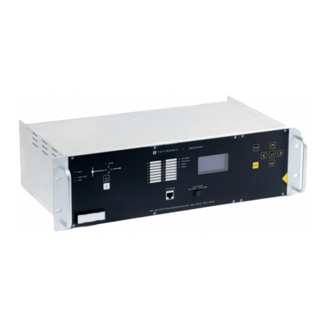
Thytronic
Thytronic DMC3S User manual
Thytronic
Thytronic NV10P User manual
Thytronic
Thytronic NVA100X User manual

Thytronic
Thytronic SSG User manual
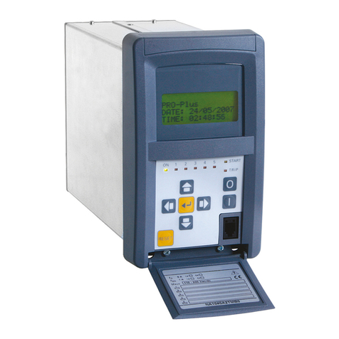
Thytronic
Thytronic NA30 User manual

Thytronic
Thytronic NC020 User manual
