Entes MK-05 User manual

MOTOR (FAZ) KORUMA RÖLELERÝ
MK-05 / 05P / 06 / 06P, MKC-05 / 05P / 06 / 06P
Boyutlar
Teknik Bilgi
Ýþletme Gerilim (Un) :220 VAC (MK-05/05P, MKC-05/05P)
3 faz ve nötr, yýldýz ba¤lantý
120 VAC (MKC-05/05P Özel dizayn)
3 faz ve nötr, yýldýz ba¤lantý
380 VAC (MK-06/06P, MKC-06/06P)
3 faz, üçgen ba¤lantý
440 VAC (MKC-06/06P Özel dizayn)
3 faz, üçgen ba¤lantý
220 VAC (MKC-06/06P Özel dizayn)
3 faz, üçgen ba¤lantý
Koruma rölesinin iþletme gerilimi korunan þebekeden sa¤lanýr.
Ýþletme Aralý¤ý : ( 0.9-1.1 ) x Un
Ýþletme Frekansý : 50/60 Hz
Kontak Tipi : 1 Enversör, 8A, 2000 VA, Cosj=1
Gecikme Zamaný : 0.1-10 sn ( Ayarlanabilir)
Asimetri Aralý¤ý : %5- %15 ; 3x380V (3x415V)
Faz Sýrasý Korumasý : Var
Ortam Sýcaklý¤ý : -5 oC ; + 50 oC
Koruma Sýnýfý : IP 20
Boyutlar : Tip PK 21 (MK-05/05P ve MK-06/06P için)
Tip PK 25 (MKC-05/05P ve MKC-06/06P için)
Ba¤lantý Þekli : Pano içine dikey veya klemens rayýna
A¤ýrlýk : 0.3 kg (MK-05/05P/06/06P için)
0.2 kg (MKC-05/05P/06/06P için)
1. Güç LEDi ; Besleme gerilimi varsa yanar.
2. Röle LEDi ; Röle çekili oldu¤unda yanar.
3. Faz Sýrasý Ýkaz LEDi; Ters faz durumunda
yanar.
4. Asimetri Hata Ýkaz LEDi; Ayarlanan
asimetri de¤eri aþýldý¤ýnda yanar.
(3 ve 4 nolu LEDler faz hatasý
durumunda ayný anda yanar.)
5. (3) Nolu kontak normalde açýk
6. (2) Nolu kontak ortak
7. (1) Nolu kontak normalde kapalý
8. Zaman gecikmesi ayar potu
(0.1sn-10sn)
9. Asimetri ayar potu(%5-%15)
10. L1, L2, L3. faz konnektörü
11. Nötr konnektörü
(Yalnýzca 05 ve 05P serisi için)
12. PTC ba¤lantýsý
(Sadece P modellerinde)
*(MK-05P, MK-06P, MKC-05P ve
MKC-06P tip röle ile
PTC kullanýlmadý¤ýnda PTC
konnektörleri kýsa devre edilmelidir.)
Fonksiyon Diyagramý
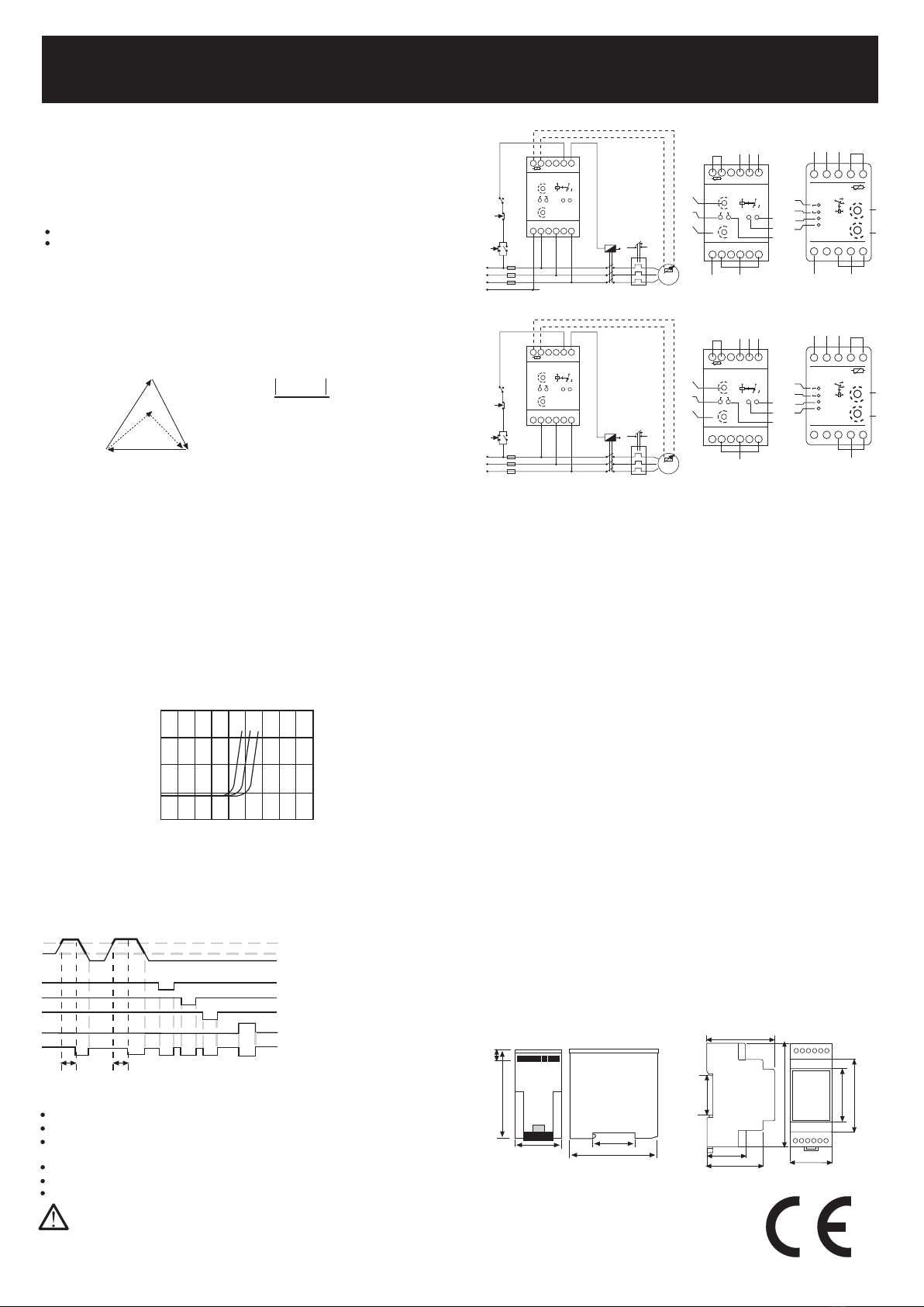
Ba¤lantý Þemalarý
Güvenli Kullaným ve Kurulum Ýçin Uyarýlar
Aþaðýdaki talimatlara uyulmamasý halinde yaralanma veya ölümle sonuçlanabilecek
durumlar ortaya çýkabilir.
Cihaz üzerindeki herhangi bir iþlemden önce tüm besleme gerilimlerini kesiniz.
Cihaz þebekeye baðlý iken ön paneli çýkarmayýnýz.
Cihazý solvent veya benzeri maddelerle temizlemeyiniz. Cihazý temizlemek için
sadece kuru bez kullanýnýz.
Cihazý çalýþtýrmadan önce baðlantýlarýnýn doðru olduðunu kontrol ediniz.
Cihazý panoya monte ediniz.
Cihazýnýzdaki herhangi bir sorunda yetkili satýcýnýzla temas kurunuz.
A2910 / Rev.8
Genel
Sanayi tesislerimizde yaygýn olarak kullanýlan elektrik motorlarýnýn iki faza kalarak
aþýrý ýsýnmasý ve yanmasý sýkça karþýlaþýlan arýza kaynaklarýndan biridir. Motor
korumasýnda sýkça kullanýlan termik manyetik röle gerek elektromekanik yapýsý,
gerekse demeraj akýmýnýn karþýlanabilmesi için akým ayarýnýn yüksek tutulmasý
nedeniyle, koruma iþleminde yetersiz kalmaktadýr.
Bu olumsuz etkileri ortadan kaldýracak þekilde tasarlanmýþ bulunan MK-05,
MKC-05, MKC-06, MK-06 Motor Koruma Röleleri aþa¤ýdaki koruma fonksiyonlarýný
yerine getirir:
4- Yetersiz Besleme Voltajý
PK21 kutusunda MK-05 ile MK-05P cihazlarýnda L1 fazý, MKC-05 ile
MKC-05P cihazlarýnda L3 fazý besleme fazýdýr. Besleme fazý cihazýn iþletme geriliminin
PK21 kutusunda MKlar ve MKCler için %60-65in altýna düþtü¤ü zaman röle
gecikmesiz açma yapar ve hata LEDleri sýrayla yanýp sönmeye baþlar.
2- Faz sýrasý
Faz sýrasýnýn ters oldu¤u durumlarda (L1, L2, L3 saat yönünde de¤il) motor devreye
alýnmaz. Herhangi bir nedenle faz sýrasý bozulursa motor gecikmesiz devreden
çýkarýlýr. Cihazýn rölesi býrakýr, Röle LEDi söner, faz sýrasý hatasý ikaz LEDi yanar.
100k
10k
1k
100
10
20 40 60 80 100 120 140160 180 200
Sýcaklýk (0C)
R(W)
3- PTC korumasý (sadece MK-05P, MKC-05P, MKC-06P ve MK-06P
tipinde)
Motor sargý sýcaklý¤ý PTCnin sýcaklýk sýnýr de¤erini aþarsa motor geçikmesiz olarak
devreden çýkartýlýr. Cihazýn rölesi býrakýr, Röle LEDi söner.
Bu özellik sadece MK-05P, MKC-05P ve MK-06P, MKC-06Pde yer almaktadýr.
De¤iþik sýcaklýk sýnýr de¤erlerine (110 oC, 120 oC, 130 oC ) sahip üç PTCnin direnç
- sýcaklýk de¤iþimleri aþa¤ýdaki þekilde verilmektedir.
VRef
VRef = 380 VAC
x 100
Asimetri % = -
VL12
VL31
VL31 VL12
VL23
VL31 VL12
Gerilim dengesizli¤i motor sargý sýcaklý¤ýnýn belli bir miktar artmasýna ve dolayýsýyla
motor gücünün düþmesine neden olur.
Asimetri sýnýr de¤erleri kullanýcý tarafýndan %5 ile %15 arasýnda ayarlanabilir. Histerisis
%20 dir.
Örnek : 3 x 380 Vluk þebekede %10 asimetri varsa tek fazdaki açma de¤eri
380-( 380 x %10 )= 342 V olarak hesaplanýr. Böylece devreye alma de¤eri :
342 + ( 342 x 10% x %20 )= 348.8 V olacaktýr.
1- Gerilim Dengesizli¤i (Ayarlanabilir)
Üç fazlý sistemlerde gerilim dengesizliði (asimetri);
Yüklerin fazlara dengesiz baðlanmasý sonucu oluþabileceði gibi,
Üç fazlý motorlarda fazlardan birinin kesilmesi durumunda da oluþur. Bu durumda
kesilen faza ait motor sargý ucunda, motorun diðer sargýlarý üzerinden indüklenerek
dönen gerilim görülür. Bu gerilim deðeri motorun cinsine ve yük durumuna göre
deðiþir.
Faz yokluðu veya herhangi bir sebepten oluþabilecek faz-faz arasý gerilim
dengesizliði kullanýcýnýn ayarladýðý asimetri deðerinden küçükse çýkýþ rölesi çekilidir.
Eðer gerilim dengesizliði ayarlanan asimetri deðerini (%5-15) aþarsa; çýkýþ rölesi
ayarlanan zaman gecikmesi (0,1-10sn.) sonunda býrakýr ve motor devre dýþý kalýr.
Cihazýn rölesi býrakýr, röle LEDi söner, Asimetri Hatasý ikaz LEDi yanar. Eðer gerilim
dengesizliði zaman gecikmesi bitmeden ayarlanan deðerin altýna inerse çýkýþ rölesi
çekili kalýr ve motor devreden çýkartýlmaz.
Uygulamalarýnýzda; motorun iki faza kalmasý esnasýnda motorun diðer sargýlarýndan
indüklenen gerilim deðerini de göz önünde bulundurarak cihaz üzerinden uygun
asimetri deðerini ayarlayýnýz.
TÝP PK21
35
80
44
80 14
TÝP PK25
35 mm
90 mm
45 mm
62 mm
58 mm
32 mm
48 mm
35 mm
*
C1
T1
Stop
T1
N
M
3 ~
PTC
Start
L1
L2
L3
N
C1
321
N L1 L2 L3
PTC
*
C1
T1
Stop
T1
M
3 ~
PTC
Start
L1
L2
L3
C1
321
L1 L2 L3
1
2
3
PTC
321
L1 L2 L3
1
2
3
PTC
56712
9
3
8
2
1
4
10
*
321
N L1 L2 L3
PTC
56712
9
3
8
2
1
4
11 10
*
*
5 6 7 12
1
2
3
4
11 10
8
9
3 2 1
1
3
2
N L1 L2 L3
10
15
10
5
0.1
4
6
8
PTC
MK-05/05P
Phase Failure
Device
t(sec.)
%
Asym.
Phs. Seq.
Asym.
Output
On
Phs.
Fail
*
5 6 7 12
1
2
3
4
10
8
9
3 2 1
1
3
2
L1 L2 L3
10
15
10
5
0.1
4
6
8
PTC
MK-06/06P
Phase Failure
Device
t(sec.)
%
Asym.
Phs. Seq.
Asym.
Output
On
Phs.
Fail
1
2
3
1
2
3
Yukarýdaki önlemlerin uygulanmamasý sonucu doðabilecek istenmeyen
durumlardan üretici firma hiç bir þekilde sorumlu tutulamaz.
Ayarlanan Asimetri
Histerisis
L1
L2
L3
Çýkýþ Rölesi
TD= Zaman Gecikmesi
TD
TD
Yanlýþ Faz Sýrasý
N
Bu ürün, 30.05.2008 tarih ve 26891 sayýlý resmi gazetede yayýnlanan
EEE Yönetmeliðinin Madde 2 ve Ek-1A madde 9 kapsamýndadýr.
Asm.
Phs.
Seq.
Phs.
Fail.
OutOn
MKC-06/06P
5
15
10
%
Asm.
10
8
6
4
20.1
t(s)
Asm.
Phs.
Seq.
Phs.
Fail.
OutOn
MKC-05/05P
5
15
10
%
Asm.
10
8
6
4
20.1
t(s)
Asm.
Phs.
Seq.
Phs.
Fail.
OutOn
MKC-06/06P
5
15
10
%
Asm.
10
8
6
4
20.1
t(s)
Asm.
Phs.
Seq.
Phs.
Fail.
OutOn
MKC-05/05P
5
15
10
%
Asm.
10
8
6
4
20.1
t(s)
Dimensions
100k
10k
1k
100
10
20 40 60 80 100 120 140160 180 200
Temperature (0C)
R(W)
VRef
VRef = 380 VAC
x 100
Asymmetry % = -
VL12
VL31
VL31 VL12
VL23
VL31 VL12
Function Diagram
PHASE FAILURE DEVICES
MK-05 / 05P / 06 / 06P, MKC-05 / 05P / 06 / 06P
1. On LED
2. Out LED
3. Phase sequence fault LED
4. Asymmetry fault LED
(While LED no. 3 and 4 are ON at the
same time, it means there is phase
failure)
5. Contact ( 3 ) NO connection of output relay
6. Contact (2 ) common connection of
output relay
7. Contact (1) NC connection of output relay
8. Time adjusment (0.1 sec.-10 sec.)
9. Asymmetry adjusment (5%-15%)
10. L1, L2, L3 phase connection
11. Neutral connection
(Only for 05 and 05P series)
12. PTC connection*
*: Only available in MK-05P,MKC-05P If
PTC is not used in MK-06P, MKC-06P by
any reason, the PTC terminals should be
short circuited.
Connection Diagrams
General
One of the common faults faced in industrial plants is overheating and damaging
of 3 phase motors due to the phase failure. Thermic-magnetic device which is an
essential element in motor protection is generally too slow due to both its
electromechanical structure and the use of hing current setting range to assure
demarrage without tripping. Being designed to eliminate the above disadvantages,
MK-05, MKC-05, MKC-06 and MK-06 Phase Failure Devices serve the following
protection features
Technical Data
Rated Voltage (Un) : 220 VAC (For MK-05/05P, MKC-05/05P)
3 phase + neutral, 4 wires connection
120 VAC (MKC-05/05P Custom design)
3 phase + neutral, 4 wires connection
380 VAC (For MK-06/06P, MKC-06/06P)
3 phase, 3 wires connection
440 VAC (MKC-06/06P Special design)
3 phase, 3 wires connection
220 VAC (MKC-06/06P Special design)
3 phase, 3 wires connection
The three phase network being protected is used as the device power
supply.
Operating Range : (0.9-1.1) x Un
Rated Frequency : 50/60 Hz
Output Contacts :1 C/O with 8A, 2000 VA, Cosj=1
Asymmetry Range : 5% - 15%; 3 x 380 VAC
Tripping Time : 0.1 - 10 sec. (adjustable)
Phase Sequence : Available
Ambient Temperature : -5 oC to + 50 oC
Protection Class : IP 20
Diemensions : Type PK 21 (For MK-05/05P, MK-06/06P)
Type PK 25 (For MKC-05/05P, MKC-06/06P)
Installation : Surface mounting or on the mounting rails
Weight : 0.3 kg (For MK-05/05P, MK-06/06P)
0.2 kg (For MKC-05/05P/06/06P)
Precautions For Installation and Safe Use
Failure to follow those instructions will result in death or serious injury.
Disconnect all power before working on equipment.
When the device is connected to the network, do not remove the front panel.
Do not try to clean the device with solvent or the like. Only clean the device
with a dried cloth.
Verify correct terminal connections when wiring.
Electrical equipment should be serviced only by your compedent seller.
Mount device to the panel.
A2910 / Rev.8
1. Voltage Unbalance (Adjustable)
Unbalanced voltage may occured when;
The mains are loaded with unbalanced distribution,
One of the 3-phase of motor has lost. In this case, some amount of voltage which
produced by other phases will be inducted on the lost phase. Amount of this value
depends on both the motor type and amount of load.
Output relay is activated when a phase has lost or an unbalanced Phase-Phase
voltage value, which is occured with any reason, is smaller than the user defined
asymetrical value. If this unbalanced voltage value exceeds the adjusted asymetrical
value (5-15%); output relay will release itself and switches off the motor at the end
of adjusted time delay (0.1-10 sec.); Relays LED is turned off. Asymetry error LED
is turned ON. If the fault has gone within the delay time, the output relay is remoined
and will not switch off the motor.
In Applications; a proper asymetrical value should be adjusted regarding to the
inducted voltage value in two-phase which are remained after the other one has
lost.
The voltage asymmetry causes the rise in motor temperature and a reduction of
the rated motor power.
Voltage asymmetry limit values are adjusted (5%-15%) by the user.
Hysteresis is fixed at 20%.
Example: Given 3x380 V supply with 10% asymmetry,
Relay switches OFF at: 380-(380 x10%)=342 V
Relay switches ON at: 342 + (342 x 10% x 20%)=348.8 V
2. Phase Sequence
When the phase sequence is correct (L1, L2, L3 in clockwise direction) the output
relay is activated; however, if the sequence is changed by any reason, the output
relay switches OFF immediately. Relay LED is OFF, Phase Sequence error LED is
ON.
3.PTC Protection (Only Available in MK-05P, MKC-05P,
MKC-06P & MK-06P versions)
When the coil temperature in motors exceeds Tc, the limit temperature of PTC, the
output relay switches off immediately, Relay LED is OFF. This feature is included
only in MK-05P,MKC-05P,MK-06P and MKC-06P. See following figure for typical
resistance of PTC vs temperature characteristics for three different swiching
temperatures (110 oC, 120 oC, 130 oC). Normally, PT-110 is used and it can be
changed upon request.
5. Insufficient Supply
L1 is the supply phase of the MK-05 and MK-05P in PK21 package while L3 is the
suply phase of MKC-05 and MKC-05P devices. For MK and MKC devices if supply
voltage falls below 60-65% of rated voltage, output relay switches off without delay
and error leds start to blink one after another sequentially.
TYPE PK21
35
80
44
80 14
35 mm
90 mm
45 mm
62 mm
58 mm
32 mm
48 mm
35 mm
TYPE PK25
*
C1
T1
Stop
T1
N
M
3 ~
PTC
Start
L1
L2
L3
N
C1
321
N L1 L2 L3
PTC
*
C1
T1
Stop
T1
M
3 ~
PTC
Start
L1
L2
L3
C1
321
L1 L2 L3
1
2
3
PTC
321
L1 L2 L3
1
2
3
PTC
56712
9
3
8
2
1
4
10
*
321
N L1 L2 L3
PTC
56712
9
3
8
2
1
4
11 10
*
*
5 6 7 12
1
2
3
4
11 10
8
9
3 2 1
1
3
2
N L1 L2 L3
10
15
10
5
0.1
4
6
8
PTC
MK-05/05P
Phase Failure
Device
t(sec.)
%
Asym.
Phs. Seq.
Asym.
Output
On
Phs.
Fail
*
5 6 7 12
1
2
3
4
10
8
9
3 2 1
1
3
2
L1 L2 L3
10
15
10
5
0.1
4
6
8
PTC
MK-06/06P
Phase Failure
Device
t(sec.)
%
Asym.
Phs. Seq.
Asym.
Output
On
Phs.
Fail
1
2
3
1
2
3
Asm.
Phs.
Seq.
Phs.
Fail.
OutOn
MKC-06/06P
5
15
10
%
Asm.
10
8
6
4
20.1
t(s)
Asm.
Phs.
Seq.
Phs.
Fail.
OutOn
MKC-05/05P
5
15
10
%
Asm.
10
8
6
4
20.1
t(s)
Asm.
Phs.
Seq.
Phs.
Fail.
OutOn
MKC-06/06P
5
15
10
%
Asm.
10
8
6
4
20.1
t(s)
Asm.
Phs.
Seq.
Phs.
Fail.
OutOn
MKC-05/05P
5
15
10
%
Asm.
10
8
6
4
20.1
t(s)
No responsibility is assured by the manufacturer or any of its subsidiaries
for any consequences arising out of the use of this material.
Adjusted unbalance value
Hysterisis
L1
L2
L3
Output Relay
TD= Tripping Time
TD
TD
Wrong phase sequence
N
This manual suits for next models
7
Table of contents
Languages:
Other Entes Relay manuals


