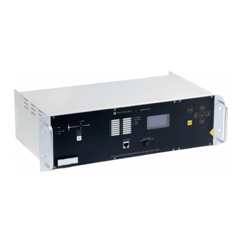
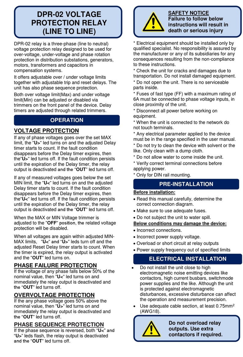
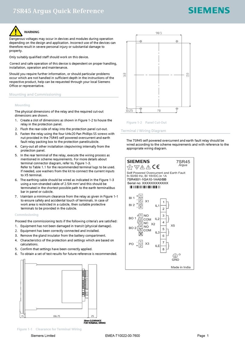
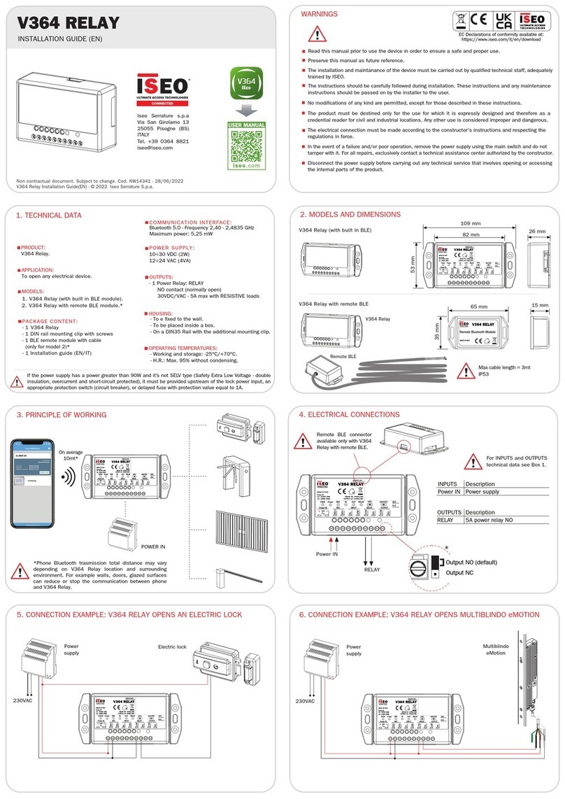
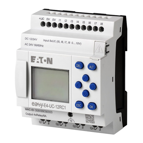
Thytronic SSG User manual

SSG
1
SSG000\08
12-2005
SSG
Relè di protezione a microprocessore di massima corrente e di terra con
funzioni direzionali di massima corrente e di terra
Conforme a Specifica Enel DK5600
Microprocessor-based relay for overcurrent and earth fault protection with
directional functions of overcurrent and earth fault
Suitable to Enel DK5600 requirements
MANUALED'ISTRUZIONE
INSTRUCTIONMANUAL
27-50-51-59T-67-50N-51N-59N-67N

SSG000\08
12-2005
2
0 - INDICE
1 - GENERALITÀ
2 - DESCRIZIONE
3 - CARATTERISTICHE TECNICHE
4 - CARATTER
ISTICHE
DI FUNZIONAMENTO
5 - PRINCIPIO DI FUNZIONAMENTO
6 - INSTALLAZIONE
7 - TARATURA E MESSA IN SERVIZIO
8 - PROCEDURE DI PROVA
9 - MANUTENZIONE
10 - MAGAZZINAGGIO
0 - CONTENTS
1 - GENERAL
2 - DESCRIPTION
3 - TECHNICAL DATA
4 - FUNCTION CHARACTERISTICS
5 - FUNCTION PRINCIPLE
6 - INSTALLATION
7 - SETTING AND COMMISSIONING
8 - TESTING PROCEDURES
9 - MAINTENANCE
10 - STORAGE
3
4
6
10
30
36
51
78
96
96

SSG
3
SSG000\08
12-2005
1 - GENERAL
The relay type SSG is intended for the protection against overloads,
short circuits and earth faults in radial network, ring mains or variable
structurenetworks.
The relay features three input measuring circuits for the line
currents, a three-phase circuit to measure the line voltages and
two circuits, provided with a band pass filter, to measure the
residual current and the residual voltage.
Versions withundervoltage(27)andvoltagemonitoring(59T)
functions are available, the undervoltage information may be
useful for load (transformers) shedding schemes.
Therelayprovidesforthefollowing protection functions, each
one with its own delay:
-undervoltage(27) withoneoperationthresholdwithdefinitetime;
-overcurrentnondirectionalprotection(50-51)withthreeoperation
thresholds, the first one with independent or dependent time
and the other two with independent time;
-linevoltagemonitoringfunction(59T)withoneoperationthreshold
with definite time;
- overcurrent directional protection (67) with three operation
thresholds, the first one with independent or dependent time
and the other two with independent time;
-residualcurrentnondirectional protection (50N-51N)withthree
operationthresholds,thefirstonewithindependentordependent
time and the other two with independent time;
-residualvoltageprotection(59N)with two operation thresholds,
both with independent time;
- earth fault directional protection (67N) with three operation
thresholds, the first one with independent or dependent time
and the other two with independent time;
-breakerfailureprotection (BF)programmableforevery threshold
on all protection functions.
The setting values and the types of curve are completely
programmable by the user, as well as the assignment of the final
relays and their working mode.
The digital display on the front panel shows the following
informations:
- setting values and operating mode;
- actual values of input quantities;
- number of operations performed for each one of the protection
functions;
-countingofthe cumulativeswitchedcurrentsforeach pole ofthe
circuit breaker;
-valuesofinputquantitiescorrespondingtothelasteightoperations
(start and trips).
The blocking circuit enables to perform selective protection
systems, according to the accelerated protection scheme.
Aversionisavailablewithdigitalinputcircuits,whichenables
toperformadaptive protection systems.
Thankstotheserial communication circuit,allthereadand set
operations can be executed by a remote control unit.
The microprocessor-based technology enables a continuous
monitoring of the internal circuits, to ensure the correct working
of the relay.
1 - GENERALITÀ
IlrelètipoSSGprovvede alla protezionecontroisovraccarichi,
i corti circuiti e i guasti verso terra nelle reti radiali, ad anello o
a configurazione variabile.
Essocomprendetrecircuiti dimisuraperle trecorrentidilinea,
uncircuitotrifaseper lamisuradelletensionidi lineaeduecircuiti,
dotati di filtro passa banda, per la misura della corrente residua
e della tensione residua.
Sonodisponibili versioni con funzioni di minimatensione(27)
e presenza tensione (59T) che possono essere utilizzate per il
distacco e la rialimentazione sequenziale dei trasformatori.
Il relè esegue le seguenti funzioni di protezione, ciascuna
dotata del proprio ritardo:
- protezione di minima tensione (27) con una soglia d'intervento
programmabile a tempo indipendente;
- protezione non direzionale di massima corrente (50-51) con tre
soglied'intervento,laprima program-mabileatempoindipen-
dente o dipendente e le rimanenti a tempo indipendente;
-protezionedi presenzatensione(59T)con unasogliad'intervento
programmabile a tempo indipendente;
- protezione direzionale di massima corrente (67) con tre soglie
d'intervento,laprimaprogrammabileatempoindipendente o
dipendente e le rimanenti a tempo indipendente;
- protezione non direzionale di massima corrente residua (50N-
51N) con tre soglie d'intervento, la prima programmabile a
tempo indipendente o dipendente e le rimanenti a tempo
indipendente;
- protezione di massima tensione residua (59N) con due soglie
d'intervento programmabili a tempo indipendente;
- protezione direzionale di terra (67N) con tre soglie d'intervento,
laprimaprogrammabileatempoindipendente o dipendente e
le rimanenti a tempo indipendente.
-protezionepermancataaperturainterruttore(BF) programabile
per ogni soglia su tutte le funzioni di protezione.
I valori di taratura e i tipi di curva d'intervento sono comple-
tamente programmabili dall'utente, così come l'assegnazione e
il modo di funzionamento dei relè finali.
L'indicatorealfanumericopostosulpannellofrontale permet-
te di rilevare:
- valori dei parametri di taratura e modo di funzionamento;
- valori istantanei delle grandezze d'entrata;
- numero d'interventi eseguiti per ciascuna funzione di protezio-
ne;
- conteggio della corrente comulativa interrotta da ogni polo
dell'interruttore;
- valori delle grandezze d'entrata corrispondenti agli ultimi otto
interventi (avviamenti e interventi).
Ilcircuitodibloccopermette di realizzaresistemidiprotezione
selettiva a logica accelerata.
La versione dotata dei circuiti d'entrata digitali permette di
realizzare sistemi di protezione adattativi.
Grazie al collegamento di comunicazione seriale, tutte le
operazioni di lettura e di taratura possono essere eseguite a
distanza da parte di un'unità centrale di controllo.
La tecnologia costruttiva a microprocessore assicura inoltre
un controllo permanente autodiagnostico del corretto funziona-
mento interno del relè.

SSG000\08
12-2005
4
2 - DESCRIZIONE
Le caratteristiche costruttive più significative del relè di
protezione tipo SSG sono:
- morsetti largamente dimensionati, con attacco a vite;
-costruzioneditipoestraibile, conconnettoreaventeicontatti
argentati a 6 punti di contatto;
- dispositivi cortocircuitanti nei circuiti amperometrici;
- involucro completamente isolante e protetto contro la pol-
vere e lo stillicidio;
- pannello frontale del tipo a membrana, completamente
protetto contro le scariche elettrostatiche.
Le caratteristiche circuitali più significative sono:
- programmazione delle caratteristiche di funzionamento
completamente digitale mediante i tasti del pannello frontale e
visualizzazione mediante l'indicatore LCD a 16 caratteri, dotato
d'illuminazione interna;
-assenzadiqualsiasidispositivodi taratura di tipo meccanico
tradizionale, in quanto tutti i coefficienti di taratura sono conser-
vati nella memoria non volatile del microprocessore;
-circuitid'entrataed'uscita isolati galvanicamente(compresi
i circuiti di comunicazione, di blocco e d'entrata digitale);
-controllopermanentedell'azzeramentodeicircuiti analogici
d'entrata e compensazione automatica dell'eventuale deriva;
- misura dei segnali d'entrata mediante campionamento e
conversione A/D alla frequenza di 1 kHz;
- filtraggio ottimale dei segnali d'entrata mediante l'utilizzo
congiunto di filtri analogici e digitali;
- contatti finali d'uscita di tipo elettromeccanico tradizionale,
concontrollopermanentedellacontinuitàdelle bobine di coman-
do;
- orologio - calendario con circuiti di memoria che garanti-
sconoilfunzionamentosenzaalimentazionesinoa150ore(RTC,
Real Time Clock);
- alimentazione ausiliaria realizzata mediante un circuito
stabilizzatore a commutazione, avente un campo d'impiego par-
ticolarmente ampio e una dissipazione di potenza molto ridotta.
Le caratteristiche di funzionamento più significative sono:
- programmazione dei modie deiparametridifunzionamento
mediante i tasti frontali e l'indicatore alfanumerico, con una
procedura basata sull'attuazione di scelte guidate e sull'indica-
zione esplicita e immediata delle operazioni eseguite;
- necessità della conferma finale (ovvero dell'annullamento)
per ogni modifica delle caratteristiche di funzionamento;
- le operazioni di modifica delle caratteristiche non interrom-
pono il normale funzionamento del relè;
-oltreaivalorideiparametri (soglie e tempid'intervento)sono
completamenteprogrammabilianchelemodalitàdiassegnazio-
ne delle varie funzioni di protezione ai relè finali, la condizione
normale di ogni relè finale e il tipo di ripristino;
- impossibilità di programmare valori dei parametri inaccet-
tabili, grazie alla limitazione automatica d'inizio e fondo scala dei
rispettivi campi di taratura;
- duplicazione dellamemoria contenente idati di taratura,con
correzione automatica di eventuali errori.
Il relè SSG è dotato di interfaccia standard RS485 per il
collegamentoconl'unitàcentrale di supervisionetramiteunarete
di comunicazione; è disponibile a richiesta una interfaccia locale
2 - DESCRIPTION
ThemostsignificantconstructivefeaturesoftheSSGprotection
relay are:
- well oversized screw-type terminals;
- extractable-type construction, with connector having silver
plated contacts with 6 contact points;
- current measuring circuits provided with short-circuiting
devices;
- fully insulating shell protected against dust and dripping;
- membrane front panel, fully protected against electrostatic
discharges.
The most significant circuitry features are:
- full digital programming of operating features by means of
front panel keys and 16-digit LCD indicator with back lighting;
- absence of any traditional mechanical calibrating device,
since all calibration coefficients are stored in the microprocessor
non-volatile memory;
- galvanically insulated input and output circuits
(communication, blocking and digital input circuits included);
- continuous monitoring of analog input circuit off-set and
automatic compensation of possible drift;
- measurement of input signals through sampling and A/D
conversion at a rate of 1 kHz;
- optimum filtering of input signals through combined use of
analog and digital filters;
-traditionalelectromechanical-typefinal output contactswith
continuous monitoring of control coil continuity;
- Real Time Clock circuits with power supply backup,
theoperationisguaranteewithloss of power supply upto
150hours;
- auxiliary supply comprising a switching-type voltage
stabilizing circuit having a very wide working range and a very
small power dissipation.
The most significant operating features are:
-programmingofoperatingmodesand parameters by means
of the front keys and alphanumeric display, with a programming
procedurebasedoncarryingout guided selectionsandonexplicit
and immediate signalling of the operations being performed, so
that such procedure can be carried out without coding tables or
mnemonicinformations;
- final confirmation (otherwise cancelling) required for any
change in the operating features;
- the feature modification operations do not interrupt the
normal functions of the relay;
- in addition to the parameters values (trip level and operating
times), the modalities for allocation of the various protection
functionstothe finalrelays,thenormalstatusofthe eachfinalrelay
and the kind of reset are also fully programmable;
-impossibilityofprogrammingunacceptable parametervalues,
thanks to the automatic limitation of top and bottom scale values
for the relative setting ranges;
- doubling of the memory containing the setting information,
and automatic correction of any possible error.
The SSG relay is provided of standard RS485 interface for

SSG
5
SSG000\08
12-2005
con un PC portatile mediante il connettore frontale a fibra ottica.
Il protocollo di comunicazione può essere scelto tra due tipi:
-MODBUSRTU®conparametri programmabili (velocità,
parità, stop - bit),
-protocolloTHYTRONICproprietarioin modo da garantire
la compatibilità con le reti di comunicazione che prevedono
l'impiego del dispositivo concentratore SCR.
Ladisponibilitàdiun protocollo standardconsentediintegrare
i relè di protezione SSG in un sistema di supervisione (SCADA)
standard;perleinformazioni relative allacomunicazione(drivers,
indirizzidimemoria,istruzioni edesempi)occorrefareriferimento
al Manuale per la programmazione remota.
La funzione direzionale di corrente utilizza un criterio parti-
colare di funzionamento basato su un algoritmo ad aggancio di
fase: ciò permette al relè di funzionare correttamente anche in
occasione di un guasto franco trifase in cui la tensione della linea
si riduce notevolmente sino ad annullarsi.
Il circuito di blocco, destinato alla realizzazione di sistemi di
protezione a logica accelerata, è dotato anch'esso di elevate
caratteristiche di affidabilità, grazie al processo di controllo
periodico della continuità del collegamento a filo pilota.
I circuiti d'entrata digitale, destinati tipicamente alla realizza-
zionedisistemidi protezioneadattativi,permettonodi selezionare
due differenti configurazioni di taratura.
Inalternativapossonoessereutilizzati per le seguentifunzioni
accessorie:
- ripristino a distanza,
- comando memorizzazione misure,
- ingresso di blocco da contatto,
- supervisione del circuito di scatto (TCS),
- comando di sincronizzazione orologio (mediante collega-
mento dati al sistema di supervisione).
Sono presenti le funzioni accessorie:
- memoria dei valori delle grandezze d'entrata corrispondenti
agliultimiottointerventi (TRIP)eregistrazionedeisegnali misurati
peruntempoprecedenteesuccessivo all'intervento (2.5 +2.5s);
- supervisione del circuito di scatto (TCS);
- protezione per mancata apertura interruttore (BF);
- inibizione delle funzioni programmabile all'accensione per
un tempo regolabile.
connection with the central supervisor unit; it is available upon
request a local interface with a portable PC by means of the fiber
optic front panel connector.
The communication protocol can be selected from two types:
- MODBUS RTU® with programmable parameters (rate,
parity, stop - bit),
-THYTRONICprotocoltoguarantee the compatibility with
communication network including SCR concentrators.
The availability of a standard protocol allow the protection
relay SSG integration in the supervisor system (SCADA); for
information about communication (drivers, memory map,
instructionsandexamples)pleaserefertotheRemoteprogramming
manual.
The overcurrent directional function makes use of a special
criteriumbasedona phaselockloopalgorithm:this featureallows
therelayto correctlyoperateinthe presenceofasolid three-phase
short circuit close to the measuring point, where the line voltage
drops to zero.
The blocking circuit, which is intended to build up protection
systems according to the acceleration scheme, presents as well
high reliability characteristics, thanks to a periodic monitoring
process for the continuity of the pilot wire connection.
The digital input circuits, wich are typically intended to build
upanadaptiveprotection system,enablestoselectany one oftwo
differentsettingconfigurations.
Otherwise they can feature the following ancillary functions:
- remote reset control,
- trigger for measures saving,
- input block signal from contact,
- trip circuit supervision (TCS),
- syncronizing input for Real Time Clock (by means of data
transmissionwithsupervisorsystem).
Other functions are present:
-storingthevalues ofinputquantitiescorresponding tothelast
fouroperation(TRIP)andtracememorywithpreandposttrigger;
- trip circuit supervision (TCS);
- circuit breaker failure function (BF);
-programmablefunctionsinhibitiontothelightingforadjustable
delay.

SSG000\08
12-2005
6
3 - CARATTERISTICHE TECNICHE
Alimentazione ausiliaria
tensione:
- valore (campo) nominale
- campo d'impiego (per ciascuno dei valori nominali
sopra indicati)
frequenza
(per alimentazione con tensione alternata)
fattore di distorsione massimo (per alimentazione con
tensione alternata)
componente alternata massima (per alimentazione con
tensione continua):
- sinusoidale raddrizzata
- sinusoidale
durata massima interruzione
tempo massimo d'entrata a regime
potenzaassorbitamassima
Circuiti d'entrata amperometrici di fase
corrente nominale
sovraccarico permanente
sovraccarico termico (1 s)
frequenza:
- valore di riferimento
- campo nominale d'impiego
potenzaassorbita
caratteristiche consigliate per i trasformatori di corren-
te
(2)
:
- per valori di corrente fino a 10
I
N
- per valori di corrente fino a 20
I
N
Circuiti d'entrata voltmetrici
tensione nominale di riferimento
sovraccarico permanente
frequenza:
- valore di riferimento
- campo nominale d'impiego
campo di misura
potenzaassorbita
caratteristicheconsigliateperitrasformatoridi tensione
3 - TECHNICAL DATA
Auxiliary supply
voltage:
- nominal value (range)
-operativerange(foreachoneoftheabovementioned
nominal values)
frequency (for alternating voltage supply)
maximum distorsion factor ( for alternating voltage
supply)
maximumalternatingcomponent(fordirectvoltage
supply):
- full wave rectified sine wave
- sine wave
maximuminterruptiontime
maximumset-uptime
maximumpowerconsumption
Phase current input circuits
nominal current
permanent overload
thermal overload (1 s)
frequency:
- reference value
- operative nominal range
ratedconsumption
suggested characteristics for current transform-
ers
(2)
:
- for current values up to 10
I
N
- for current values up to 20
I
N
Voltage input circuits
nominal reference voltage
permanent overload
frequency:
- reference value
- operative nominal range
effective range
ratedconsumption
suggested characteristics for voltage transformers
24...125V
110...230V
110...250V
18...150V
88...265V
88...300V
45...66Hz
15 %
(1)
100 %
(1)
80 %
(1)
20ms
800ms
10 W (15 VA)
I
N
1 A
5 A
4
I
N
100
I
N
f
N
50 Hz
60 Hz
0.95...1.05
f
N
0.5VA(5A)-0.03VA(1A)
5 VA - 5P10
5 VA - 5P20
U
R
100V
2
U
R
f
N
50 Hz
60 Hz
0.95...1.05
f
N
0.05...2
U
R
0.5 VA
10VA - cl 1 - 3P
NOTA1-Ilvaloremassimodipiccodellatensioneausiliarianondevesuperare
215o390Vperciascunodeiduecampinominaliindicati.
NOTA2-Laprestazionenominalepuòvariareinfunzionedeicarichiapplicatiai
TA,comprensividella resistenzadeiconduttori.
NOTE1 -The maximumpeakvalue ofthe auxiliaryvoltage mustnotbe
higherthan215o390Vrespictivelyforeachoneoftheabovementioned
nominalranges.
NOTE2-Theratedburdencanvarydependingontheloadsconnectedtothe
CT's,includingtheresistanceoftheconductors.

SSG
7
SSG000\08
12-2005
I
EN
1 A
5 A
5
I
EN
100
I
EN
f
N
50 Hz
60 Hz
0.95...1.05
f
N
25 dB
0.5VA(5A)-0.03VA(1A)
5 VA - 5P10
5 VA - 5P20
U
R
100 V
2
U
R
f
N
50 Hz
60 Hz
0.95...1.05
f
N
25 dB
0.5 VA
10 VA - cl 1 - 3P
0.05...0.8
U
R
Circuito d'entrata di corrente residua
corrente nominale secondaria
sovraccarico permanente
sovraccarico termico (1 s)
frequenza:
- valore di riferimento
- campo nominale d'impiego
attenuazione 3ª armonica
potenzaassorbita
caratteristiche consigliate per i trasformatori di
corrente
(1)
:
- per valori di corrente fino a 10
I
N
- per valori di corrente fino a 20
I
N
Circuito d'entrata di tensione residua
tensione nominale di riferimento
sovraccarico permanente
frequenza:
- valore di riferimento
- campo nominale d'impiego
attenuazione 3ª armonica
potenzaassorbita
caratteristiche consigliate per i trasformatori di
tensione
campo di misura
Residual current input circuit f
secondary nominal current
permanent overload
thermal overload (1 s)
frequency:
- reference value
- operative nominal range
3rd harmonic attenuation
ratedconsumption
suggested characteristics for current transform-
ers
(1)
:
- for current values up to 10
I
N
- for current values up to 20
I
N
Residual voltage input circuit
nominal reference voltage
permanent overload
frequency:
- reference value
- operative nominal range
3rd harmonic attenuation
ratedconsumption
suggested characteristics for voltage transformers
effective range
NOTE1-Theratedburdencanvarydependingontheloadsconnectedto
theCT's,includingtheresistanceoftheconductors.
NOTA1- Laprestazionenominalepuò variareinfunzionedei carichi
applicatiaiTA,comprensivi dellaresistenzadeiconduttori.

SSG000\08
12-2005
8
Circuiti di comunicazione
interfaccia:
mezzo di trasmissione
cavo schermato, una coppia intrecciata
protocollo:
- velocità di trasmissione
- parità
- numero di stop bit
protocollo:
- velocità di trasmissione
Contatti d'uscita
tipo di contatti:
scambio
corrente nominale
tensione nominale
durata meccanica
durata elettrica
potered'interruzione:
- in corrente continua (
L
/
R
= 40 ms)
- in corrente alternata (λ = 0.4)
Circuito di blocco
tipo di circuito:
fotoaccoppiatore
tensionenominale
(2)
corrente nominale
Circuiti d'entrata digitale
tipo di circuito:
fotoaccoppiatore
tensione:
- campo nominale
- campo d'impiego
corrente nominale
Condizioni ambientali
temperaturaambiente:
- campo nominale
- campo estremo
temperaturad'immagazzinaggio
umidità relativa
pressioneatmosferica
Communication circuits
interface:
transmissionmedium
shielded cable, one twisted pair
protocol:
- transmission rate
- parity
- stop bit number
protocol:
- transmission rate
Output contacts
type of contacts:
change-over
nominal current
nominal voltage
mechanical life
electrical life
breaking capacity:
- direct current (
L
/
R
= 40 ms)
- alternating current (λ = 0.4)
Blocking circuit
circuit type:
photocoupler
nominalvoltage
(2)
nominal current
Digital input circuits
circuit type:
photocoupler
voltage:
- nominal range
- operative range
nominal current
Environmental conditions
ambienttemperature:
- nominal range
- extreme range
storagetemperature
relative humidity
atmosphericpressure
RS485
AWG19...24
MODBUS RTU®
1.2...9.6 kBd
ODD/EVEN/OFF
1,2
THYTRONIC
1 952 Bd
5 A
250V
10
6
10
5
110 V - 0.3 A
220 V - 5 A
6 V
2 mA
24...230V
18...300V
18...275V
2 mA
-10...+55°C
-25...+70°C
-40...+85°C
10...95%
70...110kPa
NOTE2-Thesupplyoftheoutputblockingcircuitisdeliveredbytheinput
blockingcircuitoftheupstreamprotectionrelay.
NOTA2-L'alimentazionealcircuitod'uscita dibloccovienefornitadal
circuitod'entratadibloccodellaprotezioneamonte.

SSG
9
SSG000\08
12-2005
Caratteristiche meccaniche
montaggio:
incassato
sporgente con morsetti anteriori
a rack
grado di protezione:
- per montaggio incassato
posizione di montaggio:
qualsiasi
tipo di custodia
massa
Prove d'isolamento
prova a 50Hz (per 1 min):
- circuito di alimentazione ausiliaria
- circuiti d'entrata
- circuiti d'uscita
- circuiti d'uscita (tra i contatti aperti)
prova a impulso (1.2/50µs):
- circuito di alimentazione ausiliaria
- circuiti d'entrata
- circuiti d'uscita
- circuiti d'uscita (tra i contatti aperti)
resistenzad'isolamento
Prove d'immunità ai disturbi
onda oscillatoria smorzata:
- a 0.1 MHz
- a 1 MHz
impulso ad alta energia:
- tensione a vuoto (1.2/50µs)
- corrente in corto circuito (8/20 µs)
onda oscillatoria ad alta energia
(0.5µs/0.1MHz)
treni d'impulsi veloci (5/50 ns)
tensione applicata:
- tensione continua
- 50 Hz
- 0.01...1 MHz
scarica elettrostatica
campo magnetico:
- 50 Hz
- impulso 8/20 µs
- onda oscillatoria smorzata 0.1 MHz
- onda oscillatoria smorzata 1 MHz
Norme di riferimento
relè elettrici
prove climatiche e meccaniche
compatibilità elettromagnetica
Mechanical data
mounting:
flush
projecting, front connection
rack
protection degree:
- for flush mounting
mountingposition:
any
type of case
mass
Insulation tests
test at 50 Hz (for 1 min):
- auxiliary supply circuit
- input circuits
- output circuits
- output circuits (between open contacts)
impulsetest(1.2/50µs):
- auxiliary supply circuit
- input circuits
- output circuits
- output circuits (between open contacts)
insulation resistance
Disturbance tests
damped oscillatory wave:
- at 0.1 MHz
- at 1 MHz
high energy pulse:
- open circuit voltage (1.2/50 µs)
- short circuit current (8/20 µs)
high energy oscillatory wave
(0.5µs/0.1MHz)
fasttransientbursts(5/50ns)
applied voltage:
- direct voltage
- 50 Hz
- 0.01...1 MHz
electrostatic discharge
magnetic field:
- 50 Hz
- pulse 8/20 µs
- damped oscillatory wave 0.1 MHz
- damped oscillatory wave 1 MHz
Reference standards
electrical relays
environmental testing procedures
electromagnetic compatibility
IP52
F3
3.5kg
2 kV
2.5 kV
2 kV
1 kV
5 kV
5 kV
5 kV
2.5 kV
100MΩ
1 kV
2.5 kV
4 kV
400 A
4 kV
4 kV
250V
250V
100V
15 kV
1 kA/m
1 kA/m
100A/m
100A/m
CEI 41-1
IEC 255
CEI 50
IEC 68
EN50081-2
EN50082-2
ENEL REMC02

SSG000\08
12-2005
10
4 - FUNCTION CHARACTERISTICS
Symbols
Themeaningand thefunctionofthe settingparametersand the
otherquantitiesshown onthedisplayareexplainedinthe following
list.
I
L1,
I
L2,
I
L3 Input currents to each one of the phase circuits.
I
θL1,
I
θL2,
I
θL3 Directional components of input currents of each
phase circuit.
I
NNominal input current of each phase circuit.
I
NP Nominal primary current of the line current
transformers: it enables the phase currents to be displayed
as primary amperes on the relay front panel.
I
EInput current to the residual current circuit.
I
EN Nominal input current of residual current circuit.
I
ENP Nominal primary current of the line current
transformers: it enables the residual current of the line to be
displayed as primary amperes on the relay front panel.
U
RReference input voltages for voltmetric inputs
(line and residual voltages)
U
L12,
U
L23,
U
L31 Input voltages to the voltage three-phase circuit
of relay; they represent the line to line voltages.
U
NNominal input voltage: it represents the nominal
value of the line to line voltages which are applied to the relay.
U
NP Nominal primary voltage of the line voltage
transformers: it enables the line to line voltages of the
protected line to be displayed as primary volts on the relay
front panel.
U
EInput voltage to residual voltage circuit of the
relay.
U
EN Nominal input residual voltage: it is the reference
unit for the residual voltage circuit.
U
ENP Nominal primary phase voltage of the line voltage
transformers: it enables the protected line zero sequence
voltage to be displayed as primary volts on the relay front
panel.
ϕELag phase shift of the residual current phasor with
respect to the residual voltage phasor.
U
< Operation threshold values concerning the
independent time undervoltage protection function.
t
U< Operation time value concerning the independent
time undervoltage protection function.
I
>,
I
>>,
I
>>> Operation threshold values concerning the
independent time non-directional overcurrent protection
functions.
t
>,
t
>>,
t
>>> Operation time values concerning the independent
time non-directional overcurrent protection functions.
t
>>B,
t
>>>BOperation time values concerning the non-
directional overcurrent protection functions, which are
activated in place of
t
>> or
t
>>> when the corresponding
function is preset with input blocking.
3
U
> Operation threshold value concerning the
independent time live line monitoring function.
t
3U> Operation time values concerning the independent
time voltage monitoring function.
4 - CARATTERISTICHE DI FUNZIONAMEN-
TO
Simbologia
Ilsignificatoelafunzionedei parametri di taratura edellealtre
grandezze rappresentate sull'indicatore sono descritti nel se-
guente elenco.
I
L1,
I
L2,
I
L3 Correnti d'entrata di ciascun circuito di fase.
I
θL1,
I
θL2,
I
θL3 Componenti direzionali delle correnti d'entrata di
ciascun circuito di fase.
I
NCorrente nominale d'entrata di ciascun circuito di
fase.
I
NP Corrente nominale primaria dei trasformatori di
corrente della linea: permette di rappresentare in ampere
primari sul pannello del relè le correnti di fase.
I
ECorrente d'entrata del circuito di corrente resi-
dua.
I
EN Corrente nominale d'entrata del circuito di cor-
rente residua.
I
ENP Corrente nominale primaria dei trasformatori di
corrente della linea: permette di rappresentare in ampere
primari sul pannello del relè la corrente residua.
U
RTensioni di riferimento per i circuiti d'entrata
voltmetrici (tensioni concatenate e residua).
U
L12,
U
L23,
U
L31 Tensioni d'entrata del circuito voltmetrico trifase
del relè; trattasi delle tensioni concatenate.
U
NTensione nominale d'entrata: rappresenta il valo-
re nominale delle tensioni concatenate applicate
in entrata al relè.
U
NP Tensione nominale primaria dei trasformatori di
tensione della linea: permette di rappresentare in volt primari
sul pannello del relè le tensioni concatenate della linea
protetta.
U
ETensione d'entrata del circuito di tensione resi-
dua del relè.
U
EN Tensione residua nominale: è l'unità di riferimen-
to per il circuito di tensione residua.
U
ENP Tensione nominale primaria di fase dei trasfor-
matori di tensione della linea: permette di rappresentare in
volt primari sul pannello del relè la tensione omopolare della
linea protetta.
ϕEAngolo di sfasamento in ritardo del fasore corren-
te residua rispetto al fasore tensione residua.
U
< Soglia d'intervento relativa alla funzione di mini-
ma tensione a tempo indipendente.
t
U< Tempo d'intervento relativo alla funzione di mini-
ma tensione a tempo indipendente.
I
>,
I
>>,
I
>>> Soglie d'intervento relative alle funzioni non dire-
zionali di massima corrente a tempo indipendente.
t
>,
t
>>,
t
>>> Tempi d'intervento relativi alle funzioni non dire-
zionali di massima corrente a tempo indipendente.
t
>>B,
t
>>>BTempi d'intervento relativi alle funzioni non dire-
zionali di massima corrente, attivati in sostituzione di
t
>> o
t
>>> quando la relativa funzione è predisposta con il blocco
in entrata.
3
U
> Soglia d'intervento relativa alla funzione di pre-
senza tensione a tempo indipendente.
t
3U> Tempo d'intervento relativo alla funzione di pre-
senza tensione a tempo indipendente.

SSG
11
SSG000\08
12-2005
I
θ>,
I
θ>>,
I
θ>>> Soglie d'intervento relative alle funzioni
direzionali di massima corrente a tempo indipendente.
t
θ>,
t
θ>>,
t
θ>>> Tempi d'intervento relativi alle funzioni
direzionali di massima corrente a tempo indipendente.
t
θ>>B,
t
θ>>>BTempi d'intervento relativi alle funzioni
direzionali di massima corrente, attivati in sostituzione di
t
θ>> o
t
θ>>> quando la relativa funzione è predisposta con il
blocco in entrata.
I
S,
I
θSCorrenti asintotiche di riferimento per la
determinazione dei tempi d'intervento delle funzioni di mas-
sima corrente a tempo dipendente.
I
T,
I
θTSoglie d'intervento relative alle funzioni
di massima corrente a tempo dipendente.
t
S,
t
θSTempo di riferimento per le funzioni di
massima corrente a tempo dipendente, corrispondente al
tempo d'intervento relativo a un valore di corrente pari a 4
I
S
(o 4
I
θS).
θAngolo caratteristico per le funzioni dire-
zionali di massima corrente(1).
I
E>,
I
E>>,
I
E>>> Soglie d'intervento relative alle funzioni
non direzionali di massima corrente residua a tempo indi-
pendente.
t
E>,
t
E>>,
t
E>>> Tempi d'intervento relativi alle funzioni
non direzionali di massima corrente residua a tempo indi-
pendente.
t
E>>B,
t
E>>>BTempi d'intervento relativi alle funzioni
non direzionali di massima corrente residua, attivati in
sostituzione di
t
E>> o
t
E>>> quando la relativa funzione è
predisposta con il blocco in entrata.
I
ES Corrente asintotica di riferimento per la
determinazione del tempo d'intervento della funzione di
massima corrente residua a tempo dipendente.
I
ET Soglia d'intervento relativa alla funzione
di massima corrente residua a tempo dipendente.
t
ES Tempo di riferimento per la funzione di
massima corrente residua a tempo dipendente, corrispon-
dente al tempo d'intervento relativo a un valore di corrente
pari a 4
I
ES.
U
E>,
U
E>> Soglie d'intervento relative alla funzione
di massima tensione residua.
t
UE>,
t
UE>> Tempi d'intervento relativi alle funzioni di
massima tensione residua a tempo indipendente.
I
ED>,
I
ED>>,
I
ED>>> Soglie d'intervento di massima corrente
residua relative alle funzioni direzionali di guasto a terra a
tempo indipendente(2).
U
ED>,
U
ED>>,
U
ED>>> Soglie d'intervento di massima tensione
residua relative alle funzioni direzionali di guasto a terra(2).
θE>, θE>>, θE>>> Angolo caratteristico per le funzioni dire-
zionali di guasto a terra(3).
β>, β>>, β>>> Massima deviazione dell'angolo caratte-
ristico relativa alle funzioni direzionali di guasto a terra(3).
I
θ>,
I
θ>>,
I
θ>>> Operation threshold values concerning
the independent time directional overcurrent protection
functions.
t
θ>,
t
θ>>,
t
θ>>> Operation time values concerning the
independent time directional overcurrent protection functions.
t
θ>>B,
t
θ>>>BOperation time values concerning the
directional overcurrent protection functions, which are
activated in place of
t
θ>> or
t
θ>>> when the corresponding
function is preset with input blocking.
I
S,
I
θSAsymptotic reference currents for the de-
termination of the operation times for dependent time
overcurrent functions.
I
T,
I
θTOperation threshold values concerning
the dependent time overcurrent functions.
t
S,
t
θSReference time concerning the dependent
time overcurrent functions, represented by the operation time
corresponding to a current value equal to 4
I
S(or 4
I
θS).
θCharacteristic angle for directional
overcurrent protection functions(1).
I
E>,
I
E>>,
I
E>>> Operation threshold values for independ-
ent time non-directional residual current protection functions.
t
E>,
t
E>>,
t
E>>> Operation time values concerning the in-
dependent time non-directional residual overcurrent pro-
tection functions.
t
E>>B,
t
E>>>BOperation time values concerning the
non-directional residual current functions, which are
activated in place of
t
E>> or
t
E>>> when the corresponding
function is preset with input blocking.
I
ES Asymptotic reference current for the de-
termination of the operation time for dependent time residual
current function.
I
ET Operation threshold value for the depend-
ent time residual current function.
t
ES Reference time concerning the dependent
time residual overcurrent function, represented by the opera-
tion time corresponding to a current value equal to 4
I
ES.
U
E>,
U
E>> Operation threshold values for the re-
sidual voltage protection function.
t
UE>,
t
UE>> Operation time values concerning the independent
time residual overvoltage functions.
I
ED>,
I
ED>>,
I
ED>>> Operation threshold values for the residual
current, relating to the independent time directional earth
fault protection functions(2).
U
ED>,
U
ED>>,
U
ED>>> Operation threshold values for the residual
voltage, relating to the directional earth fault protection
functions(2).
θE>, θE>>, θE>>> Characteristic angle for directional
residual current protection functions(3).
β>, β>>, β>>> Maximum deviation from the characteris-
tic angle, relating to the earth fault protection functions(3).
NOTA1 -Le funzionidirezionalidi massimacorrente difase si basano,per ciascuna
delle tre fasi, sul valore di corrente
I
θ
=
I
·cos(ϕ- θ)
in cuiϕrappresenta lo sfasamento in ritardo del fasore di corrente rispetto al
corrispondentefasore ditensione (tensionefase-neutro).
NOTA 2 - La prima funzione direzionale di guasto a terra interviene al verificarsi
congiunto delle seguenti tre condizioni:
- la corrente residua superi la relativa soglia
I
ED
>,
- la tensione residua superi la relativa soglia
U
ED
>,
- lo sfasamento j
E
sia compreso tra (θ
E
> -β>) e (θ
E
> -β>).
Per le altre due funzioni direzionali di guasto a terra sussistono condizioni analo-
ghe.
NOTA 3 - Il significato dei parametriθ
E
eβè illustrato nel diagramma di fig. 11.
NOTE 1 - The overcurrent directional functions are based, for each one of the three
phase currents, upon the following current value
I
θ
=
I
·cos(ϕ- θ)
whereϕrepresentsthe lagphaseshift ofthe current phasorwith respecttothe
correspondingvoltage phasor(phase toneutral voltage).
NOTE2 -The first directionalearth faultfunctionoperates uponthe occurrence ofall
thefollowing threeconditions:
- the residual current exceeds its corresponding threshold
I
ED
>,
- the residual voltage exceeds its corresponding threshold
U
ED
>,
- the phase shiftϕ
E
is between (θ
E
> -β>) and (θ
E
> +β>).
Forthe othertwodirectional earthfaultfunctios thecorrespondingsimilarconditions
apply.
NOTE3 -The meaningof parametersθ
E
andβisexplained on thedrawing offig. 11.

SSG000\08
12-2005
12
t
ED>,
t
ED>>,
t
ED>>> Tempi d'intervento relativi alle funzioni
direzionali di guasto a terra a tempo indipendente.
t
ED>>B,
t
ED>>>BTempi d'intervento relativi alle funzioni
direzionali di guasto a terra, attivati in sostituzione di
t
ED>>
o
t
ED>>> quando la relativa funzione è predisposta con il
blocco in entrata.
I
EDS Corrente asintotica di riferimento per la
determinazione del tempo d'intervento della funzione dire-
zionale di terra a tempo dipendente.
I
EDT Soglia d'intervento relativa alla funzione
direzionale di terra a tempo dipendente.
t
EDS Tempo di riferimento per la funzione dire-
zionale di terra a tempo dipendente, corrispondente al tempo
d'intervento relativo a un valore di corrente pari a 4
I
EDS.
A(1) Tipo di curva caratteristica a tempo di-
pendente, denominata a tempo inverso, avente indice carat-
teristico α= 0.02.
B(2) Tipo di curva caratteristica a tempo di-
pendente, denominata a tempo molto inverso, avente indice
caratteristico α= 1.
C(3) Tipo di curva caratteristica a tempo di-
pendente, denominata a tempo estremamente inverso, aven-
te indice caratteristico α= 2.
t
FTempo di ritardo alla ricaduta del segnale
d'uscita di blocco.
t
BTempo massimo di attivazione del circui-
to d'entrata di blocco.
t
TR Tempo minimo di permanenza in condi-
zione d'intervento dei relè finali di scatto.
Σ
I
L1,
Σ
I
L2,Σ
I
L3 Corrente cumulativa interrotta da cia-
scun polo dell'interruttore.
TRIP
I
>,
TRIP
I
>>... Numero d'interventi eseguiti per le singo-
le funzioni di protezione.
t
ED>,
t
ED>>,
t
ED>>> Operation time values concerning the in-
dependent time directional earth fault protection functions.
t
E>>B,
t
E>>>BOperation time values concerning the
directional earth fault functions, which are activated in place
of
t
ED>> or
t
ED>>> when the corresponding function is preset
with input blocking.
I
EDS Asymptotic reference current for the de-
termination of the operation time for the dependent time earth
fault protection function.
I
EDT Operation threshold value for the depend-
ent time earth fault function.
t
EDS Reference time concerning the dependent
time earth fault protection function, represented by the
operation time corresponding to a current value equal to 4
I
EDS.
A Type of dependent time characteristic curve,
referred to as inverse time curve, identified by a characteristic
index α= 0.02.
B Type of dependent time characteristic
curve, referred to as very inverse time curve, identified by a
characteristic index α = 1.
C Type of dependent time characteristic
curve, referred to as extremely inverse time curve, identified
by a characteristic index α= 2.
t
FDrop-out time delay of the blocking output
signal.
t
BMaximum switch-on time of the blocking
input circuit.
t
TR Minimum lasting time of the operate
condition of trip final relays.
Σ
I
L1,
Σ
I
L2,Σ
I
L3 Cumulative current switched by each pole
of the circuit breaker.
TRIP
I
>,
TRIP
I
>>... Number of the trips performed for each
protection function.
NOTA1 -Trip time
t
S
(
t
θS,
t
ES,
t
EDS
),correspondingto acurrent valueequal to fourtimes
threshold canbecomputedaccordingtothefollowingformulas:
(
I/ I
s
)
0.02
-1
t
S
= t type A characteristic
0.028
(
I/ I
s
)
1
- 1
t
S
= t type B characteristic
3
(
I/ I
s
)
2
- 1
t
S
= t type C characteristic
15
where:
-
t
Svalue to be set on the protection relay,
-
I
current value at desired trip,
-
Is
asymptotic reference current(no trip current),
- t desired trip time at current
I.
NOTA1-Iltempod'intervento
t
S
(
t
θS,
t
ES,
t
EDS
),corrispondenteadunvaloredicorrentepari
aquattovoltela soglia,può essere determinatoanaliticamente secondoleformule
sottoindicate:
(
I/ I
s
)
0.02
-1
t
S
= t curva di tipo A
0.028
(
I/ I
s
)
1
- 1
t
S
= t curva di tipo B
3
(
I/ I
s
)
2
- 1
t
S
= t curva di tipo C
15
dove:
-
t
Svalore da impostare sul relè,
-
I
valore di corrente a cui si desidera l'intervento,
-
Is
corrente asintotica di riferimento(corrente di non intervento),
- t tempo d'intervento desiderato alla corrente
I.

SSG
13
SSG000\08
12-2005
SELF Funzione di autodiagnostica.
K1,K2,K3,K4 Relè finali 1...4.
DE-ENERGIZED Relè finale normalmente diseccitato.
ENERGIZED Relè finale normalmente eccitato.
NO LATCHED Relè finale con ripristino automatico.
LATCHED Relè finale con ripristino manuale.
T R Abbreviazione TRIP (intervento).
S T Abbreviazione START (avviamento).
BLOCK OUT Assegnazione della funzione di blocco in ucita
a relè finali.
BANK A, BANK B Banco di taratura (A o B).
RELATIVE READ Visualizzazione variabili espresse in termini di
corrente nominale e tensione nominale.
DIRECT READ Visualizzazione variabili espresse in Ampere
e Volt.
INP1, INP2 Ingressi logici.
REM RESET Ripristino a distanza.
BANK SWITCH Commutazione banchi di taratura mediante
ingresso logico.
TRIG SAVE Memorizzazione delle variabil iistantanee
comandata da ingresso logico.
BLOCK Funzione di blocco mediante contatto collegato
ad ingresso logico.
SYNC TIME Sincronizzazione orologio interno mediante
comando applicato ad un ingresso logico.
INDEP Abbreviazione di tempo INDIPENDENTE.
DEP A, B, C Abbreviazione di tempo DIPENDENTE secondo
caratteristiche normalizzate A, B, C.
BCK IN, BCK OUT Assegnazione di una funzione di prote-
zione alla funzione di blocco in ingresso e in uscita relativa
ad ingresso logico o ai circuiti di blocco).
EN PULSE OUT Abilitazione uscita dell'impulso di con-
trollo della continuità del filo pilota (circuiti di blocco).
EN PULSE IN Abilitazione del circuito d'ingresso da filo
pilota (circuiti di blocco); quando la logica di blocco
viene realizzata soltanto con ingresso logico deve essere
disabilitato il controllo del filo pilota in ingresso.
tBRUN Temporizzatore della funzione di inibizione
all'accensione (unico per tutte le funzioni di protezione).
BCKRUN Assegnazione della funzione di blocco
all'accensione alle funzioni di protezione. (Es: " BCKRUN I>> ON
" La funzione I>> viene bloccata all'accensione per un tempo
tBRUN).
tBF Temporizzatore della funzione di mancata
apertura interruttore (unico per tutte le funzioni di protezione).
B F Assegnazione della funzione di mancata
apertura interruttore alle funzioni di protezione.
(Es: " BF I>> ON ". La funzione di mancata
apertura interruttore viene assegnata alla funzione I>>).
TCS Supervisione del circuito di scatto.
SELF Self Test function.
K1,K2,K3,K4 Final relays 1...4.
DE-ENERGIZED Final relay normally De-energized.
ENERGIZED Final relay normally Energized.
NO LATCHED Final relay with automatic reset.
LATCHED Final relay with hand reset.
TR Abbreviation of TRIP.
S T Abbreviation of START.
BLOCK OUT Assignment of the output function block to
finals relays.
BANK A, BANK B BANK A or B settings.
RELATIVE READ Input quantities refererred to nominal
current and nominal voltage for display.
DIRECT READ Input quantities refererred to Volt and Ampere
for display.
INP1, INP2 Digital inputs.
REM RESET Remote reset.
BANK SWITCH Selection of setting configuration (BANK
A or BANK B).
TRIG SAVE Saving of instantaneous values of input
variables by control of logic input.
BLOCK Blocking function by means of external
contact connect to logic input.
SYNC TIME Internal clock syncronization by means of
external contact connect to logic input.
INDEP Definite time abbreviation.
DEP A, B, C Dependent time abbreviation according
to A, B, C curves
BCK IN, BCK OUT Assignment of a protective function to
the input and output function block (relative to digital
input or to block circuits).
EN PULSE OUT Control output pulse enable, intended for
monitoring of pilot wire continuity (block circuits).
EN PULSE IN Input pilot wire enable (block circuits);
when the intertrip logic is operated by means logic input
only, the pilot wire input control must be disabled.
tBRUN Inrush block timer (the same for all
protection functions).
BCKRUN Inrush block assignement to protection
functions. (Ex: " BCKRUN I>> ON ". The I>> function is
blocked at inrush for up to the tBRUN timer expire).
tBF Breaker failure Timer (The same for all
protection functions).
B F Breaker failure assignement to protection
functions. (Ex: " BF I>> ON "." The Breaker failure function
is assigned to I>> protection function).
TCS Trip circuit supervision.

SSG000\08
12-2005
14
Regolazioni
Ivaloriditaraturadellesoglie,deitempid'interventoedei
parametridifunzionamentosonoriportatinellaseguentetabella.
Settings
Pickupvaluesofoperationthresholds,timesandparameters
forallthefunctionsoftherelayareindicatedinthefollowingtable.
FUNZIONE TIPO DI SOGLIAD'INTERVENTO TEMPOD'INTERVENTO
FUNCTION CURVA OPERATIONTHRESHOLD OPERATION TIME
CURVE VALOREDIRIFERIMENTO VALORE DI SOGLIA
TYPE SETTING VALUE THRESHOLDVALUE
COD. RIF. CAMPO DI REG. RISOL. CAMPO DI REG. RISOL. CAMPO DI REG. RISOL.
CODE REF. SETTINGRANGE RESOL. SETTINGRANGE RESOL. SETTINGRANGE RESOL.
BASE INP 1 A...10.0 kA
1...499 A 1 A
500...4 990 A 10 A
5.0...10.0 kA 0.1 kA
IENP 1 A...10.0 kA
1...499 A 1 A
500...4 990 A 10 A
5.0...10.0 kA 0.1 kA
UN90 V...130 V 1V
UNP 50 V...500 kV
50...499 V 1 V
500...4 990 V 10 V
5.0...49.9 kV 0.1 kV
50...500 kV 1 kV
UEN 90 V...130 V 1V
UENP 50 V...500 kV
50...499 V 1 V
500...4 990 V 10 V
5.0...49.9 kV 0.1 kV
50...500 kV 1 kV
t
TR
0.01...1.00 s0.01 s
27 U< INDEP U< 0.30...1.20UN0.01UNtU< 0.05...180 s
0.05...9.99 s 0.01 s
10.0...99.9 s 0.1 s
100...180 s 1 s
50-51 I> INDEP I> 0.100...40.00INt> 0.05...180 s
0.100...0.999 IN0.001 IN0.05...9.99 s 0.01 s
1.00...9.99 IN0.01 IN10.0...99.9 s 0.1 s
10.0...40.0 IN0.1IN100...180 s 1 s
DEP A,B,C IS0.100...2.50INIT1.1 IStS0.10...60.0 s
0.100...0.999 IN0.001 IN0.10...9.99 s 0.01 s
1.00...2.50 IN0.01 IN10.0...60.0 s 0.1 s
I>> INDEP I>> 0.100...40.0 INt>> 0.03...10.00 s 0.01 s
0.100...0.999 IN0.001 IN
1.00...9.99 IN0.01 IN
10.0...40.0 IN0.1INt>>b(1) 0.05...10.00 s 0.01 s
I>>> INDEP I>>> 0.100...40.0INt>>> 0.03...10.00 s 0.01 s
0.100...0.999 IN0.001 IN
1.00...9.99 IN0.01 IN
10.0...40.0 IN0.1INt>>>b(1) 0.05...10.00 s 0.01 s
NOTA1-Iltempod'interventot>>
B
(e/ot>>>
b
)risultaattivatoinsostituzionedit>>
(e/ot>>>)qualorailsegnaled'entratadibloccosiaprogrammatoperla
funzioneI>>(e/oI>>>).Intalcasoiltempot>>(e/ot>>>)assumeautomati-
camentelasuafunzioneincasod'interruzionenelfilopilotarelativoalsegnale
d'entratadiblocco.
NOTE1-Theoperationtimet>>
b
(and/ort>>>
b
)isenabledinlieuoft>>(and/or
t>>>)whenevertheinputblockingsignalisassignedtothefunctionI>>(and/
orI>>>).Insuchacircumstancethetimet>>(and/ort>>>)automatically
resumesitsfunctionincaseofaninterruptioninthepilotwireconcerningthe
inputblockingsignal.

SSG
15
SSG000\08
12-2005
FUNZIONE TIPO DI SOGLIAD'INTERVENTO TEMPOD'INTERVENTO
FUNCTION CURVA OPERATIONTHRESHOLD OPERATION TIME
CURVE VALOREDIRIFERIMENTO VALORE DI SOGLIA
TYPE SETTING VALUE THRESHOLDVALUE
COD. RIF. CAMPO DI REG. RISOL. CAMPO DI REG. RISOL. CAMPO DI REG. RISOL.
CODE REF. SETTINGRANGE RESOL. SETTINGRANGE RESOL. SETTINGRANGE RESOL.
59T 3U> INDEP 3U> 0.60...1.20UN0.01UNt3U> 0.05...180 s
0.05...9.99 s 0.01 s
10.0...99.9 s 0.1 s
100...180 s 1 s
67 θθ0...90 ° 3 °
Iθ> INDEP Iθ> 0.100...40.00INtθ> 0.05...180 s
0.100...0.999 IN0.001 IN0.05...9.99 s 0.01 s
1.00...9.99 IN0.01 IN10.0...99.9 s 0.1 s
10.0...40.00 IN0.1IN100...180 s 1 s
DEP A,B,C IθS0.100...2.50INIθT1.1 IθStθS0.10...60.0 s
0.100...0.999 IN0.001 IN0.10...9.99 s 0.01 s
1.00...2.50 IN0.01 IN10.0...60.0 s 0.1 s
Iθ>> INDEP Iθ>> 0.100...40.00INtθ>> 0.03...10.00 s 0.01 s
0.100...0.999 IN0.001 IN
1.00...9.99 IN0.01 IN
10.0...40.00 IN0.1INtθ>>b(1) 0.06...10.00 s 0.01 s
Iθ>>> INDEP Iθ>>> 0.100...40.00INtθ>>> 0.03...10.00 s 0.01 s
0.100...0.999 IN0.001 IN
1.00...9.99 IN0.01 IN
10.0...40.00 IN0.1INtθ>>>b(1) 0.06...10.00 s 0.01 s
50N-51N
IE> INDEP IE> 0.002...10.00IEN tE> 0.05...180 s
0.002...0.999 IEN 0.001 IEN 0.06...9.99 s 0.01 s
1.00...10.00 IEN 0.01 IEN 10.0...99.9 s 0.1 s
100...180 s 1 s
DEP A,B,C IES 0.002...0.500IEN
0.001IEN
IET 1.1 IES tES 0.10...60.0 s
0.10...9.99 s 0.01 s
10.0...60.0 s 0.1 s
IE>> INDEP IE>> 0.002...10.00IEN tE>> 0.04...10.00 s 0.01 s
0.002...0.999 IEN 0.001 IEN
1.00...10.00 IEN 0.01 IEN tE>>b(2) 0.06...10.00 s 0.01 s
IE>>> INDEP IE>>>0.002...10.00IEN tE>>> 0.04...10.00 s 0.01 s
0.002...0.999 IEN 0.001 IEN
1.00...10.00 IEN 0.01 IEN tE>>>b(2) 0.06...10.00 s 0.01 s
NOTA1-Iltempod'interventot
θ
>>
b
(e/ot
θ
>>>
b
)risultaattivatoinsostituzionedi
t
θ
>>(e/ot
θ
>>>)qualorailsegnaled'entratadibloccosiaprogrammatoperla
funzioneI
θ
>>(e/oI
θ
>>>).Intalcasoiltempot
θ
>>(e/ot
θ
>>>)assume
automaticamentelasuafunzioneincasod'interruzionenelfilopilotarelativoal
segnaled'entratadiblocco.
NOTA2-Iltempod'interventot
E
>>
B
(e/ot
E
>>>
B
)risultaattivatoinsostituzionedi
t
E
>>(e/ot
E
>>>)qualorailsegnaled'entratadibloccosiaprogrammatoperla
funzioneI
E
>>(e/oI
E
>>>).Intalcasoiltempot
E
>>(e/ot
E
>>>)assume
automaticamentelasuafunzioneincasod'interruzionenelfilopilotarelativoal
segnaled'entratadiblocco.
NOTE1-Theoperationtimet
θ
>>
b
(and/ort
θ
>>>
b
)isenabledinlieuoft
θ
>>(and/
ort
θ
>>>)whenevertheinputblockingsignalisassignedtothefunctionI
θ
>>
(and/orI
θ
>>>).Insuchacircumstancethetimet
θ
>>(and/ort
θ
>>>)
automaticallyresumesitsfunctionincaseofaninterruptioninthepilotwire
concerningtheinputblockingsignal.
NOTE2-Theoperationtimet
E
>>
b
(and/ort
E
>>>
b
)isenabledinlieuoft
E
>>(and/or
t
E
>>>)whenevertheinputblockingsignalisassignedtothefunctionI
E
>>(and/
orI
E
>>>).Insuchacircumstancethetimet
E
>>(and/ort
E
>>>)automatically
resumesitsfunctionincaseofaninterruptioninthepilotwireconcerningthe
inputblockingsignal.

SSG000\08
12-2005
16
FUNZIONE TIPODI SOGLIA D'INTERVENTO TEMPOD'INTERVENTO
FUNCTION CURVA OPERATIONTHRESHOLD OPERATIONTIME
CURVE VALOREDI RIFERIMENTO VALORE DI SOGLIA
TYPE SETTING VALUE THRESHOLD VALUE
COD. RIF. CAMPO DI REG. RISOL. CAMPO DI REG. RISOL. CAMPO DI REG. RISOL.
CODE REF. SETTINGRANGE RESOL. SETTING RANGE RESOL. SETTINGRANGE RESOL.
59N UE> INDEP UE> 0.01...0.20 UEN
0.01 UEN
tUE> 0.05...180 s
0.05...9.99 s 0.01 s
10.0...99.9 s 0.1 s
100...180 s 1 s
UE>> INDEP UE>> UE>...0.50 UEN
0.01 UEN
tUE>> 0.05...180 s
0.05...9.99 s 0.01 s
10.0...99.9 s 0.1 s
100...180 s 1 s
67N IED> INDEP IED> 0.002...10.00 IEN tED> 0.05...180 s
0.002...0.999 IEN 0.001 IEN 0.05...9.99 s 0.01 s
1.00...10.00 IEN 0.01 IEN 10.0...99.9 s 0.1 s
100...180 s 1 s
DEP A,B,C IEDS 0.002...0.200 IEN
0.001 IEN
IEDT 1.1 IEDS tEDS 0.10...60.0 s
0.10...9.99 s 0.01 s
10.0...60.0 s 0.1 s
UED>
UED> 0.004...0.500 UEN
0.001 UEN
θE>θE> 0...359 °1 °
β>β> 0...180 °1 °
IED>> INDEP IED>>0.002...10.00 IEN tED>> 0.05...180 s
0.002...0.999 IEN 0.001 IEN 0.05...9.99 s 0.01 s
1.00...10.00 IEN 0.01 IEN 10.0...99.9 s 0.1 s
100...180 s 1 s
tED>>b(1) 0.07...180 s
0.07...9.99 s 0.01 s
10.0...99.9 s 0.1 s
100...180 s 1 s
UED>>
UED>> 0.004...0.500 UEN 0.001 UEN
θE>> θE>> 0...359 °1 °
β>> β>> 0...180 °1 °
IED>>> INDEP
IED>>>
0.002...10.00 IEN tED>>> 0.05...180 s
0.002...0.999 IEN 0.001 IEN 0.05...9.99 s 0.01 s
1.00...10.00 IEN 0.01 IEN 10.0...99.9 s 0.1 s
100...180 s 1 s
tED>>>b(1) 0.07...180 s
0.07...9.99 s 0.01 s
10.0...99.9 s 0.1 s
100...180 s 1 s
UED>>>
UED>>>0.004...0.500 UEN0.001 UEN
θE>>> θE>>> 0...359 °1 °
β>>> β>>> 0...180 °1 °
BLOCK tF0.00...1.00 s 0.01 s
tB0.10...10.00 s 0.01 s
BF 0.100 IN (2) tBF 0.05...10.00 s 0.01 s
0.100 IEN (2)
BCKRUN tBRUN(3) 0.00...60.00 s 0.01 s
TCS 30 s

SSG
17
SSG000\08
12-2005
FUNZIONE RAPPORTODI TEMPO DI TEMPO TEMPO VALORIDI RIFERIMENTO
RIPRISTINO RIPRISTINO D'AVVIAMENTO D'INERZIA
FUNCTION REFERENCEVALUES
RESETTING RESETTING STARTING OVERSHOOT
COD. RIF. RATIO TIME TIME TIME RIPOSO INTERVENTO
CODE REF. REST OPERATION
27 U< 1.02...1.05 0.08 S 0.03 S 0.05 S 1.2 U< 0.8 U<
50-51 I> 0.95...0.98 0.06 s 0.05 s 0.02 s 0 1.5 I>(4)
I>> 0.95...0.98 0.07 s 0.03 s 0.02 s 0 2.5 I>>
I>>> 0.95...0.98 0.07 s 0.03 s 0.02 s 0 2.5I>>>
59T 3U> 0.95...0.98 0.07 S 0.04 S 0.05 S 0.8 3U> 1.2 3U>
67 Iθ> 0.95...0.98 0.06 s 0.05 s 0.03 s 0 1.5 Iθ>(4)
Iθ>> 0.95...0.98 0.07 s 0.05 s 0.03 s 0 2.5 Iθ>>
Iθ>>> 0.95...0.98 0.07 s 0.05 s 0.03 s 0 2.5Iθ>>>
50N-51N
IE> 0.95...0.98 0.07 s 0.05 s 0.03 s 0 1.5 IE>(4)
IE>> 0.95...0.98 0.08 s 0.04 s 0.03 s 0 2.5IE>>
IE>>> 0.95...0.98 0.08 s 0.04 s 0.03 s 0 2.5IE>>>
59N UE> 0.95...0.98 0.07 s 0.05 s 0.03 s 0 1.5 UE>
UE>> 0.95...0.98 0.07 s 0.06 s 0.03 s 0 1.5UE>>
67N IED> 0.95...0.98 0 1.5 IED>(4)
0.07 s 0.05 s 0.03 s
UED> 0.95...0.98 0 1.5 UED>
IED>> 0.95...0.98 0 1.5 IED>>
0.07 s 0.05 s 0.03 s
UED>> 0.95...0.98 0 1.5 UED>>
IED>>> 0.95...0.98 0 1.5IED>>>
0.07 s 0.05 s 0.03 s
UED>>> 0.95...0.98 0 1.5UED>>>
BF
I> 0.03 s incluso nel tempo 0 1.5 I>
I>> d'intervento/included 0 1.5 I>>
I>>> in the TRIP time 0 1.5I>>>
IE> 0.05 s incluso nel tempo 0 1.5 IE>
IE>> d'intervento/included 0 1.5IE>>
IE>>> in the TRIP time 0 1.5IE>>>
TCS 5
s
Ripristino e tempi di risposta Reset and reaction times
NOTA 1 - Il tempo d'intervento
t
ED
>>
b
(e/o
t
ED
>>>
b
) risulta attivato in sostituzione
di
t
ED
>> (e/o
t
ED
>>>) qualora il segnale d'entrata di blocco sia programmato
per la funzione
I
ED
>> (e/o
I
ED
>>>). In tal caso il tempo
t
ED
>> (e/o
t
ED
>>>)
assume automaticamente la sua funzione in caso d'interruzione nel filo pilota
relativo al segnale d'entrata di blocco.
NOTA 2 - La soglia di discrimninazione per la condizione di interruttore aperto/
chiuso è fissa ai valori indicati; per le funzioni di guasto a terra, la funzione BF
è operativa con correnti di guato superiori.
NOTA 3 - Durante il tempo
t
BRUN
le funzioni selezionate rimangono escluse (una
applicazionetipica riguardal'insensibilizzazione dellaprotezione allacorren-
te di inserzione di trasformatori).
NOTA 4 - Nel caso di selezione della funzione a tempo dipendente,
si assume 4I
S
(o rispettivamente 4I
θS
, o 4I
ES
, o 4I
EDS
) quale
valore di riferimento d'intervento.
NOTE1 -Theoperation time
t
ED
>>
b
(and/or
t
ED
>>>
b
)is enabledin lieu of
t
ED
>>(and/
or
t
ED
>>>)whenever theinput blocking signalis assignedtothe function
I
ED
>>
(and/or
I
ED
>>>). In such a circumstance the time
t
ED
>> (and/or
t
ED
>>>)
automatically resumes its function in case of an interruption in the pilot wire
concerningthe inputblocking signal.
NOTE 2 - The pick-up value for open/closed circuit breaker discrimination is fixed
at showed values; regarding to earth fault functions, BF function works with
higher currents.
NOTE 3 - During the inrush blocking time the selected protection functions are
disabled(typical application concernstheinrush stabilization duringtransformer
energization).
NOTE 4 - When a dependent time function is selected, 4 I
S
(or
respectively 4I
θS
, or 4I
ES
, or 4I
EDS
) is assumed as operation
reference value.
Itempidi risposta(intervento,ripristino,inerzia) sonoriferitiaduna
variazione della grandezza d'entrata dal valore di riferimento
di riposo al valore di riferimento d'intervento e viceversa. I
valori indicati per il tempo d'inerzia si riferiscono alla taratura
minima del tempo d'intervento.
Thereactiontimes(operation,resetting,overshoot)aredetermined
with an input quantity variation from rest reference value to
operationreferencevalueandviceversa. The declared values
for the overshoot time are applicable with the lower setting
value of the operation time.

SSG000\08
12-2005
18
Precisione Accuracy
FUNZIONE CURVA PRECISIONE SOGLIA D'INTERVENTO PRECISIONE TEMPO D'INTERVENTO
FUNCTION CURVE OPERATION THRESHOLD ACCURACY OPERATION TIME ACCURACY
COD. RIF. ERROREMEDIO ERR. DI FED. VARIAZIONE ERROREMEDIO ERROREDI FED. VARIAZIONE
CODE REF. MEANERROR CONSISTENCY VARIATION MEAN ERROR CONSISTENCY VARIATION
27 U< INDEP ± 2.5 % 1 % ± 0.5 % ± 1 % ± 5 ms 0.5 % + 5ms ± 0.5 % ± 5 ms
50-51 I> INDEP ± 5 % 1 % ± 1 % ± 1 % ± 5 m s 0.5 % + 5 ms ± 0.5 % ± 5 ms
DEP A ± 5 % 1 % ± 1 % ± 2.5 % ± 5 ms 1 % + 5 ms ± 1 % ± 5 ms
DEPB ± 5 % 1 % ± 1 % ± 5 % ± 5 ms 1.5 % + 5 ms ± 1.5 % ± 5 ms
DEPC ± 5 % 1 % ± 1 % ± 7.5 % ± 5 ms 2.5 % + 5 ms ± 2.5 % ± 5 ms
I>> INDEP ± 5 % 1 % ± 1 % ± 1 % ± 5 m s 0.5 % + 5 ms ± 0.5 % ± 5 ms
I>>> INDEP ± 5 % 1 % ± 1 % ± 1 % ± 5 m s 0.5 % + 5 ms ± 0.5 % ± 5 ms
59T 3U> INDEP ± 2.5 % 1 % ± 0.5 % ± 1 % ± 5 ms 0.5 % + 5 ms ± 0.5 % ± 5 ms
67 Iθ> INDEP ± 5 % 1 % ± 1 % ± 1 % ± 5 m s 0.5 % + 5 ms ± 0.5 % ± 5 ms
DEP A ± 5 % 1 % ± 1 % ± 2.5 % ± 5 ms 1 % + 5 ms ± 1 % ± 5 ms
DEPB ± 5 % 1 % ± 1 % ± 5 % ± 5 ms 1.5 % + 5 ms ± 1.5 % ± 5 ms
DEPC ± 5 % 1 % ± 1 % ± 7.5 % ± 5 ms 2.5 % + 5 ms ± 2.5 % ± 5 ms
Iθ>> INDEP ± 5 % 1 % ± 1 % ± 1 % ± 5 m s 0.5 % + 5 ms ± 0.5 % ± 5 ms
Iθ>>> INDEP ± 5 % 1 % ± 1 % ± 1 % ± 5 m s 0.5 % + 5 ms ± 0.5 % ± 5 ms
50N-51N
IE> INDEP ± 5 % 1 % ± 1.5 % ± 1 % ± 5 ms 0.5 % + 5 ms ± 0.5 % ± 5 ms
DEP A ± 5 % 1 % ± 1.5 % ± 2.5 % ± 5 ms 1 % + 5 ms ± 1.5 % ± 5 ms
DEPB ± 5 % 1 % ± 1.5 % ± 5 % ± 5 ms 1.5 % + 5 ms ± 2.5 % ± 5 ms
DEPC ± 5 % 1 % ± 1.5 % ± 7.5 % ± 5 ms 2.5 % + 5 ms ± 2.5 % ± 5 ms
IE>> INDEP ± 5 % 1 % ± 1.5 % ± 1 % ± 5 ms 0.5 % + 5 ms ± 0.5 % ± 5 ms
IE>>> INDEP ± 5 % 1 % ± 1.5 % ± 1 % ± 5 ms 0.5 % + 5 ms ± 0.5 % ± 5 ms
59N UE> INDEP ± 5 % 1 % ± 1.5 % ± 1 % ± 5 ms 0.5 % + 5 ms ± 0.5 % ± 5 ms
UE>> INDEP ± 5 % 1 % ± 1.5 % ± 1 % ± 5 ms 0.5 % + 5 ms ± 0.5 % ± 5 ms
67N IED> INDEP ± 5 % 1 % ± 1 % ± 1 % ± 5 m s 0.5 % + 5 ms ± 0.5 % ± 5 ms
DEP A ± 5 % 1 % ± 1 % ± 2.5 % ± 5 ms 1 % + 5 ms ± 1 % ± 5 ms
DEPB ± 5 % 1 % ± 1 % ± 5 % ± 5 ms 1.5 % + 5 ms ± 1.5 % ± 5 ms
DEPC ± 5 % 1 % ± 1 % ± 7.5 % ± 5 ms 2.5 % + 5 ms ± 2.5 % ± 5 ms
IED>> INDEP ± 5 % 1 % ± 1 % ± 1 % ± 5 m s 0.5 % + 5 ms ± 0.5 % ± 5 ms
IED>>> INDEP ± 5 % 1 % ± 1 % ± 1 % ± 5 m s 0.5 % + 5 ms ± 0.5 % ± 5 ms
Gli errori delle soglie d'intervento sono determinati con rife-
rimento ai valori misurati delle grandezze corrispondenti.
La colonna VARIAZIONE indica la massima variazione dell'er-
rore medio, dovuta alla variazione di ciascuna grandezza d'in-
fluenza entro il proprio campo nominale d'impiego.
La precisione del tempo d'intervento per le funzioni a tempo
dipendentesiriferisceavaloridicorrenteparia10...20
I
S
(ovvero
I
θS
,
I
ES
,
I
EDS
);pervalori inferioril'erroremediodeveessere ricavato
dai relativi diagrammi. L'errore di fedeltà e la variazione dell'er-
rore medioaumentano essi pure in proporzione all'errore medio.
Theoperationthresholderrorsaredeterminedwithreference
to the measured values of the corresponding quantities.
ThecolumnVARIATIONshowsthemaximumvariationofthemean
error, due to the variations of each influencing quantity within its
operative nominal range.
The accuracy of the operation time for the dependent time
functionsreferstocurrentvaluesof 10...20
I
S
(or
I
θS
,
I
ES
,
I
EDS
);forlower
values the mean error must be derived from the corresponding
diagrams. The consistency error and the variation of the mean error
also grow proportionally to the mean error.

SSG
19
SSG000\08
12-2005
Caratteristiche d'intervento Operating characteristics
Fig. 5, 6 - General operation time characteristic curve for the
directional overcurrent function (67).
Fig. 5, 6 - Caratteristica generale del tempo d'intervento per la
funzione di massima corrente direzionale (67).
Fig. 1, 2 - Caratteristica generale del tempo d'intervento per la
funzione di massima corrente non direzionale (50-51).
Fig.1,2-Generaloperation time characteristic curveforthenon-
directional overcurrent function (50-51).
Fig. 3, 4 - Caratteristica generale del tempo d'intervento per la
funzione di minima tensione (27) e di presenza tensione (59T)
NOTA - La funzione di minima tensione interviene quando almeno una tensione d'entrata
scende sotto la soglia; la funzione di presenza tensione interviene quando tutte le
tensionid'entrata superanola soglia.
Fig. 3, 4 - General operation time characteristic curve for the
undervoltage (and live line monitoring (59T) functions.
NOTE - The undervoltage functions operates whenever any one of the input voltages
drops under the threshold; the live line function operates whenever all the input
voltagesexceed thethreshold.

SSG000\08
12-2005
20
Fig. 8, 9 - Caratteristica generale del tempo d'intervento per la
funzione di massima corrente residua non direzionale (50N-
51N).
Fig.8,9-Generaloperation time characteristic curveforthenon-
directional residual current function (50N-51N).
Fig. 7 - Caratteristica polare d'intervento corrente-sfasamento
per la funzione di massima corrente direzionale (67), con
predisposizione
I
θ
> = 0.5
I
N
eθ= 30°.
Fig. 7 - Operation characteristic curve of current versus phase
difference for the overcurrent directional function (67), with
setting
I
θ
> = 0.5
I
N
andθ= 30°.
Table of contents
Other Thytronic Relay manuals

Thytronic
Thytronic NV021 User manual

Thytronic
Thytronic NA11 User manual
Thytronic
Thytronic NA011 User manual

Thytronic
Thytronic DTB 49-50 User manual
Thytronic
Thytronic SIF5600 User manual
Thytronic
Thytronic NA20 User manual
Thytronic
Thytronic Pro-N NVA100X-D User manual

Thytronic
Thytronic NA016 User manual
Thytronic
Thytronic NA30 User manual

Thytronic
Thytronic RMT/3 Guide
