TIANJIN BAILI ERTONG MACHINERY NQB1 User manual

0
SM-20
(Please read this Operation Manual carefully before using this product)
NQB1 、NQB2
Quarter-turn electric valve actuator
Operation Manual
TIANJIN BAILI ERTONG MACHINERY CO., LTD.

Content
1.Product instruction......................................................................................................1
2.Product mounting........................................................................................................2
3.Electric wiring.............................................................................................................3
4.Product debugging ......................................................................................................4
5.Additional instruction for explosion-proof type .........................................................5
6.Precautions..................................................................................................................7

1
1.Product instruction
1.1 Summary
NQB1, NQB2 standard type of quarter-turn electric valve actuators and NQB1.IN, NQB2.IN
integral type of quarter-turn electric valve actuators (hereinafter referred to as “Electric actuator”)
are the two models with small torque value in NQB detached series. This series is developed from
QB1, QB2. Thus, the performance of this series has improved comparing with that of QB1, QB2.
This series can operate with ball valve, butterfly valve and other kinds whose discs can only rotate
90°so as to control valve to open or close. In this case, pipe system automation control can be
achieved. Both single unit control and collective-remote control can be realized. Remote electric
control and manual operation, electric operation on site can also be realized. This series can be
largely applied in pipe and valve industrial field.
This Operation Manual is applied to Standard type and Integral type of electric actuator.
Additional instruction is offered if there is special function of electric actuator (eg.
Explosion-proof type of electric actuator). This Operation Manual, together with some Additional
Instruction, can help to ensure that product mounting, debugging and maintenance are dealt in
right ways.
Please refer to Fig.1-Fig.4 for product outline. For the dimension of the flange coupling with
valve, the dimension of driving shaft’s whole and key; refer to the Catalogue of the manufacturer.
(Notify the specific technical parameters when ordering.) Please refer to product’s nameplate for
driving output power of the electric actuator (Output speed, torque, etc.)
1.2 Basic technical parameters
1.2.1 This product complies with GB/T24923-2010《Technical Conditions of General Type of
Electric Actuator》
1.2.2 Power supply: 3-phase sineAC,380V,50Hz(400V、50Hz,415V、50Hz or 220V 、50Hz can
also be provided)
1.2.3 This series is used outdoors. Enclosure protection grade: IP67
1.2.4 Ambient temperature: -20℃~60℃
1.2.5 Altitude: be up to 1000m
1.2.6 Relative humidity: be up to 90%(at 25℃)
1.2.7 Without any strong corrosive material in working environment
1.2.8 Standard type and Integral type of electric actuator shall not be used in the environment
where there is explosive mixed gas
1.2.9 Without any strong vibration
1.2.10 Short-time duty. Rated time: 10mins
1.3 Meaning of the product type
Function code
Output speed r/min
It is the code of maximum control torque.
Multiplied the code by ten, and that is the
maximum control torque value. The unit is N.m
Series code
NQB

2
1.4 Major components and function
1.4.1Motor: Input power supply of electric actuator. YDF specialized motor for electric valve.
Technical parameters comply with related national regulations. Its torque performance complies
with valve’s loading performance.
1.4.2 Reducer: NQB1 and NQB1.IN applies one stage spur gear pair and two stages worm gear
pair. For NQB2 and NQB2.IN, NGW planetary reducer is added to the lower part of NQB1 and
NQB1.IN. The range of output speed of the above products is wide and the output shaft has a good
self-locking function.
1.4.3Stroke control and position indication mechanism: they are used to control valve’s end
position and they send electric contact signal of position to control room. They can indicate
valve’s position on site and send consecutive electric signal of the position to control room. This
mechanism composes of stroke cam, micro switch, dial and potentiometer. Adjustment against
this mechanism shall be made after electric actuator is combined with valve.
1.4.4 Torque control mechanism: it is used to protect electric actuator and valve when overload
at the valve side happened. Torque signal comes from the axial displacement generated when the
axial force on the worm compresses the disc spring. The torque switch is composed of cam and
micro switch. User does not need to re-adjust this mechanism since it has been set up before
factory delivery.
1.4.5 Manual/Electrical switching handle and manual mechanism: Used for the manual
operation under the repair, commissioning and emergency state. Adoption of semi-automatic
electrical priority mode, the operation method is to push the switching handle arm and hold its
position to complete the Manual/Electrical switching handle, rotate the handle to carry out manual
operation; release the switching handle arm after the manual operation, this mechanism will return
to the electrical position (When pushing the switching handle arm, the handle may be rotated
properly to make the internal mechanism engaged).
1.4.6 Mechanical limit mechanism: used to restrain the limit position of the output shaft. Since
it has been adjusted before factory delivery, it should not be loosened at will in case of
over-adjustment disengage the worm segment and worm. The mechanical limit of NQB2 and
NQB2IN is on NGW planetary reducer.
1.4.7 Spline joint: used to connect valve worm and output shaft of electric actuator. This can be
easily taken out and be processed according to the dimension of worm’s hole and key, which is
beneficial for the mount and dismantle for the valve against electric actuator.
1.4.8 Integral controller: for the integral type of this product (NQB1.IN, NQB2.IN), the integral
controller is a part of the main product body. There is AC contactor and other electric components
in this controller. There are switching buttons, control buttons, and valve position signal on the
product’s body cap.
1.4.9 Sealing wire plug: used for the introduction of power cable and control cable. It can
ensure the sealing performance of the electric wiring of electric actuator. The input sealing wiring
plug of the standard type product is on the main body of actuator. For the integral type, it is in the
integral controller. For the explosion-proof type and integral, explosion-proof type of electric
actuator, the sealing input wire plug is in the wiring box.
1.4.10 Wiring terminal board: used to connect the wires with power cable and control cable. For
the standard type of product, the wiring terminal board is in the stroke and torque control cavity;
for the integral type of product, it is in the wiring cavity which is at the back of integral controller.
2.Product mounting
2.1 Mounting position of electric actuator
Electric actuator can be mounted at any position, but the following two positions are better.
2.1.1 Vertical: the flange connected with the valve is parallel to the floor. That is, the center

3
axis of output shaft is vertical with the floor.
2.1.2 Side: the central axis of output shaft is parallel to the floor. It is much better if axis of
motor is parallel to the floor at that time.
2.2 The connection between electric actuator with the valve
2.2.1 Take the spline joint out of the driving shaft and get it properly connected with valve (if
no requirement of the dimension of the inner hole and key is made while placing order, processing
shall be made by user).
2.2.2 Check up the valve’s position (end position is the best), and if the valve’s position is
different from the driving shaft’s position, to manually operate the electric actuator to get the
valve’s position same as that of driving shaft. (The position of the driving shaft can be seen from
the dial)
2.2.3 To install the electric actuator with valve, making the flange hole of the two to be aligned
with each other. To make electric actuator to be fastened with valve through bolts. The depth of
the threaded section on the bolts shall comply with standard requirement (after the electric
actuator is well adjusted, the dwell pin can be placed between the valve and the electric actuator).
3.Electric wiring
Electric schematic diagram and electric wiring
The Operation Manual is attached with an Electric schematic diagram which is applied for the
electric actuator. Wire numbers and terminal numbers are marked on the diagram which could be
used by user to connect wire.
3.1 Electric wiring for Standard type (see Fig.1)
Remove the “the control box cover 1” and “sealing plug2”; put the power cable and control
cable through the two G1’’ sealing wire inlet plugs(provided by user) which are matched with
thread holes of “Case4” ;put the cable into the control cavity of the electric actuator. Connect the
core of cables with “connection wiring terminal board 3”, and wiring should be reliable and shall
not be exposed. Pull the cable outwards in a proper amount to ensure it will not interfere with
other operating components in the cavity. Rotate the input sealing wire plug into the thread hole
of the case body; firmly screw the gland nut on the sealing wire plug so as to ensure the sealing
performance of controller.
3.2 Electric wiring for Integral type of electric actuator (see Fig.2)
Remove the “Control case 2” and “Wiring case 3”; unscrew the thread plug and the inner
sealing plug of “Sealing inlet wiring plug 4”. Put power cable and control cable through the
sealing inlet wire plug and pull them into “Integral controller’s case 1”. Connect cable’s core wire
with “Wire connecting terminal 5” according to Electric Schematic Diagram and Terminal
Number Table. The wires shall be reliable and cannot be exposed to the outside. Rotate and
tighten the thread plug on the “Sealing inlet wire plug 4” against cables, ensuring the sealing of
the controller.
3.3 Electric wiring for Explosion-proof type and Integral explosion-proof type (see
Fig.3, 4)
2-G1’’ sealing plug is applied at the inlet wire port for the Explosion-proof type and Integral
explosion-proof type. Remove “Wiring box case 1” and “Sealing plug 2” before wiring; put the
power cable and control cable through explosion-proof sealing inlet wire plug (provided by user)
which is matched with thread holes of “Wiring box3”. Connect cable’s core wire with
“Explosion-proof terminal board 4” according to Electric Schematic Diagram and Terminal
Number Table. The wires shall be reliable and cannot be exposed to the outside. Rotate and
tighten the thread plug on the “Sealing inlet wire plug” against cables, ensuring the sealing of the
controller.
Note: 1. The sealing plug shall be sealed properly in any working environment, even the product
is not working. This product has been strictly examined before factory delivery. The product shall

4
be kept in dry environment if it cannot be mounted immediately. Don’t remove the sealing plug
before finishing connecting the wire so as to prevent the sealing performance from being
damaged.
2. The internal grounding and external grounding of the electric actuator shall be fastened
and reliable.
3. Cable shall be correctly connected to avoid the rain leaking into the electric actuator (the
first two connection patterns are right in the following picture.)
4.Product debugging
4.1 Adjustment
▲The torque control mechanism has been tested and standardized before factory delivery. The
output torque complies with the maximum control torque shown on the nameplate, so users do not
need to re-adjust. Besides, the two mechanical limit screws on the product body have been
adjusted and fastened. Don’t loosen it even in special case.
▲The cams and dials of the drive shaft, stroke control and position indication mechanism are
normally set at the “CLOSE” position, it is unnecessary to change the position of the dial in order
to be easy for observation when carrying out installation and commissioning.
▲The potentiometer gear and the potentiometer shaft are under loosened state, preventing the
potentiometer from being damaged during commissioning.
▲The cam on top of the stroke control mechanism is used to control “open” of the valve, and
the cam on the bottom is used to control “close” of the valve.
The adjustment of stroke control and position indication mechanism:
4.1.1 Operate the valve manually to the neutral position.
4.1.2 Start the electric actuator; confirm that movement direction of the valve matches to the
control when it is electrically controlled. If there is any error, change the phase sequence of the
power supply (this operation is not required for the integral type electric actuator equipped with
automatic phase changing function).
4.1.3 Manually operate the valve to “CLOSE” position; loosen the screw on the “CLOSE”
stroke cam; rotate the cam in the direction of closing the valve to make it touch the roller and
contact of the corresponding micro switch. When “click” from the micro switch is heard, the
screw on the cam can be tightened properly.
4.1.4 Manually operates the valve towards the open direction, causing the “CLOSE” stroke cam
to disengage from the roller and probe of the micro switch. And then, operate the valve towards
the close direction of the valve electrically to inspect the correctness of the valve “CLOSE”
position adjustment. If the control is correct and the action is sensitive, the adjustment is
acceptable. At this time, tighten the screw on the cam of “CLOSE” stroke reliably, no looseness is
allowed. If there is error with the valve “CLOSE” position, adjust the cam finely, and repeat the
inspection of the adjustment correctness until it is OK.
4.1.5 Operate the valve to “OPEN” position manually; loosen the screw on the “OPEN” stroke

5
cam; rotate the cam in the direction of opening the valve to make it touch with the roller and
contact of the corresponding INCH switch, when a “click” sound from the action of the micro
switch is heard, the screw on the cam can be tightened properly (the procedures below are same as
these in 4.1.4, pay attention to the different attention).
4.1.6 One stroke of opening and closing should be applied to the valve electrically to confirm
the correctness of the control, and inspect the reliability of the tightening screw on the open and
close stroke cam. (Above adjustment refers to the adjustment of valve opening and closing stroke)
4.1.7 Dial adjustment: At either end position of the valve, loosen the screw on the dial so that
the position corresponding to the end position of valve can align with the "reference mark” on
“stroke and position indicating mechanism", and then tighten the screw.
4.1.8 The adjustment of potentiometer: At either end position of the valve, push the
potentiometer gear upwards to cause it disengage from the sector gear. Tighten the screw on the
potentiometer gear slightly; rotate the potentiometer to the position of corresponding valve (return
the potentiometer a little when it rotates to the end position). Loosen the tightening screw on the
potentiometer gear and cause it engage with the sector gear, then secure the tightening screw.
Attention should be paid to the relationship between the rotation direction of the potentiometer
during operation and the rotation direction of the output shaft. Otherwise, it would be damaged.
4.1.9 The adjustment of mechanical limit screw: if it becomes necessary to adjust the
mechanical limit screw, first is to make clear the valve positions that are restrained by either of
two screws. When the rotation direction of the valve is standard (“CLOSE” when rotating
right-hand), the screw closer to the nameplate of the electric actuator is “OPEN” limit, and
“CLOSE” limit for the other one.
After the end position of the valve is decided, adjust the screw inwards to make it contact with
the limit section on the drive shaft first, and then rotate it back by 0.5 to 1 turns.
At last, tighten the retention screw (or nut) at outside, this completes the adjustment of mechanical
limit.
Note: The limit screw is not allowed to retract too much, otherwise it will make the sector gear
of the drive shaft disengaged from the worm easily.
4.2 Comprehensive performance inspection
4.2.1 Operate the valve to open and close for a stroke manually; observe the operation condition
of the stroke control and position indication mechanism, and observe the MANUAL/
ELECTRICAL switching handle and the performance of manual mechanism.
4.2.2 Operate the valve to its full close position electrically. The stroke control mechanism
should be sensitive and meet the requirement for sealing of the valve. At this time, the indicating
lamp for the controller should be lit up, and the pointer of the opening meter should be located at
“0” position.
4.2.3 Operate the valve to its full open position electrically. The stroke control mechanism
should be sensitive and meet the requirement for open of the valve. At this time, the “OPEN”
indicating lamp for the controller should be lit up, and the pointer of the opening meter should be
located at “100%” position.
The electrical valve can be put into operation only after all above inspections are passed.
5.Additional instruction for explosion-proof type
5.1 Summary
NQB1Ex, NQB2Ex explosion-proof quarter-turn electric valve actuator and NQB1INEx,
NQB2INEx integral explosion-proof quarter-turn electric valve actuator are of explosion-proof
structure. This product is produced on the basis of GB3836.1-2010《Explosive atmospheres—
Part 1: Equipment—General requirements》and GB3836.2-2010《Explosive atmospheres—Part 2:
Equipment protection by flameproof enclosures“d”》.
NQB1Ex、NQB2Ex、NQB1INEx、NQB2INEx explosion-proof quarter-turn valve electric

6
actuator(hereinafter referred to as NQBEx Explosion-proof Electric Actuator ) have been tested,
experimented and finally verified by the national verified explosion-proof organization and get
Conformity Certificate of Explosion-Proof.
The explosion-proof grade of NQBEx explosion-proof type is Ex d II B T4.
The meaning of the alphabet and number in this explosion-proof sign: “Ex” shows that the
electric apparatus comply with the Explosion-proof Standard; “d” shows that the explosion-proof
type is enclosure explosion-proof; II class represents that electric apparatus used in explosive gas
environment except for gas made from coal; II B represents that the gas is ethylene; T4 indicates
that the permissible surface temperature is 135℃. “Gb” is the protection grade of apparatus.
The above-mentioned product with that explosion-proof sign is applied to use in IIA and IIB
factory. Inflammable gas and steam whose temperature class is T1-T4. (Please refer to GB3836.1
and GB3836.2 during product choosing so as to ensure correct usage).
Two sets of Operation Manual, provided with other attached documents, are General type of
electric actuator operation manual and this explosion-proof type of electric actuator operation
manual. Please refer to the General type operation manual for technical parameters, overall
structures and functions, adjustment means. Please refer to this part instruction for the
explosion-proof performance, wiring procedure and usage notice. For the explosion-proof
certificate No. And technical serial No., please refer to product’s nameplate.
For the outline dimension, flange dimension connected with valve and the position and
dimension of inlet wire position of explosion-proof wiring box please refer to the catalogue from
our Company.
5.2 Notice for usage and maintenance
Refer to Fig.1 for the structure
5.2.1 Power must be cut off when actuator’s any cover is open. (Please see the warning plate:
“Forbid to open the box cover when the power is on.”)
5.2.2 Don’t hit the openness window glass with something hard.
5.2.3 Keep the explosion-proof case from being hit.
5.2.4 Keep the nameplate and warning plate being fixed on actuator and the words on them
should be recognized.
5.2.5 Don’t open the electric box cover outdoors in rainy day or windy day.
5.2.6 Keep the explosion-proof cover from being bumped or scratched during debugging and
maintenance.
5.2.7 Apply anti-rust painting 204-1 after debugging or maintenance and before assembling.
5.2.8 Please notify the company to change the broken explosion-proof elements. The products
cannot be powered on until it is renewed with qualified element.
5.2.9 Fastening screws on the explosion-proof cover should be reliably fixed and spring washer
cannot be lost. Regular check for the vibration condition to see if it is reliable.
5.2.10 Don’t lose O-ring and change a new one in case of it is broken.
5.2.11 The ground terminal shall be safely earthed.
5.3 Electric schematic diagram and explosion-proof terminal board
The electric schematic diagram of explosion-proof type is the same as which is shown in the
General Type of Product Operation Manual. Projecting numbers and alphabets are printed on the
explosion-proof terminal board. The wiring numbers and terminal numbers are on this diagram.
User could refer to it for wiring.

7
5.4 Notes for electric wiring
Lug plate shall be applied for wiring. Screw M4 is used for power cable; screw M3 is used for
control cables. Wires shall not be loosened or exposed to outside. Bend all the plastic protection
jackets of the lug plate in the same direction to ensure a proper creep age distance and leakage
distance. Check if there is any conductive body left in the wiring case after electric wiring.
5.5 Others
Remove “wiring box case1” after electric wiring is finished, and to examine and adjust the
product according to General Type of Product Operation Manual. Make sure that each part has
been adjusted well before installing and fastening the“wiring box case1”.
6.Precautions
6.1 The tightening screws of the control box cover should be tightened reliably after
adjustment; the sealing ring should not be missed in order to assure the outdoor
performance of the product.
6.2 The inner chamber of the speed reduction mechanism has been filled with special
gear grease (EP-2) before delivery, and it is not necessary to be replaced in normal
condition. The user should carry out regular inspection according to the actual
operating condition to determine whether to replace or replenish.
6.3 After this product is removed from the valve for repairing or replacing the
lubrication grease, the stroke control and position indication mechanism should be
inspected and adjusted. The torque control mechanism should be inspected and
calibrated if necessary, making it be in accordance to the requirement.
6.4 When using in the environment with much bigger vibration, the tightening parts at
various locations should be examined in regular interval to see whether they are
loosened or not.
6.5 The sealing condition of the control chamber should be checked regularly when
operating outdoor.
6.6 When the number of times for operating this product is very small, the power-on
operation should be carried out regularly under the condition that the working
environment allows.
6.7 The thin and weak locations as control box cover, glass of indication window and
so on should not be impacted.
6.8 The grounding of the product should be reliable.
6.9 The design service life of actuator is 8000 times.
6.10 According to the regulations on the recycling and treatment of waste electrical
and electronic products, please comply with the relevant national regulations and
properly dispose of waste products. Or call our after-sales service department for
recycling. Tel: 022-26740033.

8
Fig.1
Fig.3
Fig.2

9
Fig.4

Notices when ordering:
▲The user should provide a complete product model.
▲It should be notified when the rotation direction of the valve is nonstandard. As
the manual rotation direction of the electric actuator is “CLOSE” when rotating
right-hand under the condition that there is no special requirement, and the
wiring of the stroke and torque mechanism relate with the direction of rotation.
▲The required flange size, threaded hole size and their positions should be
specified.
▲Whether the hole for stem is required or not should be clarified.
▲Specify whether there is a special requirement or not, such as explosion-proof.
▲Introduce the operation condition in brief.
▲The controller should be specified separately when placing an order.
TIANJIN BAILI ERTONG MACHINERY CO., LTD.
Address: Block B,No.180 Hanghai Road, Tianjin Pilot Free Trade Zone (Airport Economic Zone)
Tel: 86 22 26750313 84911866
86 22 84911766
Fax: 86 22 26330054 26770821
86 22 26750339
Post code: 300300
Website: http://www.tet.cn
Our Company reserves the right to amend this operation manual.
This manual suits for next models
1
Table of contents
Other TIANJIN BAILI ERTONG MACHINERY Controllers manuals
TIANJIN BAILI ERTONG MACHINERY
TIANJIN BAILI ERTONG MACHINERY SMC Series User manual

TIANJIN BAILI ERTONG MACHINERY
TIANJIN BAILI ERTONG MACHINERY XZA Series User manual
TIANJIN BAILI ERTONG MACHINERY
TIANJIN BAILI ERTONG MACHINERY QBR3 User manual
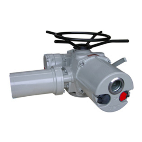
TIANJIN BAILI ERTONG MACHINERY
TIANJIN BAILI ERTONG MACHINERY IMT Series User manual
Popular Controllers manuals by other brands
Maxitrol
Maxitrol 325 Series manual
Harbortronics
Harbortronics DigiSnap 3000 user manual

SMC Networks
SMC Networks ISA3-FCP-4LB-L1 Operation manual
Zennio
Zennio HeatingBOX 24V 4X user manual
Mitsubishi Electric
Mitsubishi Electric MELSEC iQ-F FX5 user manual
Continental Instruments
Continental Instruments CICP1800 datasheet
