TIANJIN BAILI ERTONG MACHINERY XZA Series User manual

(Read this manual carefully before using the products)SM-20
OPERATION MANUAL
XZA Series Electric Actuators
Tianjin Baili Ertong Machinery Co., Ltd.

Contents
1. Overview.......................................................................................................................................1
2. Applicable operating environment................................................................................................1
3. Product structure...........................................................................................................................2
4. Installation.....................................................................................................................................2
5. Electric Wiring..............................................................................................................................2
6. Debugging.....................................................................................................................................5
7. Electrical setting for the integral type of electric actuator ............................................................8
8. How to select priority control mode for valve closing end position ...........................................10
9. Operation inspection after setting...............................................................................................10
10. Notes for use.............................................................................................................................10
11. Outline drawing of XZAexplosion-proof type.........................................................................12

1
1. Overview
XZA series multi-turn type electric valve actuators(hereafter referred to “electric
actuator” for short) are used to drive and control globe valve, gate valve and
diaphragm valve whose discs make straight-line motion during valve opening or
closing.
Having combined with reduction mechanism, the series of electric actuators can be
used to drive and control ball valve, butterfly valve etc, whose discs make ninety
degree turns during valve opening or closing.
XZA series can be divided into five different seating number types and they are
XZA2, XZA3, XZA4, XZA5, and XZA6. Also, XZA series can be divided into basic
type, basic integral type, explosion-proof type and explosion-proof with integral type.
Take the case of XZA2—basic type: XZA2, integral type: XZA2.IN, explosion-proof
type: XZA2Ex, explosion-proof with integral type: XZA2Ex. IN.
This series can be controlled remotely, electrically (operation via control room) or
can be operated electrically or manually on site. If there are some other special
requirements on electric actuators, such as automatic regulation and special protection
etc, we will provide users with relevant instructions to introduce the method of
application and cautions for special parts of the products.
XZA series explosion-proof type is produced on the basis of GB3836.1-2010
《Explosive atmospheres—Part 1: Equipment—General requirements》and
GB3836.2-2010 《Explosive atmospheres —Part 2: Equipment protection by
flameproof enclosures“d”》. Meanwhile, this series have been tested, experimented
and finally verified by the national verified explosion-proof organization and get
Conformity Certificate of Explosion-Proof.
The explosion-proof grade of XZA explosion-proof type is Ex d II B T4 Gb. The
sign “Ex” shows that the electric apparatus comply with the Explosion-proof Standard;
“d” shows that the explosion-proof type is enclosure explosion-proof; II class
represents that electric apparatus used in explosive gas environment except for gas
made from coal; II B represents that the gas is ethylene; T4 indicates that the
permissible surface temperature is 135℃;Gb is apparatus protection degree.
Please refer to this operation manual if user applies XZA series electric actuator,
including the basic type, integral type, explosion-proof type and explosion-proof
integraltype
If users need to know technical parameters of the products, as well as the
dimensions and pattern of the connection platform, please refer to the relevant product
catalog of our company.
2. Applicable operating environment
2.1 This product is in accordance with GB/T24923-2010 Technical Conditions of
Basic Type of Electric Actuator, and GB/T24922-2010 Technical Conditions of
Explosion-proof Type of ElectricActuator
2.2 Power supply: 380V, 50Hz, 3-phase 4-wire system, sine AC; 380V, 50Hz, 3-phase
3-wire system, sine AC (For special voltage and frequency, please refer to product’s

2
nameplate and contract.)
2.3 Protection class: IP67
2.4 Ambient temperature: -20~+60℃
2.5 Relative humidity: be up to 90%(when at 25℃)
2.6 Altitude: be up to 1000m
2.7 Short-time duty: 10mins (rated time)
2.8 Applicable working environment: for basic type, no severe vibration and no strong
corrosive medium and explosive mixed gas in the operating environment; for
explosion-proof type, no strong corrosive medium.
2.9 Electric port: for basic type, total number of M33×1.5 is 2;
forexplosion-proof type, total number of , M33×1.5 on XZA2 is 2.
G1 1/4"on XZA 3~6 is 2.
3. Product structure
3.1 Special motor: YDF or YBDF motor used for electric valve actuator
3.2 Main drive reduction mechanism: worm pair drive mechanism
3.3 Torque control mechanism: mechanical itching switch
3.4 Stroke control mechanism: mechanical counter gear drive mechanism
3.5 Position indication mechanism: mechanical gear drive mechanism
3.6 Manual/electric switching mechanism: electric mechanism is a priority; Electrical
mechanism will be reset after manual operation.
3.7 Local control mechanism: please notify us if users intend to order local control
mechanism; for the basic type and explosion-proof type of XZA series, local control
mechanism is mechanical buttons on the control box cover; for the integral basic type
and explosion-proof integral type of XZA series, the local control mechanism is knob
switch on the side of the electric wiring box cover.
For the controller of the electric valve actuator, controller is a controlling part
which is separated from valve electric actuator. The controller is often set indoors.
Please notify us if users need to order. For structure and function of the controller
please see separate instructions for the controller.
4. Installation
4.1 Installation pattern: There are two installation patterns for electric actuator with
valve: vertical installation (The output shaft of the electric actuator is vertical to the
ground) and horizontal installation (Both output shaft of the electric actuator and shaft
of the motor are parallel to the ground). Horizontal installation is preferred.
4.2 Method of combination/connection with valve: Align the jaw of output shaft of
electric actuator with the driven valve stem’s jaw, and insert teeth of output shaft of
electric actuator into teeth of nut of valve stem and check the mesh. If the mesh is
correct fasten flange screws. You may use in-seam screw to ensure a sound
connection of flange.
5. Electric Wiring
Note: Installation personnel must have the electrician safe operation permits and

3
must operate according to relevant stipulation. Please read this operation manual
carefully before installation. Controlling lines and power lines should be separately
put in the grooves. The output controlling signal lines should apply shield cables and
the shielding layer should be single-end earthed.
5.1 Wiring means of basic type: (basic integral type is the same.)
5.1.1 Open connection box or case of control box with terminal board.
5.1.2 Remove various parts of sealing structure as shown in figure 2. Pull the power
cable and control cable through separate sealing holes and lead the cable ends into
connection cavity.
5.1.3 Connect core wires to the corresponding terminals according to electric control
schematic diagram and comparison table for terminal number and wire number on
schematic diagram. The wire connection should be sound with no bareness.
5.1.4 The grounding core wire of the cable should be connected to grounding screw or
retaining screw for terminal board support inside connection box.
5.1.5 Properly pull the cables out and do not leave to much cable inside connection
box or control box. The cables should be tied up to avoid touching moving parts.
Fig.1
5.1.6 Push parts of sealing structure into the hole where they are held. Fasten the nut
to press rubber sealing ring to make it closely combine with cable sheath, so as to
ensure soundness of cable and tightness of the control cavity. If the tightness is not
satisfied, sealing gum or rubber sealant should be applied.
5.2 Wiring procedure of the explosion-proof type: (Integral, explosion-proof type is
the same.)
5.2.1 Please open No.1 “Wiring box cover” (Fig.1) and remove No.11,12,13,14(Fig.2)
5.2.2 Please select appropriate sealing gasket’s inner diameter according to the cable’s
outer diameter.
5.2.3 Please remove No.13 “solid plate” and pull the cable through No.11 “gland nut”

4
and successively through No.12, 14, 12.
5.2.4 Please connect cable core wire with the wiring fastener on the terminal board.
5.2.5 According to the wiring number of electric schematic diagram, connect the core
wire which with fasteners with the terminal boards correctly. Fasten each gland bolt.
5.2.6 The grounding core wire should be connected with interior grounding bolt.
External grounding core wire should be reliably connected with the actuator’s
grounding bolt or the inlet wire port.
5.2.7 After confirmation of the correctness of the cable wiring, pull the parts
(No.12,14,12,11) successively into wiring box. After adjusting cable’s position (small
part of the cable which is put in the wiring box is preferred.) Fasten the gland
nut.(There are two inlet wiring ports, one of which is used for power cable and the
other is used for control cable. )
5.2.8 Put on the wiring box cover and fasten the gland bolt.
Till now, wiring is finished.
5.3 Cautions:
5.3.1 User must cut off power
when open connection box or
front case shield of the electric
actuator.
5.3.2 You are not allowed to open
case shield outdoors in a rainy day
to prevent electrical parts from
moisture.
5.3.3 Apart from the operation manual, an electric schematic diagram is also provided
in the attached documents. Users should strictly wire according to terminal board. The
connecting plug should not be bare and loosen so as to make sure a reasonable creep
age distance and leakage length.
5.3.4 If No.14 “sealing ring” in Fig.3 is broken, user could ask the factory for a new
one or manufacture by you according to Fig.2.
This should comply with the following technical requirements:
Tensile strength: 70 kg/cm2
Elongation: Above 350%
Hardness: Shore hardness 45-55
Fig.3 Fig.4
Fig.2

5
5.3.5 Cable should be set up correctly to avoid the rain leaking into the electric
actuator (In Fig.3, the first two connection patterns are right.)
6. Debugging
Cautions before debugging:
★The maximum control torque had been set up and sealed off with torque plate for
the products before delivery. There is no need for users to make any adjustment of
torque control mechanism.
★To facilitate user’s adjustment, the stroke control mechanism and position
indication mechanism are normally set to the following state before delivery:
a. The central gear in the driven units should align with the counter’s gear.
b. The potentiometer pinion in position indication mechanism and final pinion of
selective gears are in demising state.
c. Openness pointer is in middle position on the scale.
d. If the position indicating mechanism is T-MDPI, the initial position of the slip
gear is in the minimum turns position. The user needs to move the slide gear to the
corresponding gear range in the digital bar and fasten it firmly according to the actual
number of turns.(See Fig 4)
6.1Primary stroke adjustment
Manually operate the valve to make it be in an optional position of the whole stroke.
Turn on the power and operate the electric actuator for a short time to check, in the
itching type, if the rotating direction is the same as the valve. If not, change and
correct the phase sequence of power before performing the following adjustment.
a. Operate the valve manually to a point where there is only one thread distance from
the closing position.
b. Rotate the counter rod 90°to let it be unscrewed, so as to make the central gear to
disengage and one-digit gear of counter from the engaging state.
c. Clockwise turn closing adjustment shaft of counter to make cam touch closing
microswitch (a click is heard).
d. Unscrew the carrier rod of the counter 90°to make the central gear and one-digit
gear of the counter be in proper meshing state. (Turn the adjustment shaft a little to
check for the meshing, if the meshing is correct the adjustment shaft will not rotate.)
Now the closing position has been primarily adjusted.
e. Manually operate the valve to full open position. (Note: Do not screw down the
carrier rod of the counter in the process.)
f. In the full open position of the valve set down the carrier rod of counter, make
central gear throw out of mesh with one-digit gear of the counter.
g. Turn the opening adjustment shaft of counter counterclockwise to make cam touch
opening microswitch (a click is heard).
h. Unscrew the carrier rod of the counter 90°to make the central gear and one-digit
gear of the counter be in proper meshing state. (Turn the adjustment shaft a little to
check for the meshing, if the meshing is correct the adjustment shaft will not rotate.)
Now the closing position has been primarily adjusted.

6
6.2 Precise stroke adjustment
If, when the valve is electrically operated, the stroke switch controlled end point
position (full closing or full opening) of the valve is unsatisfactory, precise adjustment
should be performed to get perfect position precision. The way of precise adjustment
is to adjust the cam action in a little delay for incomplete opening or closing or to
adjust the cam action in a little advance for a little excess opening or closing.
Precise adjustment of full closing position:
a. If valve closing is incomplete, you should, based on the primary adjustment,
manually operate the valve properly to complete closing position. Then set down the
carrier rod of counter, make central gear throw out of mesh with one-digit gear of the
counter. (Now, closing cam still presses on microswitch.) First turn closing adjustment
shaft anti-clockwise to make closing cam leave microswitch, then turn closing
adjustment shaft clockwise to make closing cam press on microswitch. Afterwards,
turn and lift carrier rod of counter to check the meshing of central gear with one-place
gear of counter. If the meshing is proper, end the adjustment.
b. After valve is closed, torque control switch has acted in advance and closing cam of
stroke switch has not yet pressed on microswitch. In this case, stroke switch action
lags behind torque switch action. If you do not want torque switch to act, you can
manually operate valve to make it properly move to opening direction on the premise
of ensuring valve closing requirement. Then set down carrier rod of counter to make
central gear throw out of mesh with one-digit gear of the counter. (Now, closing cam
does not press on microswitch.) And then turn closing adjustment shaft clockwise to
make closing cam press on microswitch. Afterwards, turn and lift carrier rod of
counter to check the meshing of central gear with one-place gear of counter. If the
meshing is proper, end the adjustment.
6.3 Considerations before and after setting counter
Fig.5
Before setting first check if the cam is in the position shown in Fig.5 and if the
carrier rod has been screwed down.
When performing item e of 6.1 Primary stroke adjustment, if the valve has not
been opened completely but cam has pressed on microswitch, you should stop

7
manual operation, set down carrier rod and turn opening adjustment shaft of
counter clockwise to make cam return to the position shown in Fig.5. And then,
according to the adjustment amount, go on turning the shaft for more turns
clockwise, so as to provide the counter enough adjustment amount. Now turn and
lift carrier rod again and go on with item e.
Upon completion of stroke adjustment, turn and lift carrier rod of counter and
confirm the adjustment. Otherwise, once the electric actuator is in electric mode,
the counter will be out of action; the stroke control will go wrong; the electric
actuator will get into dangerous condition.
6.4 Adjustment for position indication mechanism
a. Setting for the pointer: close the valve before adjusting the stroke mechanism.
Now loosen the fastening screw on pointer and turn the pointer at 0 on the scale, and
then fasten the screw.
b. Potentiometer position setting: when the valve is closed, fasten the fastening
screw on potentiometer gear. With potentiometer gear threw out of mesh with final
pinion, turn the potentiometer until it reaches the end position corresponding to the
valve (The direction must be correct.) and return a little. Loosen the fastening screw
on potentiometer gear, push the gear to make it mesh with the final pinion and fasten
the fastening screw on potentiometer gear. Now the setting of position indication
mechanism is completed.
The setting of the above two steps can also be performed together with the setting
of stroke control.
★ Cautions
a. Pay attention to the determination of potentiometer rotation direction, as wrong
rotation direction will damage the part. When facing the pointer, the rotation direction
(for opening or closing) of potentiometer should be the same as that of the pointer (for
opening or closing).
b. When the position indicating mechanism is T-MDPI, the sliding gears must not be
meshed with two sets of gears at the same time. Otherwise, the mechanism may be
damaged!(See Fig.4)
c. When the position indicating mechanism is T-MDPI, the gear position of the
adjustment and positioning of sliding gear should be not less than and close to the
required number of turns! (See Fig.4)
6.5 About the local control mechanism
★ For basic type and explosion-proof type of electric actuator, the local control
mechanism is mechanical buttons which are on the control box cover. When local
control is needed, user needs to switch the control mode to local control and then,
push the open or close button according to user’s need. Push any button successively,
the electric actuator would operate the opening process or closing process; when user
leaves his grip on the button, button will automatically back again and actuator will
also stop operating.(Please switch control mode into remote control while local
control is finished.)
★ For the integral type and explosion-proof, integral type of electric actuator, its

8
local control mechanism is knobs on the side of electric wiring box. Please refer to
7.2.4 for operating methods.
7. Electrical setting for the integral type of electric actuator
XZA series include basic integral type and explosion-proof integral type.
7.1 Features:
7.1.1 Identify the phase sequence automatically; open-phase protection
7.1.2 DC24V is applied in remote control
7.1.3 A convenient, flexible wiring methods for users
7.1.4 The switch of the local control buttons applies Hall element, and it is applied
with a blind design which is of a high tightness.
7.1.5 Five dry contacts indicate working condition of the actuator, which provides
convenience for DCS System’s control on the actuator.
7.1.6 Set up the actuator’s supervisory relay in order to provide a comprehensive
failure signal for DCS System.
7.1.7 Automatically setting for the valve’s output current from zero to full(this is
applied for those which with output current and those adjusting type)
7.1.8 Switch knob could be locked by ordinary padlock, if needed, in case of human’s
mal-operation.
7.2 Debugging
7.2.1 Please make a reference to the electric schematic diagram in the attachment.
7.2.2 “Power/Malfunction” indicator on the local control buttons shows green light
after power is on.
7.2.3 Please make a reference to “6 Debugging” to adjust the stroke control
mechanism and position indication mechanism.
7.2.4 Local control and adjustment (Please refer to the attached electric schematic
diagram)
Turn the change over button to the
“local”(shown in Fig.6, the bigger button on
the bottom of the indicator box is change over
button; on the top is the switch button).
“Local/Remote” button’s indicator is red,
which means the electric actuator is locally
operated.
Turn the switch knob counterclockwise, the
actuator will run to the opening direction, and
the “valve on/valve off” indicator flashes red
light. When the electric actuator is turned on
until it stops at the fully open position, the
“valve on/valve off” indicator light is red, the
“dry contact common end” and “open to
position” have a closed dry contact output Fig.6

9
(open-to-position dry output contact), and the current end of valve position “O+” and
“O-” output at the same time have a current output of 20mA (with current output and
modulating type is applicable).
Turn the switch knob clockwise, the actuator will run to the closing direction, and
the “valve on/valve off” indicator flashes green light. The electric actuator is turned
off until it stops at the fully close position, the "valve on/valve off" indicator is green,
and the "dry contact common end" and "close to position" have a closed dry contact
output (close to position dry output contact). The current end of valve position “O+”
and “O-”output at the same time have 4mA current output (with current output and
modulating type is applicable). When the electric actuator is in local working state,
the electric actuator is in on or off running state, release the switch knob and the
electric device will stop at this instant position.
While the actuator is operating, maybe due to a jammed valve or some other
reasons, over-torque is happened and then, the actuator will be protected and stop
working. There is dry contact closure (passive output torque contact) between “dry
contact common port” and “over-torque”. “Power/Malfunction” button’s indicator is
red; at the same time, a corresponding indicator should flash (flashing frequency is
lower than that of when the actuator’s operating). Supervisory relay is set in the
integral type of actuator. The supervisory relay would be excited when actuator is
normally working. The supervisory relay would be de-energized(non-excited state)
when some thing just happened and influenced actuator( change button is turned to
“stop” or, when power is off, loss of phase, motor has over-current or over-heated).
7.2.5 Control and adjustment for remote switch valve
Turn the change over button to “Remote” and then “Local/Remote” button’s
indicator is green; the actuator is remotely controlled. There is a dry contact closure
(dry contact in remote control) between “Dry contact common port” and “Remote”.
Select a proper wiring method from the attachment according to the remote control
electric schematic diagram. A corresponding indicator is flashing when actuator is
working.
7.2.6 Control and adjustment for analog signal input (applied for the adjustment type
of actuator)
Connect the ampere meter with the port of current of valve position “O+” and
“O-”in order to supervise valve’s position output. Short-circuit the remote analog
control (eg. Electric schematic diagram zq3e, No.5) and control common port (eg.
Electric schematic diagram zq3e, No.6) and then, connect the analog control signal,
which is from remote control system, (4-20mA) with input current port of the actuator
“I+” and “I-”. Adjust the input control current from 4mA to 20mA. The actuator starts
from the input tracking signal of closure position and stops at the fully open position.
Meanwhile, the valve position signal changes with 4~20mA. On the contrary, when
the input control signal changes from 20~4mA, the actuator starts from input
tracking signal of open position to the fully closed position, with the output valve
position signal changing from 20mA to 4mA. Under the control of analog signal is
broken, there are three conditions: 1. Stay-put. 2. Stopped at the fully open position. 3.
Stopped at fully closed position. Factory default is stay-put, No.2 and 3 can be

10
provided as user required.
8. How to select priority control mode for valve closing end position
Both stroke control and torque control can control valve closing. Take one as
priority control and the other as protective control. Select different priority control
mode for different types of valve. For wedge gate valve and cut-off valve etc, it is
recommended to take torque control as priority control and stroke control as
secondary protective control. While for general flat or parallel gate valve, it is
recommended to take stroke control as priority control and torque control as
secondary protective control.
9. Operation inspection after setting
After completion of setting, the electric actuators can not be used until they passed
the following inspections.
9.1 After valve is closed electrically to the position, the control mechanism can
normally cut off the power and ensure the sealing requirement of the valve. After the
valve is set to the fully open position, the power can be cut off precisely and reliably.
9.2 Position indication mechanism can properly show the operation condition of the
valve.
9.3 Manual switching mechanism should work reliably and electrical reset is flexible
and reliable. Before manual operation, push on the switch hand and rotate handwheel
until the switch hand is turned to the right place, which means manual/electrical
switch is finished. Rotate the handwheel if manual operation is needed. Under the
electrical mode, the switch hand will automatically turn to the electrical position.
Note: The switch hand is forbidden to turn from manual operation position
to electrically operation position in case of damaging the actuator.
10. Notes for use
10.1 Don’t hit the openness window glass and glass crack is forbidden.
10.2 Keep the nameplate and warning plate being fixed on actuator and the words on
them should be recognized.
10.3 Don’t open the electric box cover outdoors in rainy day or windy day.
10.4 Power must be cut off when actuator’s any cover is open.(please see the warning
plate: “Forbid to open the box cover when the power is on.”)
10.5 Please check power’s phase sequence before debugging the product. Wiring
should be correctly operated.
10.6 The product’s explosion-proof cover cannot be knocked or scratched during
maintenance or debugging.
10.7 Apply anti-rust painting 204-1 after debugging or maintenance and before
assembling.
10.8 Please notify the company to change the broken explosion-proof elements. The
products cannot be powered on until it is renewed with qualified element.
10.9 Forbid to turn the switch hand strongly to the last position after using the

11
manual/electrical handwheel, in case that the actuator would be damaged.
10.10 Fasten the screws on the control box cover and wiring box cover after product
debugging. After some strong vibration, please make regular check to make sure
whether it is reliable. Sealing structure cannot be damaged at the same time. Tightness
should be confirmed.
10.11 Don’t dismantle at will or adjust any irrelevant part of the product.
10.12 If the product is seldom used, please make a regular electrical check if working
condition is permitted.
10.13 The eyebolts on the electric actuator are only for lifting the actuator. Do not lift
the actuator with valve via the eyebolts.
10.14 After service-disassembly of the product both torque control mechanism and
stroke control mechanism should be re-calibrated and set.
10.15 Special lubrication had been added to the electric actuators before delivery. If
change is needed, specialized lubrication is recommended.
10.16 Grounding screw should be properly connected.
10.17 The design service life of actuator is 8000 times.
10.18 According to the regulations on the recycling and treatment of waste electrical
and electronic products, please comply with the relevant national regulations and
properly dispose of waste products. Or call our after-sales service department for
recycling. Tel: 022-26740033.

12
11. Outline drawing of XZA explosion-proof type
Fig.7

13
Fig.8

Special Cautions
In order to ensure the protective performance of the case of the whole electric
actuator, users must strictly follow the requirements in the Operation Manual and in
this Special Cautions while performing relevant operations when they set and service
the actuators. If users failed to follow the regulations in the Operation Manual and the
Special Cautions while performing relevant operation and have resulted in fail-safe
protection of the case of the electric actuators, the users shall bear the responsibility.
Before delivery all locations related to case protection of the products have been
strictly inspected to ensure that the case is airtight. If users need to open the following
locations for setting, service or any other reasons:
Case of control box
Case of connection box
At places where wire comes in and goes out, it must be ensured that:
1. There is no affect of adverse elements such as rain, snow, hail, damp and dust, etc.
as the electric actuator will lose original protection function in the above conditions.
2. At the end of operation, replace the cover. When fastening the clamp nuts at wire
inlet and outlet, make sure that no adverse elements (such as severe damp, water and
dust, etc.) that could weaken protective performance left in the inner space.
3. In the course of mounting covers, make sure that rubber seal rings are not damaged
and fasteners are securely screwed down without any omission.
4. After cable comes out of connecting sleeve, securely fasten the clamp nuts, and the
gap between clamp nuts and box must be sealed by winding with sealing tape, and
meanwhile sealant (such as 609) or rubber dough must be applied between cable and
clamp nuts.
5. After disassembly and reassembly of parts on some other locations, such as opening
window or on-site button etc, for some reason, users shall make sure that there will be
no adverse effect on the sealing result.
Tianjin Baili Ertong Machinery Co., Ltd.
Address: Block B,No.180 Hanghai Road, Tianjin Pilot Free Trade Zone (Airport Economic Zone)
Tel:86 22 26750313,84911766,84911866
Fax:86 22 26330054,26750339,26770821
Zip code: 300300
http://www.tet.cn
Email: scb@tet.cn
Our Company reserves the right to amend this operation manual.
This manual suits for next models
5
Table of contents
Other TIANJIN BAILI ERTONG MACHINERY Controllers manuals
TIANJIN BAILI ERTONG MACHINERY
TIANJIN BAILI ERTONG MACHINERY IMT Series User manual
TIANJIN BAILI ERTONG MACHINERY
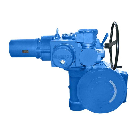
TIANJIN BAILI ERTONG MACHINERY QBR3 User manual
TIANJIN BAILI ERTONG MACHINERY
TIANJIN BAILI ERTONG MACHINERY SMC Series User manual
TIANJIN BAILI ERTONG MACHINERY
TIANJIN BAILI ERTONG MACHINERY NQB1 User manual
Popular Controllers manuals by other brands

ZyXEL Communications
ZyXEL Communications NXC2500 quick start guide
Mitsubishi Electric
Mitsubishi Electric MELSEC iQ-F FX5 user manual

Unitronics
Unitronics Vision V570-57-T40B installation guide
Siemens
Siemens Simatic S7-1500 System manual

Cypress
Cypress CY3280-BK1 quick start guide
Lightware
Lightware RAP-B511-EU user manual
