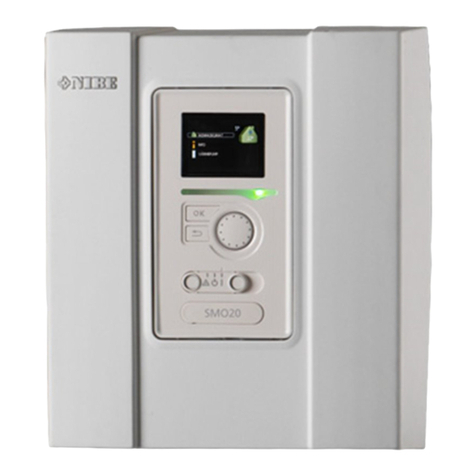
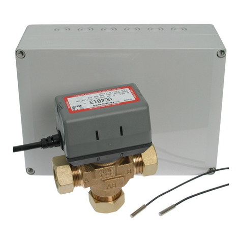
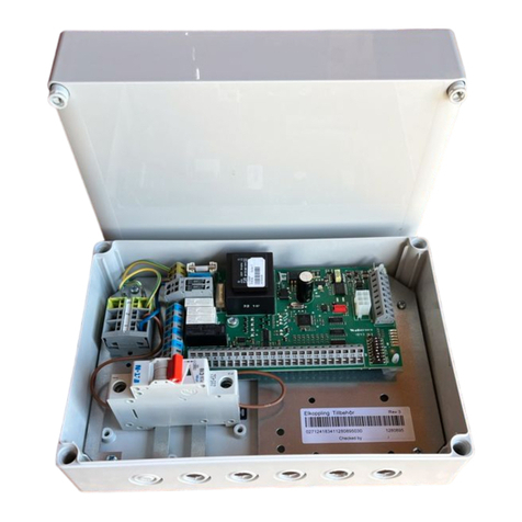
Nibe VST 11 User guide

Installatörshandbok Varmvattenstyrning
SE
Installer manual Hot water control
GB
Installateurhandbuch Brauchwassersteuerung
DE
Asentajan käsikirja Lämmityksen ohjaus
FI
IHB 2047-13
011023
VST 11
LEK


Svenska
4Viktig information
5Allmänt
6Principschema
7Montering
8Elinkoppling
9Tekniska data
English
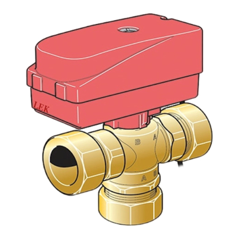
10Important information
11General
12Outline diagram
13Mounting
14Electrical connection
15Technical specifications
Deutsch
16Wichtige Informationen
17Allgemeines
18Prinzipskizze
19Montage
20Elektrischer Anschluss
21Technische Daten
Suomi
22Tärkeää
23Yleistä
24Periaatekaavio
25Asennus
26Sähköasennukset
27Tekniset tiedot
31Kontaktinformation
3VST 11
Table of Contents

Viktig information
SÄKERHETSINFORMATION
Denna handbok beskriver installations- och servicemo-
ment avsedda att utföras av fackman.
Handboken ska lämnas kvar hos kunden.
Apparaten får användas av barn över 8 år
och av personer med fysisk, sensorisk eller
mental funktionsnedsättning samt av per-
soner som saknar erfarenhet eller kunskap
under förutsättning att de får handledning
eller instruktioner om hur man använder
apparaten på ett säkert sätt och informeras
så att de förstår eventuella risker. Barn får
inte leka med apparaten. Låt inte barn
rengöra eller underhålla apparaten utan
handledning.
Med förbehåll för konstruktionsändringar.
©NIBE 2020.
SYMBOLER
OBS!
Denna symbol betyder fara för människa eller
maskin.
TÄNK PÅ!
Vid denna symbol finns viktig information om
vad du ska tänka på när du installerar eller ser-
var anläggningen.
TIPS!
Vid denna symbol finns tips om hur du kan
underlätta handhavandet av produkten.
MÄRKNING
CE-märket är obligatoriskt för de flesta produkter
som säljs inom EU, oavsett var de är tillverkade.
CE
Klassificering av inkapsling av elektroteknisk ut-
rustning.
IP 21
Läs installatörshandboken.
VST 11 | SE4
Svenska

Allmänt
Växelventil VST 11 gör det möjligt att använda varmvat-
tentillbehör i olika system tillsammans med NIBE värme-
pumpar. För detta krävs också en varmvattenackumula-
tor, till exempel NIBE VPB eller VPA.
KOMPONENTER
LEK
QN10
A
B
AB
QN10 Växelmotor + växelventil
FUNKTION
Vid varmvattenbehov styrs laddningsflödet mot varmvat-
tenackumulatorn med hjälp av växelventilen (QN10). I
övriga fall styrs laddningsflödet mot återstående delar i
systemet, till exempel värmesystem.
Se principschema sida 6.
POOLUPPVÄRMNING
Växelventilen (QN19) kan med liknande funktion använ-
das för styrning av pooluppvärmning. För information
om pooluppvärmning och principscheman för dockning,
se nibe.se/dockning.
5VST 11 | SE

Principschema
Verklig anläggning ska projekteras enligt gällande nor-
mer. Fler systemprinciper finns på nibe.se/dockning.
FÖRKLARING
VarmvattengivareBT6
ElvarmvattenberedareEB2
SmutsfilterHQ1
Avstängningsventil, värmebärare framQM31
Avstängningsventil, värmebärare returQM32
VäxelventilQN10
Övrigt
Varmvattenberedare/AckumulatorCP1
Anslutning, kallvattenXL3
Anslutning, varmvattenXL4
El VVB
VVG
KV VV
Radiator
Fram
Radiator
Retur
VXV
B
AB
A
SF
AV
AV
VB-fram
VB-retur
Givarkabel till Värmepump
19
88
VVB / ACK
B
AB
A
QN10
QM31
QM32 HQ1
BT6
CP1
XL3 XL4
EB2
Värmepump
VST 11 | SE6

Montering
Växelventilen (QN10) monteras mellan värmekälla och
varmvattenackumulator/övrigt system. I utgångsläge,
utan manöverspänning, ska växelventilen vara öppen
mot övrigt system. När manöverspänning är påslagen
öppnas växelventilen mot varmvattenackumulatorn.
MONTERING AV VENTILMOTOR
1. Fäst ventilmotorn (A) med förmonterad fjäder på
ventilen
2. Tryck ner ventilmotorn till dess att ett klickande ljud
hörs. Då är motorn låst mot ventilen.
LEK
A
DEMONTERING
Dra ut fjädern (B) och ta isär komponenterna. Se nedan
bild.
LEK
B
7VST 11 | SE

Elinkoppling
OBS!
Elinstallation samt eventuell service ska göras
under överinseende av behörig elinstallatör.
Bryt strömmen med arbetsbrytaren innan
eventuell service. Elektrisk installation och
ledningsdragning ska utföras enligt gällande
bestämmelser.
• För att undvika störningar får givarkablar till externa
anslutningar inte förläggas i närheten av starkströms-
ledningar.
• Minsta area på kommunikations- och givarkablar till
extern anslutning ska vara 0,5 mm² upp till 50 m, till
exempel EKKX, LiYY eller liknande.
• VST 11 ska installeras via allpolig brytare. Kabelarea
ska vara dimensionerad efter vilken avsäkring som
används.
• Märk upp aktuell ellåda med varning för extern spän-
ning, i de fall någon komponent i lådan har separat
matning.
• VST 11 återstartar efter spänningsbortfall.
KABELLÅSNING
Använd lämpligt verktyg för att lossa/låsa fast kablar
i plintar.
LEK
1
1
2
2
3
3
1
2
3
3
4
1
2
LEK
1
1
2
2
3
3
1
2
3
3
4
1
2
1
2
Ventilmotorn ansluts enligt nedan schema.
Brun
1 ~
L
Noll
Styrfas
MBlå
Svart
QN10
För mer information om elanslutningar, se aktuell instal-
lationshandbok/monterings- och skötselanvisning för
det system som växelventilen ska anslutas till.
VST 11 | SE8

Tekniska data
VST 11
230V~50 HzSpänning
17kWkWMax laddeffekt
28mm, KlämringØKopplingar
7,5Kvs
8sGångtid
7 (under drift)WEffektförbrukning
IP54Kapslingsklass
089 152Art. nr
9VST 11 | SE

Important information
SAFETY INFORMATION
This manual describes installation and service proced-
ures for implementation by specialists.
The manual must be left with the customer.
This appliance can be used by children
aged from 8 years and above and persons
with reduced physical, sensory or mental
capabilities or lack of experience and
knowledge if they have been given super-
vision or instruction concerning use of the
appliance in a safe way and understand
the hazards involved. Children shall not
play with the appliance. Cleaning and user
maintenance shall not be made by children
without supervision.
Rights to make any design or technical
modifications are reserved.
©NIBE 2020.
SYMBOLS
NOTE
This symbol indicates danger to person or ma-
chine .
Caution
This symbol indicates important information
about what you should consider when installing
or servicing the installation.
TIP
This symbol indicates tips on how to facilitate
using the product.
MARKING
The CE mark is obligatory for most products sold
in the EU, regardless of where they are made.
CE
Classification of enclosure of electro-technical
equipment.
IP 21
Read the Installer Manual.
VST 11 | GB10
English

General
The VST 11 reversing valve gives you the option to use
hot water accessories in different systems together
with NIBE heat pumps. This also requires a hot water
accumulator, for example, NIBE VPB or VPA.
COMPONENTS
LEK
QN10
A
B
AB
QN10 Valve motor + reversing valve
FUNCTION
When there is hot water demand the charge flow is
guided to the hot water accumulator using the reversing
valve (QN10). In other cases the charge flow is con-
trolled through the remaining parts of the system, for
example the heating system.
See the outline diagram on page 12.
POOL HEATING
The reversing valve (QN19) with a similar function can
be used to control pool heating. For information about
pool heating and outline diagrams for docking, see
nibe.eu.
11VST 11 | GB

Outline diagram
Real installations must be planned according to applic-
able standards. More system principles can be found at
nibe.eu.
EXPLANATION
Hot water sensorBT6
Electric water heaterEB2
Particle filterHQ1
Shut-off valve, heating medium flowQM31
Shut off valve, heating medium returnQM32
Shuttle valveQN10
Miscellaneous
Hot water heater/AccumulatorCP1
Connection, cold waterXL3
Connection, hot waterXL4
El VVB
VVG
KV VV
Radiator
Fram
Radiator
Retur
VXV
B
AB
A
SF
AV
AV
VB-fram
VB-retur
Givarkabel till Värmepump
19
88
VVB / ACK
B
AB
A
QN10
QM31
QM32 HQ1
BT6
CP1
XL3 XL4
EB2
Heat pump
VST 11 | GB12

Mounting
The reversing valve (QN10) is always installed between
the heat source and the hot water accumulator/rest of
the system. In the starting mode, without control
voltage, the reversing valve must be open to the rest of
the system. When control voltage is applied the revers-
ing valve opens to the hot water accumulator.
INSTALLING THE VALVE MOTOR
1. Secure the valve motor (A) with a preinstalled spring
on the valve.
2. Press the valve motor down until a click is heard.
The motor is then locked to the valve.
LEK
A
DISMANTLING
Pull out the spring (B) and remove the components. See
image below.
LEK
B
13VST 11 | GB

Electrical connection
NOTE
Electrical installation and service must be car-
ried out under the supervision of a qualified
electrician. Cut the current with the circuit
breaker before carrying out any servicing.
Electrical installation and wiring must be carried
out in accordance with the stipulations in force.
• To prevent interference, sensor cables to external
connections must not be laid close to high voltage
cables.
• The minimum area of communication and sensor
cables to external connections must be 0,5 mm² up
to 50 m, for example EKKX, LiYY or equivalent.
• VST 11 must be installed via an isolator switch. The
cable area has to be dimensioned based on the fuse
rating used.
• Mark the relevant electrical cabinet with a warning
about external voltage, in those cases where a com-
ponent in the cabinet has a separate supply.
• VST 11 restarts after a power failure.
CABLE LOCK
Use a suitable tool to release/lock cables in terminal
blocks.
LEK
1
1
2
2
3
3
1
2
3
3
4
1
2
LEK
1
1
2
2
3
3
1
2
3
3
4
1
2
1
2
The valve motor is connected according to the following
diagram.
Brown
1 ~
L
Neutral
Control phase
MBlue
Black
QN10
For more information about electrical connections, see
relevant Installer manual/Assembly and maintenance
instructions for the system to which the reversing valve
is to be connected.
VST 11 | GB14

Technical specifications
VST 11
230V~50 HzVoltage
17kWkWMax. charge power
28mm, Compression ringØConnections
7,5Kvs
8secRun time
7 (during operation)WPower consumption
IP54Enclosure class
089 152Part No.
15VST 11 | GB

Wichtige
Informationen
SICHERHEITSINFORMATIONEN
In diesem Handbuch werden Installations- und Service-
vorgänge beschrieben, die von Fachpersonal auszufüh-
ren sind.
Dieses Handbuch verbleibt beim Kunden.
Dieses Gerät darf von Kindern ab einem
Alter von 8 Jahren sowie von Personen
mit eingeschränkten physischen, sensori-
schen oder geistigen Fähigkeiten oder
mangelnden Erfahrungen und Wissen nur
dann verwendet werden, wenn diese unter
Aufsicht stehen oder eine Anleitung zur
sicheren Benutzung des Geräts erhalten
haben und sich der vorhandenen Risiken
bewusst sind. Kinder dürfen nicht mit dem
Gerät spielen. Eine Reinigung und Wartung
durch den Benutzer darf nicht von Kindern
ohne Aufsicht ausgeführt werden.
Technische Änderungen vorbehalten!
©NIBE 2020.
SYMBOLE
HINWEIS!
Dieses Symbol kennzeichnet eine Gefahr für
Personen und Maschinen.
ACHTUNG!
Dieses Symbol verweist auf wichtige Angaben
dazu, was bei Installation oder Wartung der
Anlage zu beachten ist.
TIPP!
Dieses Symbol kennzeichnet Tipps, die den
Umgang mit dem Produkt erleichtern.
KENNZEICHNUNG
Die CE-Kennzeichnung ist für die meisten inner-
halb der EU verkauften Produkte vorgeschrieben
– unabhängig vom Herstellungsort.
CE
Klassifizierung des Gehäuses als elektrotechni-
sche Ausrüstung.
IP 21
Lesen Sie das Installateurhandbuch.
VST 11 | DE16
Deutsch

Allgemeines
Das Umschaltventil VST 11 ermöglicht die Nutzung von
Brauchwasserzubehör in verschiedenen Systemen ge-
meinsam mit NIBE-Wärmepumpen. Dafür ist ebenfalls
ein Brauchwasserspeicher erforderlich, z.B. NIBE VPB
oder VPA.
KOMPONENTEN
LEK
QN10
A
B
AB
QN10 Getriebemotor + Umschaltventil
FUNKTION
Bei einem Brauchwasserbedarf wird der Ladevolumen-
strom zum Brauchwasserspeicher mithilfe des Umschalt-
ventils (QN10) geregelt. Ansonsten wird der Ladevolu-
menstrom zu den übrigen Teilen des Systems geleitet,
z.B. zum Heizsystem.
Siehe Prinzipskizze auf Seite 18.
POOLERWÄRMUNG
Das Umschaltventil (QN19) kann mit einer ähnlichen
Funktion zur Steuerung der Poolerwärmung genutzt
werden. Informationen zur Poolerwärmung und eine
Prinzipskizze für den Anschluss finden Sie unter nibe.de.
17VST 11 | DE

Prinzipskizze
Die tatsächliche Anlage muss gemäß den geltenden
Normen geplant werden. Weitere Systemprinzipien fin-
den Sie hier: nibe.de.
ERKLÄRUNG
BrauchwasserfühlerBT6
ElektrobrauchwasserspeicherEB2
SchmutzfilterHQ1
Absperrventil, HeizungsvorlaufQM31
Absperrventil, HeizungsrücklaufQM32
WechselventilQN10
Sonstiges
Brauchwasserspeicher/SpeicherCP1
KaltwasseranschlussXL3
Anschluss, BrauchwasserXL4
El VVB
VVG
KV VV
Radiator
Fram
Radiator
Retur
VXV
B
AB
A
SF
AV
AV
VB-fram
VB-retur
Givarkabel till Värmepump
19
88
VVB / ACK
B
AB
A
QN10
QM31
QM32 HQ1
BT6
CP1
XL3 XL4
EB2
Wärmepumpe
VST 11 | DE18

Montage
Das Umschaltventil (QN10) wird zwischen Wärmequelle
und Brauchwasserspeicher/restlichem System montiert.
In der Ausgangsstellung, ohne Steuerspannung, muss
das Umschaltventil zum restlichen System geöffnet
sein. Bei anliegender Steuerspannung wird das Umschalt-
ventil zum Brauchwasserspeicher geöffnet.
MONTAGE DES VENTILMOTORS
1. Befestigen Sie den Ventilmotor (A) mit der vormon-
tierten Feder am Ventil.
2. Drücken Sie den Ventilmotor nach unten, bis ein
Klickgeräusch zu hören ist. In diesem Fall ist der
Motor am Ventil eingerastet.
LEK
A
DEMONTAGE
Ziehen Sie die Feder (B) heraus und demontieren Sie
die Komponenten. Siehe Abbildung unten.
LEK
B
19VST 11 | DE

Elektrischer Anschluss
HINWEIS!
Elektrische Installation sowie eventuelle Ser-
vicearbeiten müssen unter Aufsicht eines
ausgebildeten Elektroinstallateurs erfolgen.
Unterbrechen Sie vor etwaigen Servicearbeiten
die Stromversorgung per Betriebsschalter. Bei
der elektrischen Installation und beim Verlegen
der Leitungen sind die geltenden Vorschriften
zu berücksichtigen.
• Um Störungen zu vermeiden, dürfen Fühlerkabel für
externe Schaltkontakte nicht in der Nähe von Stark-
stromleitungen verlegt werden.
• Der minimale Kabelquerschnitt der Kommunikations-
und Fühlerkabel für einen externen Schaltkontakt muss
0,5 mm² bis zu 50 m betragen, z.B. EKKX, LiYY o.s.ä.
• VST 11 muss über einen allpoligen Schalter installiert
werden. Der Kabelquerschnitt muss der verwendeten
Absicherung entsprechend dimensioniert sein.
• Bringen Sie am betreffenden Schaltschrank eine
Warnung vor externer Spannung an, falls darin befind-
liche Komponenten eine separate Spannungsversor-
gung haben.
• VST 11 startet nach einem Spannungsausfall neu.
KABELARRETIERUNG
Verwenden Sie zum Lösen bzw. Befestigen von Ka-
beln an den Anschlussklemmen ein geeignetes
Werkzeug.
LEK
1
1
2
2
3
3
1
2
3
3
4
1
2
LEK
1
1
2
2
3
3
1
2
3
3
4
1
2
1
2
Der Ventilmotor wird gemäß dem folgenden Schema
angeschlossen.
Braun
1 ~
L
Null
Steuerungsphase
MBlau
Schwarz
QN10
Weitere Informationen zu elektrischen Anschlüssen
entnehmen Sie der jeweiligen Installations- bzw. Mon-
tage- und Wartungsanleitung für das System, mit dem
das Umschaltventil verbunden werden soll.
VST 11 | DE20
Other manuals for VST 11
1
Table of contents
Languages:
Other Nibe Controllers manuals
Popular Controllers manuals by other brands

Bender
Bender CC612 EV quick start guide

Adaptec
Adaptec 29320-R - SCSI Card RAID Controller installation guide

Sturtevant Richmont
Sturtevant Richmont Programmable Torque Verifier FM II owner's manual

RainPoint
RainPoint TTV102B user manual

Viconics
Viconics VT8000 Series installation guide

Globe Scientific
Globe Scientific Diamond SeroFlow 3385 quick start guide

BBH
BBH SCU Series installation manual

Musica
Musica MUSICAVC-50Z installation instructions

Emerson
Emerson TARTARINI PS/80-1 instruction manual

Munters
Munters Trio Poultry Controller installation manual

Trane
Trane Tracer ZN517 Installation and operation

Advanced Energy
Advanced Energy Thyro-PX Series user manual