tibelec 976130 User manual
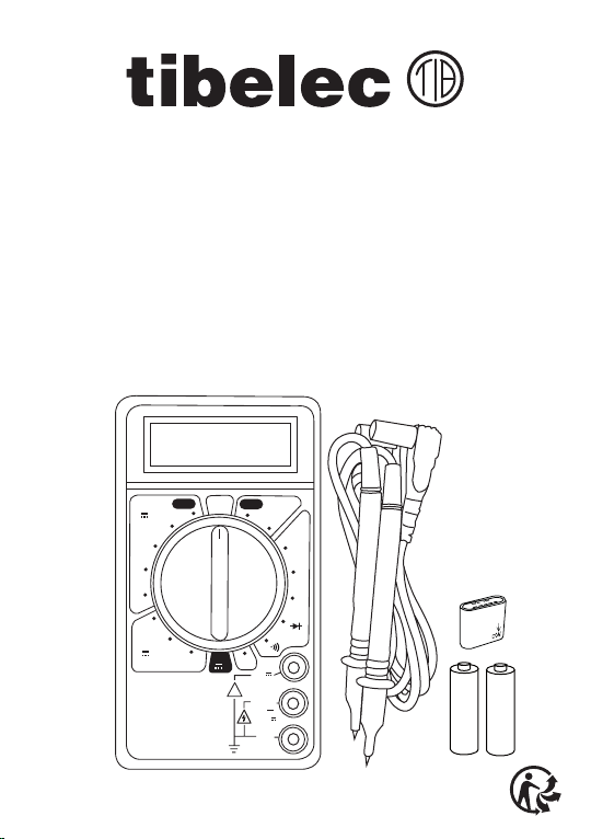
Digi-testeur REF 976130/
DT830D
VIM : 21600_20W06
FR/ Notice d’utilisation - GB/ Instructions
ES/ Manual de uso - IT/ Istruzioni per l’uso
PT/ Manual de instruções - DE/ Gebrauchsanweisung
NL/ Instructies voor gebruik - PL/ Instrukcje użytkowania
RO/ Instrucțiuni de utilizare - GR/ οδηγίες χρήσης
200
20
2000
m
200m
250
250 250
200
2000
µ
20m 200
2000
20k
200k
2000k
10A
Ω
VV
A
OFF
10A
~
MAX 10 sec
EACH 15 min
FUSED
COM
VΩmA
!
200m
hFE
hFE
250V
200mA
FUSED MAX
~
LR03/
AAA
1,5V
-
+
LR03/
AAA
1,5V
-
+

FR
2
Avertissement :
1. Soyez particulièrement prudent en présence de tensions supérieures à 30VACrms
ou 60VDC pour éviter des dommages ou électrocutions
2. Ne jamais appliquer une valeur d’entrée supérieure à la valeur maximum de la
gamme autorisée par le fabricant de l’appareil. Ce testeur est destiné à des appli
cations de basse tension. (250V MAXI EN ALTERNATIF/CONTINU )
3. Ne jamais utiliser le testeur pour mesurer la ligne alimentant un appareil qui
génère une montée subite de la tension puisqu’elle peut excéder la tension maxi
male permise (exemple des moteurs)
4. Ne jamais utiliser le testeur si les pointes ou cordons de mesure sont endommagés
ou cassés. Veillez à ce qu’ils ne soient jamais humides ou mouillés ; vériez le bon
état de fonctionnement du testeur et celui des cordons avant sa mise en service.
5. L’ouverture du boîtier donne accès à des parties conductrices de tensions dange
reuses. Toute action sur les circuits internes pourrait entraîner une utilisation dan
gereuse. Ne jamais utiliser le testeur démonté. Avant d’utiliser votre testeur :
vériez que le boîtier est bien fermé et vissé.
6. Laissez toujours vos doigts derrière la garde des pointes test lors des mesures.
Veillez au cours de la mesure à ne pas entrer en contact (par les doigts par
exemple) directement ou indirectement avec les parties conductrices de tensions
élevées.
7. Avant toute intervention (changement de piles, par exemple) ou avant de tourner
le sélecteur rotatif pour changer de fonction, déconnectez les pointes des cordons
de toute source de tension et du circuit à mesurer et éteindre le testeur.
8. Avant d’effectuer une mesure, assurez-vous que le sélecteur de fonction est en
position correcte.
IMPORTANT : ces instructions sont pour votre sécurité.
Lisez les attentivement avant utilisation et conservez-les
pour une utilisation ultérieure.
3
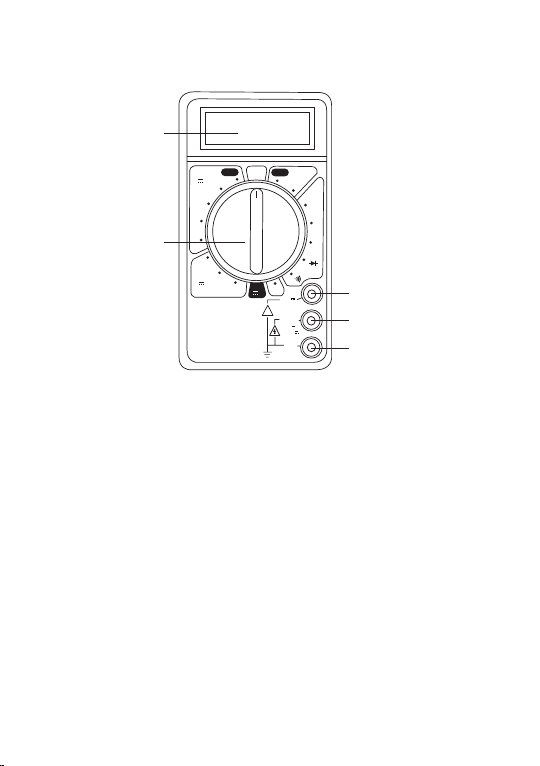
1. Afchage LCD
2. Sélecteur de fonctions
3. Jack 10A cordon rouge
4. Jack VΩmA cordon rouge
5. Jack COM cordon noir
• Afchage LCD : lecture maxi 1999
• Commutateur de fonction : voltmètre alternatif, ohmmètre, test de diodes, continuité
avec buzzer, hFE transistor, ampéremètre en continu, voltmètre en continu.
200
20
2000
m
200m
250
250 250
200
2000
µ
20m 200
2000
20k
200k
2000k
10A
Ω
VV
A
OFF
10A
~
MAX 10 sec
EACH 15 min
FUSED
COM
VΩmA
!
200m
hFE
hFE
250V
200mA
FUSED MAX
~
1
2
3
4
5

4
V
DCV
V~
ACV
Utilisation :
Ω
Tension alternative AC
de 0 à 250V
Tension continue DC
de 0 à 250V
Intensité continue DC
de 0 à 10A
A
Résistance
(Ohmmètre)
de 0 à 2MΩ
Continuité
avec buzzer
+
-
200
20
2000
m
200m
250
250 250
200
2000
µ
20m 200
2000
20k
200k
2000k
10A
Ω
VV
A
OFF
10A
~
MAX 10 sec
EACH 15 min
FUSED
COM
VΩmA
!
200m
hFE
hFE
250V
200mA
FUSED MAX
~
200
20
00
m
250
O
200
20
2000
m
200m
250
250 250
200
2000
µ
20m 200
2000
20k
200k
2000k
10A
Ω
VV
A
OFF
10A
~
MAX 10 sec
EACH 15 min
FUSED
COM
VΩmA
!
200m
hFE
hFE
250V
200mA
FUSED MAX
~
250
250
200
V
OFF
+
-
batterie
200
20
2000
m
200m
250
250 250
200
2000
µ
20m 200
2000
20k
200k
2000k
10A
Ω
VV
A
OFF
10A
~
MAX 10 sec
EACH 15 min
FUSED
COM
VΩmA
!
200m
hFE
hFE
250V
200mA
FUSED MAX
~
20m
10A
200m
200
20
2000
m
200m
250
250 250
200
2000
µ
20m 200
2000
20k
200k
2000k
10A
Ω
VV
A
OFF
10A
~
MAX 10 sec
EACH 15 min
FUSED
COM
VΩmA
!
200m
hFE
hFE
250V
200mA
FUSED MAX
~
200
200k
2000k
Ω
200
20
2000
m
200m
250
250 250
200
2000
µ
20m 200
2000
20k
200k
2000k
10A
Ω
VV
A
OFF
10A
~
MAX 10 sec
EACH 15 min
FUSED
COM
VΩmA
!
200m
hFE
hFE
250V
200mA
FUSED MAX
~
200
200
20
A
hFE

5
1. Reliez la sonde noire à la borne COM et la sonde rouge à la borne VΩmA
2. Mettez le commutateur de fonction sur le calibre de tension continue voulu
3. Connectez les pointes test sur le circuit et lisez la valeur indiquée à l’écran quand elle
est stabilisée. Lorsque vous mesurez une tension continue, l’écran afche la polarité
de la sonde rouge.
1. Reliez la sonde noire à la borne COM et la sonde rouge à la borne VΩmA
2. Mettez le commutateur de fonction sur le calibre de tension alternative voulu
3. Connectez les pointes test sur le circuit et lisez la valeur indiquée à l’écran quand elle
est stabilisée.
1. Reliez la sonde noire à la borne COM et la sonde rouge :
à la borne VΩmA si mesure <200mA
à la borne 10A si mesure <10A et > 200mA
2. Mettez le commutateur de fonctions sur le calibre d’intensité continue voulu
3. Connectez les pointes test sur le circuit et lisez la valeur indiquée à l’écran quand elle
est stabilisée.
1. Reliez la sonde noire à la borne COM et la sonde rouge à la borne VΩmA
2. Mettez le commutateur de fonction sur le calibre de résistance voulu.
3. Connectez les pointes test sur le circuit et lisez la valeur indiquée à l’écran quand elle
est stabilisée.
1. Reliez la sonde noire à la borne COM et la sonde rouge à la borne VΩmA
2. Mettez le commutateur de fonction sur la position
3. Le buzzer sonnera si la résistance est ≤30Ω

6
Le consommateur est tenu par la loi de recycler toutes les piles et tous les accumulateurs
usagés. Il est interdit de les jeter dans la poubelle ordinaire ! Reportez-vous aux précisions
relatives à la protection de l’environnement.
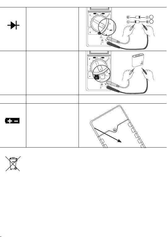
Diode
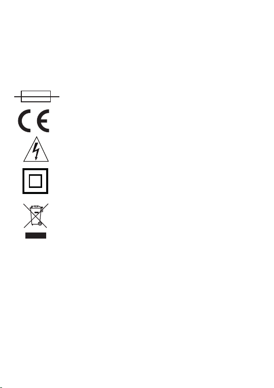
Remplacement des piles :
Batterie faible
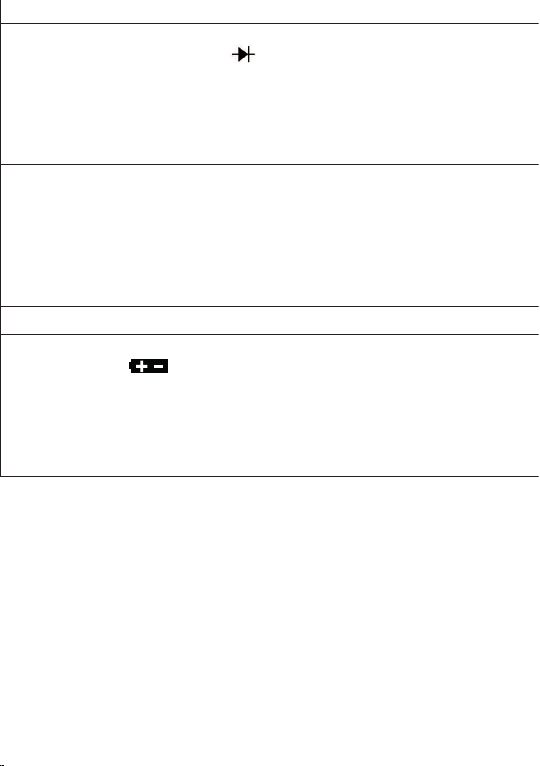
hFE
Transistor
200
20
2000
m
200m
250
250 250
200
2000
µ
20m 200
2000
20k
200k
2000k
10A
Ω
VV
A
OFF
10A
~
MAX 10 sec
EACH 15 min
FUSED
COM
VΩmA
!
200m
hFE
hFE
250V
200mA
FUSED MAX
~
200
2000
20k
cathode (-)
anode (+)
A
B
200
20
2000
m
200m
250
250 250
200
2000
µ
20m 200
2000
20k
200k
2000k
10A
Ω
VV
A
OFF
10A
~
MAX 10 sec
EACH 15 min
FUSED
COM
VΩmA
!
200m
hFE
hFE
250V
200mA
FUSED MAX
~
200
10A
10A
MAX10 sec
hFE
7
Quand le symbole apparaît, vous devez remplacer les piles.
1. Mettez le sélecteur sur Off
2. Dévissez la vis à l’arrière du testeur
3.
Ouvrez et remplacez les 2 piles par des piles de même type (2xLR03 1,5V)
4. Revissez.
Le remplacement du ou des fusibles est très rarement nécessaire et s’effectue généra-
lement à la suite d’une erreur de manipulation, remplacez-les par des fusibles de même
modèle en suivant la même procédure que pour le remplacement des piles.
1. Reliez la sonde noire à la borne COM et la sonde rouge à la borne VΩmA
2. Mettez le commutateur de fonction sur la position
3. Connectez les pointes test sur la diode :
(A) test dans le sens direct : connectez la pointe noire sur la cathode et la pointe rouge sur
l’anode, en mesurant la tension dans le sens passant d’une diode normale, l’écran indiquera
entre 0,5 et 0,7V et le sens bloqué indiquera «1»,
(B) test dans le sens inverse : connectez la pointe noire sur l’anode et la pointe rouge sur la
cathode. La diode est bonne si l’écran indique «1».
1. Reliez la sonde noire à la borne COM et la sonde rouge à la borne VΩmA
2. Mettez le commutateur de fonctions sur la position hFE
3. Connectez la pointe noire dans la borne COM de l’adaptateur et la pointe rouge dans
l’autre borne, connectez ensuite le transistor dans les trous appropriés de l’adaptateur
selon le type du transistor NPN ou PNP
4. Lisez la valeur indiquée à l’écran quand elle est stabilisée (gain en courant).
8
Modèle n°DT830D
- Indication de dépassement : afchage “OL” (Over Limit)
- 2 fusibles de protection : 200mA 250V - 10A 250V
- Températures pour le fonctionnement : 0°C~40°C
- Températures de stockage : -10°C~ 50°C
- Dimensions et Poids : 27x70x126mm / 120gr (avec les piles)
- Niveau de sécurité : CAT III.
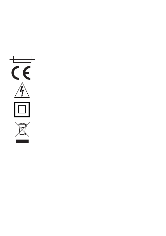
Protégé par fusible standard
Certié conforme aux normes européennes
Risques résultants de tensions dangereuses
Classe II : matériel double isolation, dispensé
de raccord à la terre
Les produits électriques usagés ne doivent pas être
jetés avec les ordures ménagères. Veuillez utiliser
les aménagements spécifiques prévus pour les traiter.
TIBELEC GARANTIT LA QUALITE ET LA FIABILITE DE CE PRODUIT ; IL FAIT PARTIE
DES ARTICLES SOUS GARANTIE LEGALE D’UNE DUREE DE 2 ANS POUR DEFAUTS
ET VICES CACHES CONFORMEMENT AUX ARTICLES 1641
A 1648 DU CODE CIVIL.
Tibelec ne pourra pas être tenu responsable des dommages causés suite à une
mauvaise utilisation, mauvais entretien, un détournement de l’utilisation de ce produit,
l’usure normale, bris par chute, ouverture de l’appareil. Tibelec ne pourra pas accepter
en retour les produits pour remplacement des consommables (lampes, transfo., verre)
nécessaires à l’utilisation de ce produit. Le remplacement des consommables est à
votre charge.
Importé par tibelec 996 rue des hauts de Sainghin CRT4
59262 Sainghin en Mélantois - France

9

10
Warning :
1. Be particularly careful when using voltages above 30V AC (RMS) or 60V DC to avoid
damage or electric shock.
2. Never apply an input voltage higher than the maximum value of the range allowed by
the device manufacturer. This monitor is design for low voltage applications. (250V
MAX IN AC/DC)
3. Never use the tester to measure the line feeding a device that generates a sudden
surge in voltage as it may exceed the maximum permitted voltage (e. g. motors).
4. Never use the tester if the test plungers or leads are damaged or broken. Make sure
they are never wet or damp; check that the tester and the leads are working properly
before commissioning.
5. Opening the housing gives access to hazardous voltage conductive parts. Any action
on internal circuits could result in hazardous use. Never use the disassembled tester.
Before using it: check that the housing is properly closed and screwed in.
6. Always make sure your ngers are behind the test plunger guard during measure
ments. During the measurement, be careful not to come into direct or indirect
contact (e. g. with ngers) with high voltage conductive parts.
7. Be sure to disconnect the plungers of the leads from any voltage source and the
circuit to be measured; remove the plungers when changing function. Before perfor
ming any work (e. g. changing batteries) or before turning the rotary switch to change
functions, disconnect the tester.
8. Before taking a measurement, make sure the function selector switch is in the correct
position.
IMPORTANT: these instructions are for your safety. Read
them carefully before use and keep them for future use.
GB

11
200
20
2000
m
200m
250
250 250
200
2000
µ
20m 200
2000
20k
200k
2000k
10A
Ω
VV
A
OFF
10A
~
MAX 10 sec
EACH 15 min
FUSED
COM
VΩmA
!
200m
hFE
hFE
250V
200mA
FUSED MAX
~
1
2
3
1. LCD display
2. Function switch
3. Jack 10A red test leads
4. Jack VΩmA red test leads
5. Jack COM black test leads
6. Batteries compartment
4
5
• LCD display, max 1999-digit reading
• Function switch : Voltmeter AC, Ohmmeter, diode test, Continuity with
buzzer, hFE transistor, Ammeter DC, Voltmeter DC.

12
AC voltage
0 to 250V
Use :
DC voltage
0 to 250V
Direct current DC
0 to 10A
Resistance
(Ohmmeter
0 to 20MΩ
Continuity with buzzer
V
DCV
V~
ACV
Ω
A
+
-
200
20
2000
m
200m
250
250 250
200
2000
µ
20m 200
2000
20k
200k
2000k
10A
Ω
VV
A
OFF
10A
~
MAX 10 sec
EACH 15 min
FUSED
COM
VΩmA
!
200m
hFE
hFE
250V
200mA
FUSED MAX
~
200
20
00
m
250
O
200
20
2000
m
200m
250
250 250
200
2000
µ
20m 200
2000
20k
200k
2000k
10A
Ω
VV
A
OFF
10A
~
MAX 10 sec
EACH 15 min
FUSED
COM
VΩmA
!
200m
hFE
hFE
250V
200mA
FUSED MAX
~
250
250
200
V
OFF
+
-
batterie
200
20
2000
m
200m
250
250 250
200
2000
µ
20m 200
2000
20k
200k
2000k
10A
Ω
VV
A
OFF
10A
~
MAX 10 sec
EACH 15 min
FUSED
COM
VΩmA
!
200m
hFE
hFE
250V
200mA
FUSED MAX
~
20m
10A
200m
200
20
2000
m
200m
250
250 250
200
2000
µ
20m 200
2000
20k
200k
2000k
10A
Ω
VV
A
OFF
10A
~
MAX 10 sec
EACH 15 min
FUSED
COM
VΩmA
!
200m
hFE
hFE
250V
200mA
FUSED MAX
~
200
200k
2000k
Ω
200
20
2000
m
200m
250
250 250
200
2000
µ
20m 200
2000
20k
200k
2000k
10A
Ω
VV
A
OFF
10A
~
MAX 10 sec
EACH 15 min
FUSED
COM
VΩmA
!
200m
hFE
hFE
250V
200mA
FUSED MAX
~
200
200
20
A
hFE

13
1. Connect the black probe to terminal COM and the red probe to terminal VΩmA
2. Set the function switch to the desired DC voltage rating
3. Connect the test plungers to the circuit and read the value displayed on screen once
it has stabilised. When measuring DC voltage, the display shows the polarity of the
red probe.
1. Connect the black probe to terminal COM and the red probe to terminal VΩmA
2. Set the function switch to the desired AC voltage rating
3. Connect the test plungers to the circuit and read the value displayed on screen once
it has stabilised.
1. Connect the black probe to terminal COM and the red probe :
to terminal VΩmA if measure <200mA
to terminal 10A if measure <10A and > 200mA
2. Set the function switch to the desired DC direct current rating
3. Connect the test plungers to the circuit and read the value displayed on screen once
it has stabilised.
1. Connect the black probe to terminal COM and the red probe to terminal VΩmA
2. Set the function switch to the desired resistance rating
3. Connect the test plungers to the circuit and read the value displayed on screen once
it has stabilised.
1. Connect the black probe to terminal COM and the red probe to terminal VΩmA
2. Set the function switch to position
3. The buzzer will sound if the resistance is ≤30Ω.
14
Low battery
The consumer is obliged by law to recycle all used batteries and accumulators. It is forbid-
den to throw them in the ordinary bin! Refer to the environmental protection details.
Diode
Transistor
hFE
200
20
2000
m
200m
250
250 250
200
2000
µ
20m 200
2000
20k
200k
2000k
10A
Ω
VV
A
OFF
10A
~
MAX 10 sec
EACH 15 min
FUSED
COM
VΩmA
!
200m
hFE
hFE
250V
200mA
FUSED MAX
~
200
2000
20k
cathode (-)
anode (+)
A
B
200
20
2000
m
200m
250
250 250
200
2000
µ
20m 200
2000
20k
200k
2000k
10A
Ω
VV
A
OFF
10A
~
MAX 10 sec
EACH 15 min
FUSED
COM
VΩmA
!
200m
hFE
hFE
250V
200mA
FUSED MAX
~
200
10A
10A
MAX10 sec
hFE
15
The replacement of the fuse is very rarely necessary and is usually due to a
handling error; replace it with fuses of the same model.
When the symbol appears, you must replace the batteries.
1. Set the selector switch to Off
2. Loosen the screw on the back of the tester
3.
Open and replace the batteries with batteries of the same type (2xLR03 1,5V)
4. Tighten again.
1.
Connect the black probe to terminal COM and the red probe to terminal VΩmA
2.
Set the function switch to position
3. Connect the test plungers to the diode :
(A) test in the direct direction: connect the black plunger to the cathode and the
red plunger to the anode, measuring the voltage in the direction of a normal
diode; the screen will display 0.5 to 0.7V and the blocked direction will display “1”
(B) test in the opposite direction: connect the black plunger to the anode and the
red plunger to the cathode. The diode is good if the display shows “1”.
1.
Connect the black probe to terminal COM and the red probe to terminal VΩmA
2. Set the function switch to position hFE
3. Connect the black plunger to the COM terminal of the adapter and the
red plunger to the other terminal, then connect the transistor to the
appropriate holes in the adapter depending on the type of NPN or PNP
transistor (current gain).
4. Read the value displayed on screen once it has stabilised (current gain).
16
Protected by standard fuse
Certied in accordance with European standards
Risks resulting from hazardous voltages
Class II equipment without ground connection
Do not dispose of appliances bearing this symbol with
domestic waste. Use a suitable collection point.
Tibelec guarantees the quality and reliability of this product’s components: this item is
legally required to be accompanied by a 2-year warranty for aws and latent defects
in accordance with articles 1641 to 1648 of the Civil Code. Our technical support
service is available for advice and assistance; please contact us at [email protected].
Tibelec cannot be held liable for damage caused by incorrect use, poor maintenance,
misuse of the product, normal wear and tear, damage from falls, or opening of the
xture. Tibelec cannot accept returns for replacement of the consumable items (bulbs,
transformers, glass, etc.) that are required for the use of this product. The replacement
of consumable items is your responsibility.
Model n°DT830D
- Exceedance indication: “OL” (Over Limit) displayed
- 2 protection fuses : 200mA 250V - 10A 250V
- Operating temperature : 0°C~40°C
- Storage temperature : -10°C~ 50°C
- Size and Weight : 27x70x126mm / 120gr (with batteries)
- Safety standard : CAT III.
Imported by Tibelec 996 rue des hauts de Sainghin CRT4
59262 Sainghin en Mélantois - France

17

18
ES
Advertencia :
1. Tenga especial cuidado cuando utilice tensiones superiores a 30 V CA (RMS)
o 60 V CC para evitar daños o descargas eléctricas.
2. Nunca aplique un valor de entrada superior al valor máximo del rango permitido
por el fabricante del dispositivo. Este controlador está diseñado para aplicaciones
de baja tensión. (250V MAX EN CA/CC)
3. No utilice nunca el aparato para medir la línea que alimenta un dispositivo que
genera una sobretensión, ya que puede superar la tensión máxima permitida
(p. ej., motores).
4. Nunca utilice el probador si las sondas de prueba o los cables de prueba están
dañados o rotos. Asegúrese de que no estén húmedos o mojados; compruebe
el correcto funcionamiento del probador y de los cables antes de ponerlos en
marcha.
5. La apertura de la carcasa da acceso a piezas conductoras de valores de tensión
peligrosos. Cualquier acción en los circuitos internos puede resultar en un uso
peligroso. Nunca utilice el probador desmontado. Antes de utilizarlo: compruebe
que la carcasa esté bien cerrada y atornillada.
6. Mantenga siempre los dedos detrás de la protección de la sonda de prueba
durante las medidas. Durante la medición, tener cuidado de no entrar en contacto
directo o indirecto (p. ej. con los dedos) con las piezas conductoras de alta ten
sión.
7. Asegúrese de desconectar las sondas de los cables de cualquier fuente de tensión
y del circuito que se va a medir, retire las sondas cuando cambien de función.
Antes de realizar cualquier trabajo (por ejemplo, cambiar las pilas) o antes de girar
el selector para cambiar las funciones, desconecte el aparato.
8. Antes de realizar una medición, asegúrese de que el selector de funciones
esté en la posición correcta.
IMPORTANTE: estas instrucciones son para su seguridad.
Léalas cuidadosamente antes de utilizar el aparato y
guárdelas para un futuro uso.

19
1. Pantalla LCD
2. Conmutador de funciones
3. Clavija 10A Cable rojo
4. Clavija VΩmA Cable rojo
5. Clavija COM Cable negro
6. Compartimento de las baterías
• Pantalla LCD, lectura máxima de 1999 dígitos
• Conmutador de funciones : Voltímetro alterna, Ohmímetro, prueba de
diodos, Continuidad con zumbador, hFE transistor, Amperímetro continuo,
Voltímetro continuo.
200
20
2000
m
200m
250
250 250
200
2000
µ
20m 200
2000
20k
200k
2000k
10A
Ω
VV
A
OFF
10A
~
MAX 10 sec
EACH 15 min
FUSED
COM
VΩmA
!
200m
hFE
hFE
250V
200mA
FUSED MAX
~
1
2
3
4
5

20
Tensión alterna
de 0 a 250V
Tensión continua
de 0 a 250V
Intensidad continua
de 0 a 10A
Resistencia
(Ohmímetro)
de 0 a 2MΩ
Uso :
Continuidad con
zumbador
V
DCV
V~
ACV
Ω
A
+
-
200
20
2000
m
200m
250
250 250
200
2000
µ
20m 200
2000
20k
200k
2000k
10A
Ω
VV
A
OFF
10A
~
MAX 10 sec
EACH 15 min
FUSED
COM
VΩmA
!
200m
hFE
hFE
250V
200mA
FUSED MAX
~
200
20
00
m
250
O
200
20
2000
m
200m
250
250 250
200
2000
µ
20m 200
2000
20k
200k
2000k
10A
Ω
VV
A
OFF
10A
~
MAX 10 sec
EACH 15 min
FUSED
COM
VΩmA
!
200m
hFE
hFE
250V
200mA
FUSED MAX
~
250
250
200
V
OFF
+
-
batterie
200
20
2000
m
200m
250
250 250
200
2000
µ
20m 200
2000
20k
200k
2000k
10A
Ω
VV
A
OFF
10A
~
MAX 10 sec
EACH 15 min
FUSED
COM
VΩmA
!
200m
hFE
hFE
250V
200mA
FUSED MAX
~
20m
10A
200m
200
20
2000
m
200m
250
250 250
200
2000
µ
20m 200
2000
20k
200k
2000k
10A
Ω
VV
A
OFF
10A
~
MAX 10 sec
EACH 15 min
FUSED
COM
VΩmA
!
200m
hFE
hFE
250V
200mA
FUSED MAX
~
200
200k
2000k
Ω
200
20
2000
m
200m
250
250 250
200
2000
µ
20m 200
2000
20k
200k
2000k
10A
Ω
VV
A
OFF
10A
~
MAX 10 sec
EACH 15 min
FUSED
COM
VΩmA
!
200m
hFE
hFE
250V
200mA
FUSED MAX
~
200
200
20
A
hFE
This manual suits for next models
1
Table of contents
Languages:
Other tibelec Test Equipment manuals


Popular Test Equipment manuals by other brands

RuiDeng
RuiDeng UM24 instructions

PCE Health and Fitness
PCE Health and Fitness PCE-COM 20 user manual

Atlanta
Atlanta ASF-2050 COMBO user manual

Reed Instruments
Reed Instruments TM-8811 instruction manual

Rohde & Schwarz
Rohde & Schwarz CTS60 operating manual

ACE INSTRUMENTS
ACE INSTRUMENTS AL5500 plus quick start guide


