Tidel TACC-IIa User manual

TACC-IIa
Problem Identifi cation
By Component

6
General Information
When there is a problem of any nature with the TACC unit, perform a power reset, then
attempt the function again. A power reset can be performed by removing and reinserting
the fuse or the AC power cord.
Whenever a corrective action has been performed, a power reset should be performed
prior to attempting the function again.
Whenever a
power reset is performed, all LED’s should illuminate momentarily (LED
test).
Always have the Serial number of the unit readily available when performing service,
contacting the Tidel Help Desk for assistance, placing parts orders or when requesting
warranty information/processing.
Serial Number information
A91-XXXXX
TACC-IIa, (Built in 1991)
Changes made from TACC-IIR to TACC-IIa:
Display was removed from Control Panel.
All locks moved to front service positions (except vend tube lock).
Door motor assembly was eliminated.
Door Sensor is unique to this year only.
Vend tube lock bar “built in” to prevent loss.
The Main PCB is different from TACC-IIR.
Did not change from TACC-IIR to TACC-IIa:
Equipped with a Lower Sensor PCB.
Uses same Dipstick, Cradles, Tubes, Motors and Timing Disks as TACC-IIR.
A92-XXXXX
TACC-IIa, (Built in 1992)
Changes made from A91 to A92:
Power Supply mounting moved from the magazine to the top/inside of cabinet.
Lower Sensor PCB was eliminated.
Sensors are mounted directly on magazine back-
plate.
Timing Disk changed to accommodate the absence of the Lower Sensor PCB.
Door Sensor is different from A91 and TACC-IIR.
Main PCB changed to incorporate the Lower Sensor PCB circuitry.
Did not change from A91 to A92:
Uses same Dipstick, Cradles, Tubes, Motors and Timing Disks as A91 and TACC-IIR.
A93-XXXXX
TACC-IIa (Built in 1993)
No changes were made from A92 to A93
Problem Identifi cation By Component

7
IA-XXXXX
TACC-IIa - Production began 1994
The diameter of the Vend Tubes were increased to accomodate international coins.
Due to the increased size of the tubes, the capacity of the magazine decreased from
12 tubes per column (all units prior to this serial number), to 11 tubes per column.
In addition, the Magazine, Vend Tubes and Dipsticks are different from all units manu-
factured prior to this serial number.
IA-15550
and above (approximately) - ADA height requirement cabinets began production.
2 inches were removed from the height of the cabinet and 2 inches were added
to the depth of the cabinet to compensate.
Door drill point is 2 inches lower than Non-ADA height requirement cabinets
(see Specifi cations in the installation section of this manual).
Measurements for drilling the door to manually lift the Door Solenoid Plunger will
place the access point on the right side of Solenoid Plunger.
IA-24097 and above
(approximately) - Door Solenoid mounting bracket was moved.
The Solenoid mounting bracket moved approximately one inch toward the center
of the door.
Measurements for drilling the door to manually lift the Door Solenoid Plunger will
place the access point on the left side of Solenoid Plunger.
IA-29420 and above
- Units were equipped with a redesigned Main PCB.
The new Main PCB is backward compatible with older units.
Door delay opening times to be selected by setting the SW1 dipswitches.
To stop the “tube dump” feature, the Vending Keyswitch must be turned to the
OFF position.
IL-XXXXX
TACC-IIa with rear door.
This unit was equipped with a door on the front and rear of the unit. The solenoid was
mounted on the rear door. After the rear door was opened, a release pin allowed the
front door to be opened fron the rear.
On units equipped with rear doors, the Manager Keyswitch is mounted in the upper,
right hand corner of the cabinet.
On units with rear doors, the Vend Tube Lock Bar Lock is mounted in the left hand
corner of the cabinet.
For through the wall applications.
IN-XXXXX
TACC-IIa built for overseas applications (Thailand)
SA-XXXXX
TACC-IIa redesign for Sentinel cabinet design. Production began late 2006.
The Control Panel Chassis size increased to be interchangeable with Sentinel, TACC-V
and TACC-III cabinets (This Control Panel is not interchangeable with earlier units).
Door opens in opposite direction (Hinges mounted on left side).
Measurements for drilling the door to manually lift the Door Solenoid Plunger will place
the access point on the right side of Solenoid Plunger.
Vend Tube Loading Gate key moved to left hand corner of unit.
The size of the back wall on the unit was reduced by approximately half. Only (2) 3/4”
nuts secure the back wall in place.
Problem Identifi cation By Component

8
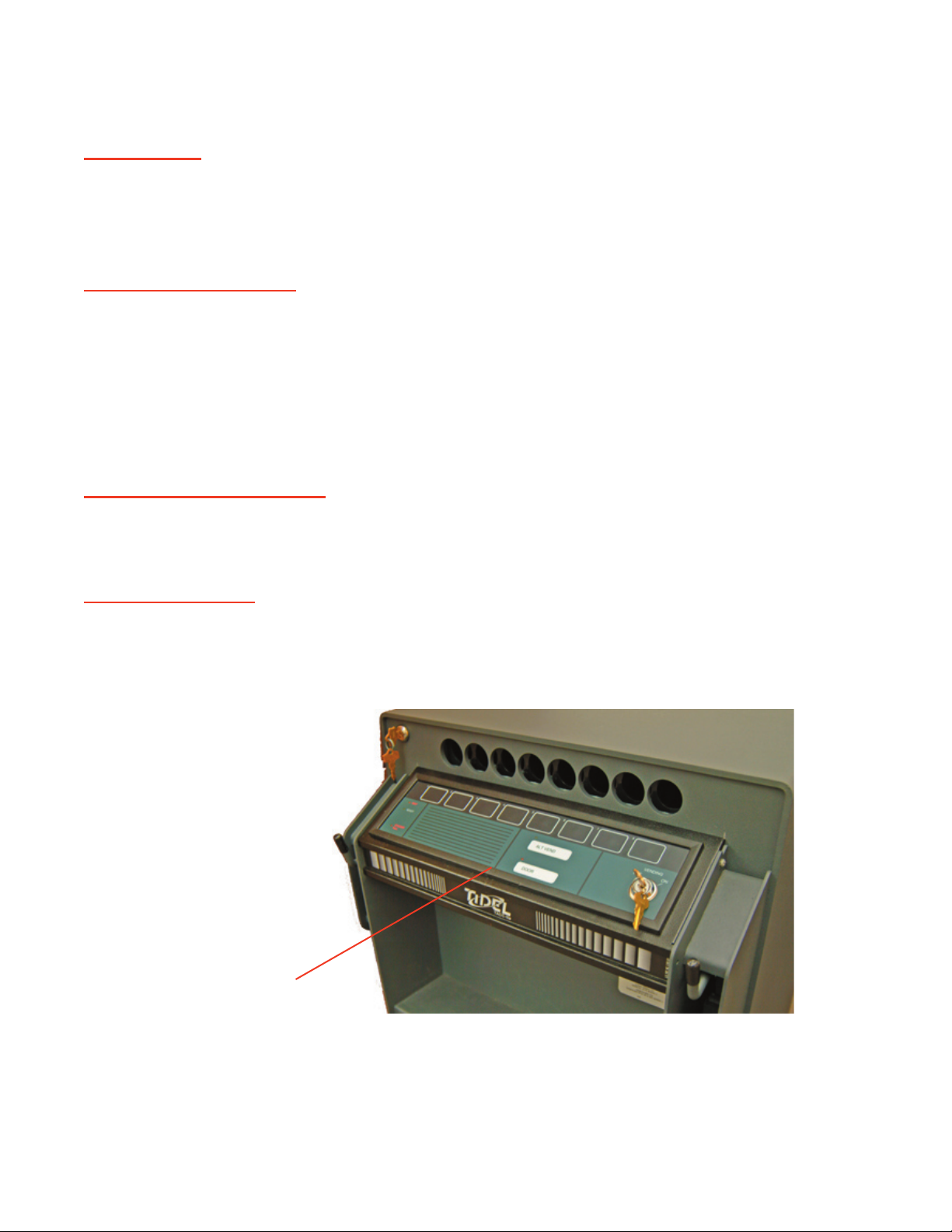
Control Panel
For information on the Vending Keyswitch, see “Keyswitches” in this section.
Units with Serial # beginning with “SA” have a Control Panel chassis that is not interchangeable
with serial #’s beginning with “IA, A93, A92 or A91”.
The Control Panel basically is a
Touchpad consisting of 8 vend buttons, the
door button, the Alt
Vend button and 5 indicator
LED’s, (
Wait,
Ready,
Alt Vend,
Door and
Stacker Full).
Each “pair” of
vend buttons on the Control Panel operate 1 vend motor.
There a 4 vend motors. Each motor turns a cradle back and forth to dispense tubes from two
columns in the magazine.
Much information can be gained by vending a tube.
Make sure the green READY light is illuminated and note the following:
a) When a vend button is pressed, the Control Panel LED’s give you a response, (an
LED will illuminate or go out).
This is an indication that the unit “saw” you press the button. The button and
rib-
bon cable connection to the Main PCB are functional.
b) The vend motor operates, (turns back and forth to vend a tube). This confi rms
that the vend motor is operable and the power supply is functional, (lights and
motors are functioning).
c) The cradle turns, allows a tube to drop into the cradle, the cradle reverses direc-
tion and drops the tube through the front of the unit. This confi rms the cradle
and gears are intact and the sensors are functional.
It is important that you verify that a response is given by the Control Panel when
the button is pressed.
If no response is indicated when the vend button is pressed, (the LED’s do not re-
spond), the unit does not “see” the button.
The “STACKER FULL” LED is not used by the TACC-IIa.
Door timer or Alternate Vend timer will not start
The Alternate Vend delay timer cannot be started if the unit “sees” the door in the un-
locked position.
The problem may be related to the button or the Manager Keyswitch.
To isolate the problem, perform the following test:
Turn the
Manager key and release it.
Press the Door button.
If the DOOR light does not illuminate, quickly press the Alt Vend button.
a) If the ALT VEND light illuminates, the Manager Keyswitch is functional. The DOOR
light or the Door button on the Control Panel may be defective.
b) If the ALT VEND light will not illuminate, the problem may be related to the Man-
ager Keyswitch.
1)
2)
3)
Contnued on next page
Contnued on next page
Problem Identifi cation By Component
9
Control Panel (continued)
Drink spills
Check the backside of the Control Panel for evidence of spills.
Drink spills on the Control Panel wont affect other components inside the unit. Damage is usu-
ally limited to the Control Panel.
Drinks spills can cause a range of problems from
inoperative buttons to defective LED’s.
Worn/stuck buttons
Look for obvious signs of abuse/wear.
If a vend button is stuck, all buttons will become inoperable (no response).
If a vend button is non-functional, all other buttons should operate.
If all vend buttons are inoperable, (no response), disconnect and reconnect the
ribbon cable,
which connects the Touchpad to the Main PCB, while power is applied to the unit and the ready
light is illuminated.
If the unit vends a tube, the button for the column vended is stuck .
LED’s do not illuminate
When AC power is applied to the unit, all LED’s should illuminate momentarily.
If the Ribbon Cable is connected to the Control Panel upside down, no components will be dam-
aged, but no LED’s will illuminate and no button will work.
Static Discharge
Static discharge can cause damage to components on the TACC-IIa
Insure grounds from the Control Panel to cabinet are present on unit.
Problem Identifi cation By Component
Control Panel

10
Doors
Sprung Door
The door tends to push outward. Customers usually report they have to push in on the door to
turn the door bolt key.
Fold a piece of paper as many times as possible, then place it between door and door
frame on the hinge side. Close the door against the folded paper to pull the hinges out.
Sagging Door
Door hangs at an angle.
Remove the door from hinges.
Using a block of wood, gently tap top hinge away from center of unit and tap lower
hinge toward center of unit.
Perform this procedure a little at a time, replacing the door to check the fi t often.
Worn Hinges
Remove the door and add shims to the hinge pins.
Note:
Lubricate the shims and hinges.
1)
2)
3)
Problem Identifi cation By Component
11
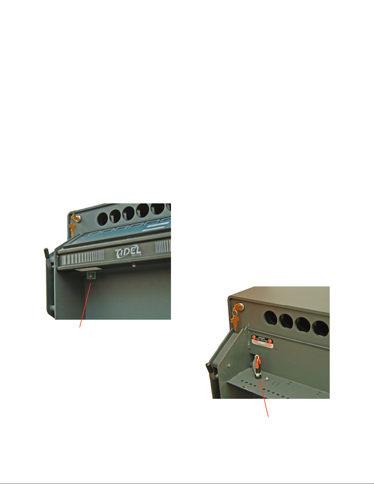
Fuse
The fuse is located under the Control Panel, next to the serial # sticker.
All TACC units use a
1 amp slow-blow fuse.
Common areas to check:
Fuse Holder cracked or broken.
Fuse holder wires frayed or broken from twisting fuse holder.
Fuse cable wires incorrectly connected to the Power Supply terminal strip.
Incorrect fuse size/amp rating.
When AC power is applied to the unit, a faint “click” from the
Power Supply should be heard.
This “click” indicates AC power is being applied to the Power Supply. This indicates
AC power
is present at the power source (wall socket), the Fuse is not blown and the
Fuse Cable has a
complete circuit.
If the click is heard, but no lights illuminate on power up, the Ribbon Cable on
the Control Panel may be connected upside down.
If no click is heard, the Fuse, Fuse Holder, Fuse cable, Power Cord and VAC
source (wall socket) should be checked.
Problem Identifi cation By Component
Fuse Cap
Fuse Holder Assy

12
Keyswitches
Keyswitch (Courier/Instant Access)
The Instant Access Keyswitch is mounted below the Manager Keyswitch on the door.
The Keyswitch is spring loaded and should return to the off position when released.
The Keyswitch is supplied with 4 keys and an aluminum tag which has a
key code im-
printed on it.
The Keyswitch is a restricted keyway. Replacement keys cannot be made locally. The key
code must be supplied to Tidel and only then can Tidel supply replacement keys.
The
Instant Access
Keyswitch wiring is connected to the COMMON and NORMALLY OPEN termi-
nals of the Keyswitch.
To open the door using the Instant Access Keyswitch, turn the Instant Access Keyswitch ON and
release it and turn the door bolt key. (Single key operation).
Some units are setup for “
Dual Function” key operations. Dual Function units require the follow-
ing to open the door:
Turn the Instant Access key and release it.
Turn the
Manager key within 30 seconds.
Turn the Door bolt key.
Instant Access Key Operation Options:
Single Key:
(Courier Key is turned, the solenoid activates immediately)
SW-4 = OFF
Dual Function:
(Courier Key must be turned 1
st
, the Time Delay key must be turned 2
nd
, then the solenoid will
activate)
Keyswitch (Dispensing/Vending)
The
Vending Keyswitch is located on the Control Panel and controls the vending operations only.
When the Vending Keyswitch is in the OFF position:
The
wait light will remain on and no vends are possible.
The Vend Delay timer will continue to advance.
If the Vending keyswitch is in the ON position and the
ready light will not illuminate:
Insure the 2 minute vend delay time has been achieved.
Insure the Door is shut and locked, (door light is not illuminated).
Disconnect the Vending Keyswitch from the 2-pin header on the back of the Control
Panel.
Jumper the 2-pin header on the Control Panel.
a) If the READY light illuminates, the Vending Keyswitch or associated wiring may be
defective.
b) If the READY light does not illuminate, the problem may be related to the Control
Panel or Ribbon Cable.
1)
2)
3)
1)
2)
3)
4)
Problem Identifi cation By Component
Contnued on next page
Contnued on next page
13
Keyswitches
Keyswitch (Manager/Time Delay)
The Keyswitch is spring loaded and should return to the off position when released.
The Keyswitch is supplied with 4 keys and an aluminum tag which has a
key code im-
printed on it.
The Keyswitch is a restricted keyway. Replacement keys cannot be made locally. The key
code must be supplied to Tidel and only then can Tidel supply replacement keys.
Note:
Replacement keys can be made from an existing key but de-coding fees will apply.
To start the Door opening delay timer, turn the Manager Keyswitch and release it, then press
the door button on the Control Panel within 30 seconds.
Note:
A91 series units did not require
pressing the
door button on the Control Panel.
The
DOOR light should illuminate momentarily.
If the Door timer, (or Alternate Vend timer), will not start, the problem may be related to the
button on the Control Panel or the Manager Keyswitch.
To isolate the problem, perform the following test:
Turn the Manager key and release it.
Press the Door button.
If the DOOR light does not illuminate, quickly press the Alt Vend button.
a) If the
ALT VEND light illuminates, the Manager Keyswitch is functional. The DOOR
light or the Door button on the Control Panel may be defective.
b) If the
ALT VEND light will not illuminate, the problem may be related to the Man-
ager Keyswitch.
If the Keyswitch is going to be replaced, (due to lost keys, inoperative, etc), the front of the
Keyswitch can be cut off and the body of the lock pushed into the unit. The wires for the Key-
switch can be fi shed back through the hole in the door and momentarily touched together to
start the timer.
The Manager
Keyswitch wiring is connected to the COMMON and NORMALLY OPEN terminals of
the Keyswitch.
Do not attempt to convert the
Manager Keyswitch to an
Instant Access Keyswitch by moving
the Keyswitch connector from the MGR terminal, (J14), to the CRR terminal, (J15), on the Main
PCB.
The 30-second Alternate Vend feature cannot be activated if no keyswitch is connected to to the
MGR terminal (J6).
1)
2)
3)
Problem Identifi cation By Component
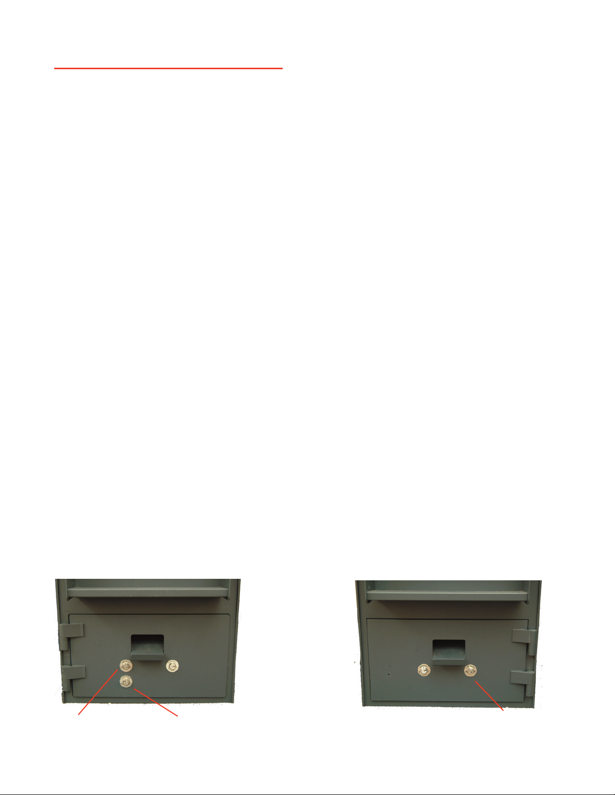
Current Production Door with
hinges on the left
Old Style Door with hinges
on the right
Manager/Time Delay
Keyswitch
Manager/Time Delay
Keyswitch
Instant Access/Courier
Keyswitch
14
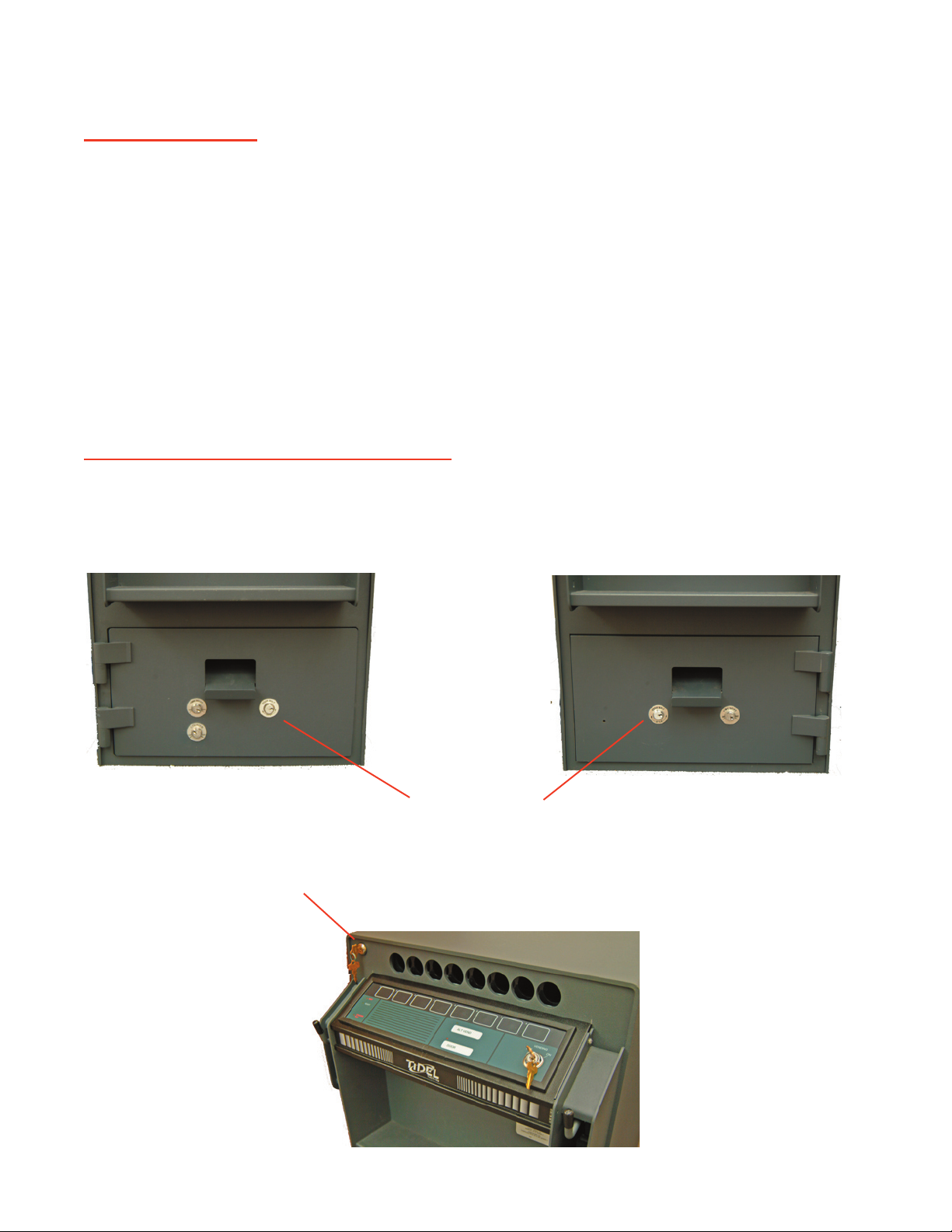
Locks
Lock (Door Bolt)
The
Door Bolt Lock is used to move the door locking bolt to the unlocked position.
The Door Bolt Lock is supplied with 2 keys and an aluminum tag, which has a key code,
imprinted on it.
The Door Bolt Lock is a restricted keyway. Replacement keys cannot be made locally.
The key code must be supplied to Tidel and only then can Tidel supply replacement keys.
Note:
Replacement keys can be made from an existing key but de-coding fees will apply.
The Door Bolt Lock operates the door locking bar by means of a cam.
If Door Bolt key is hard to turn, or requires rattling the door to operate, bend the tang of the
cam where it engages the
door locking bar.
If the lock is going to be replaced, (due to lost keys, inoperative, etc), the front of the lock can
be cut off and the body of the lock pushed into the unit. The door locking bar can be reached
though the hole left in the door.
Lock (Tube Loading Gate Lock Bar)
The Tube Loading Gate Lock lock is located in the top right corner of the unit.
If the Tube Loading Gate Lock is turned but does not operate the tube loading “Gate”, the
screw, which secures the cam to the lock, may have come loose or fallen out.
Problem Identifi cation By Component
Door Bolt Lock
Tube Loading Gate Lock

15
Magazine
Tubes or rolls of
coins jammed in the magazine can usually be dislodged from the bottom of the
magazine by performing the following:
With the door open, attempt to vend from the jammed column.
When the cradle is in the ½ way position, remove AC power from the unit.
From the bottom of the magazine, insert a ruler (or equivalent), into the column to
dislodge the tube.
Note:
Trying to force a tube down from the top of the magazine usually will make the jam
worse.
If jams are re-occurring, inspect the inside of the magazine for burrs, scratches or foreign ma-
terial such as glue, drink spills, etc…
1)
2)
3)
Problem Identifi cation By Component
Magazine
16
PCB, Main
The Main PCB controls all functions of the TACC-IIa.
The Main PCB houses the Service Diagnostic Switch and the
SW1 switch box (A92 and later se-
rial numbers).
The
Service Diagnostic Switch is useful in confi rming diagnosis of problems.
(See Service Diagnostic Switch section of this manual).
SW1 Switchbox
SW1 Switchbox
(Serial #’s
IA-29420 and above or units equipped with
Main PCB part # 201-5830-002S).
The
Optional Door Opening Delay Times and Key Operations are set by setting the SW-1
Switchbox
dipswitches for the desired operation:
Door Opening Delay Options:
3 minute delay 10 minute delay 30 minute delay
3 minute delay 10 minute delay 30 minute delay
SW-1 = OFF SW-1 = OFF SW-1 = OFF
SW-2 = ON SW-2 = OFF SW-2 = OFF
SW-3 = OFF SW-3 = OFF SW-3 = ON
Instant Access Key Operation Options:
Single Key:
(Courier Key is turned, the solenoid activates immediately)
SW-4 = OFF
Dual Function:
(Courier Key must be turned 1
st
, the Time Delay key must be turned 2
nd
, then the solenoid will
activate)
SW-4 = ON
Problem Identifi cation By Component
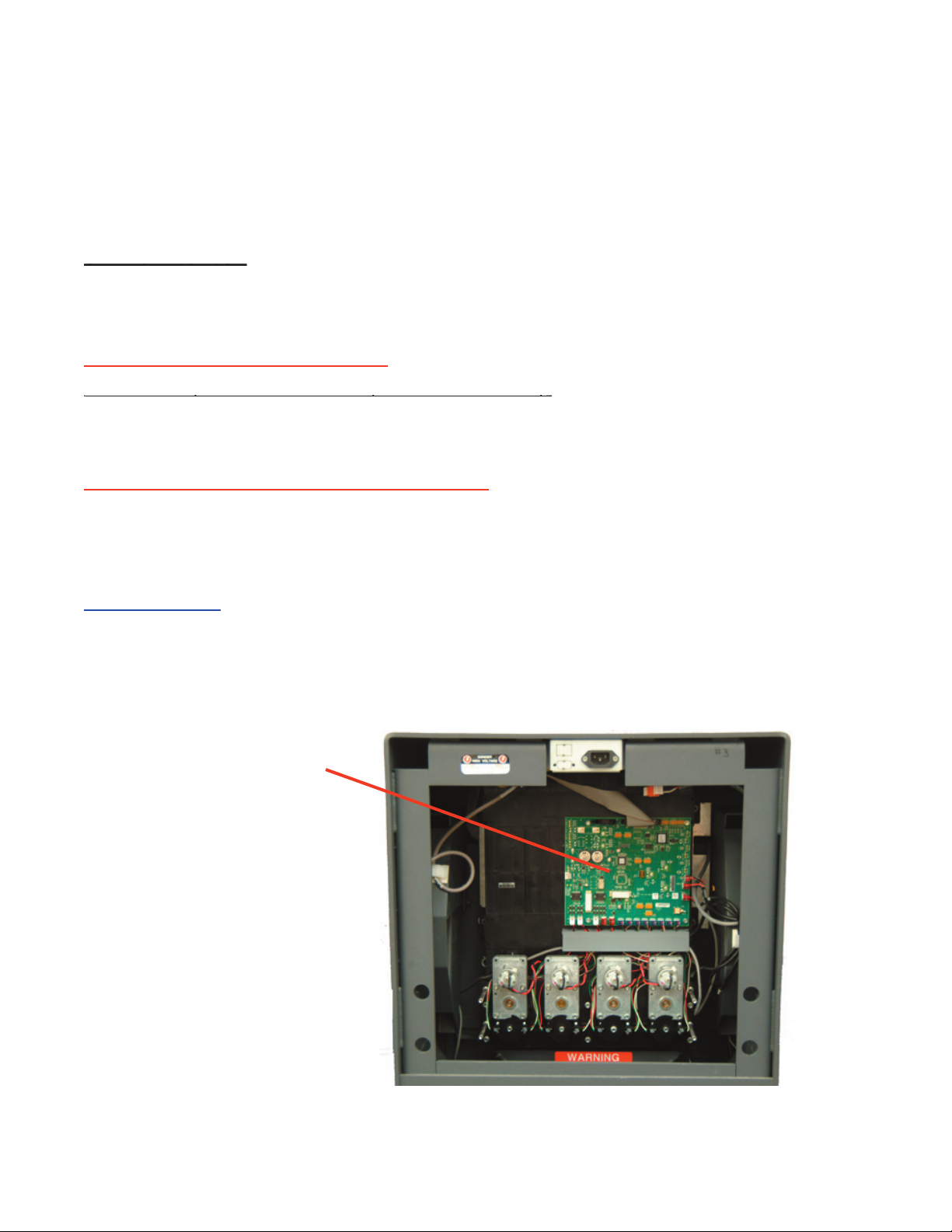
Main PCB

17
PCB, Motor Controller:
Only TACC-IIa’s with serial numbers beginning with A91 were equipped with Motor Controller
PCB’s.
In 1992, Motor Controller PCB’s were eliminated from the TACC product line.
The Motr Controller PCB controls the motor and vending functions.
The vending function of a TACC is performed by the following:
The vend motor drives the cradle back and forth to dispense tubes from the magazine.
A timing disk is attached to the stem of the cradle and rotates between 2 sensors, (1
at top and 1 at bottom), to determine the position of the cradle.
In the rest position, the top sensor is unblocked and the bottom sensor is blocked.
When a vend request is processed, the Motor Controller PCB energizes the motor.
As the motor drives the cradle, the timing disk rotates between the sensors.
When both sensors are seen open, the Motor Controller PCB stops the motor, reverses
the polarity, (therefore reversing the direction of the motor), and the motor runs again
until the top sensor is open and the bottom sensor is blocked.
The motor is back to it’s rest position and the tube falls out of the cradle.
A Vend Motor runs continuously
Typically a defective drive transistor, replace Motor Controller PCB.
Wait light fl ashes when a button is pressed
Anytime the unit detects a problem in the vending process, WAIT light on the Control Panel will
fl ash when the vend button is pressed.
To diagnose Motor Controller PCB problems, perform a power reset and LISTEN for the follow-
ing:
The unit makes a loud popping noise or binds. Probable jam in the cradle area
The unit vends a tube, works properly afterward. Tube or coins were jammed.
A vend motor runs a long cycle. Possible stripped gear/broken cradle/timing disk. Check
the action of the cradle, while the motor is running:
a) Check for damage to the cradle.
b) Cradle does not rotate. Possible stripped gears on motor or cradle.
c) Cradle rotates in 1 direction for 7 seconds. Possible broken timing disk, dirty or
defective Sensor.
A Vend Motor does not run.
Possible defective motor or Motor Controller PCB. To isolate the defective component,
perform the following:
a) Connect the non-functional motor into a terminal for a working motor.
b) Press the button, which corresponds, to the working motor.
c) If the motor does not run, the motor is defective.
d) If the motor runs, the Lower Sensor PCB is defective.
1)
2)
3)
4)
5)
6)
7)
1)
Problem Identifi cation By Component
18
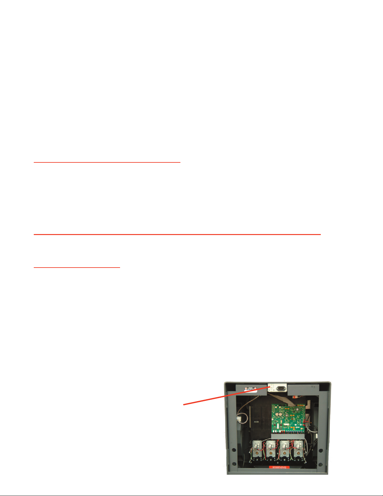
Power Supply
TACC-IIa units with serial #’s beginning with A91, had Power Supplies mounted on the maga-
zine assembly, covering the Main PCB.
All other TACC-IIa units had the Power supplies mounted to the top of the cabinet.
The Power Supplies are auto ranging and can be connected to 120vac or 240vac circuit without
modifi cations.
Units should be installed on an
isolated circuit or use the Tidel approved
surge suppressor.
Erratic or intermittent operation problems may be related to low output voltage from the Power
Supply.
The Power Supply converts incoming AC voltage to +12 and +5vdc.
+12vdc – operates the motors and door solenoid.
+5vdc - operates the Vend Senors, Door Sensor, logic circuits and LED’s.
No LED’s illuminate on the display
+5VDC failure. Upon
AC power up, a faint “click” should be heard coming from the
Power Supply. This indicates AC power is getting to the Power Supply.
If the click is heard, but no lights illuminate on power up, the Ribbon Cable on
the Control Panel may be connected upside down.
If no click is heard, the Fuse, Fuse Holder, Fuse cable, Power Cord and VAC
source (wall socket) should be checked.
No vend motors will operate and the door solenoid will not activate
+12VDC failure. No motors will operate. The WAIT light will fl ash when any vend but-
ton is pressed and the door locking bar solenoid will not operate.
Erratic LED behavior
If abnormal LED indications are observed, (example: WAIT and READY on at the same
time), check voltages at the
Power Supply output.
The
Output voltages of the Power Supply can be checked at J12 on the Main PCB.
RED = 5vdc
BLK = ground
WHT = 12vdc
If voltages are correct, the Main PCB may be cause of the problem.
If voltages are incorrect, the Power Supply may be defective or require +5VDC
adjustment.
1)
1)
1)
Problem Identifi cation By Component
Power Supply is mounted in
the top, inside of the cabinet
19
Power Supply Adjustment
WARNING:
Read the following completely BEFORE attempting to adjust the
+5vdc voltage.
Measure
voltage at terminal J12 on the Main PCB when making adjustments to the +5vdc.
When adjusting the +5vdc, the measurement at terminal J12 on the Main PCB must be between
+5.00~+5.10 vdc when the adjustment is fi nished.
See the Connection Layout section of this manual to reference the terminal and potentiometer
Turn the R31 Potentiometer VERY SLOWLY to raise or lower the output
voltage of the Power Supply.
Do not perform a voltage adjustment if the +5vdc output is correct!
Do Not adjust the voltage above +5.10vdc.
Do Not attempt to adjust the +12vdc, -12vdc or +24vdc if the +5vdc is
correct before making the adjustment.
Do Not apply pressure to the R31 potentiometer when adjusting. Dam-
age will occur.
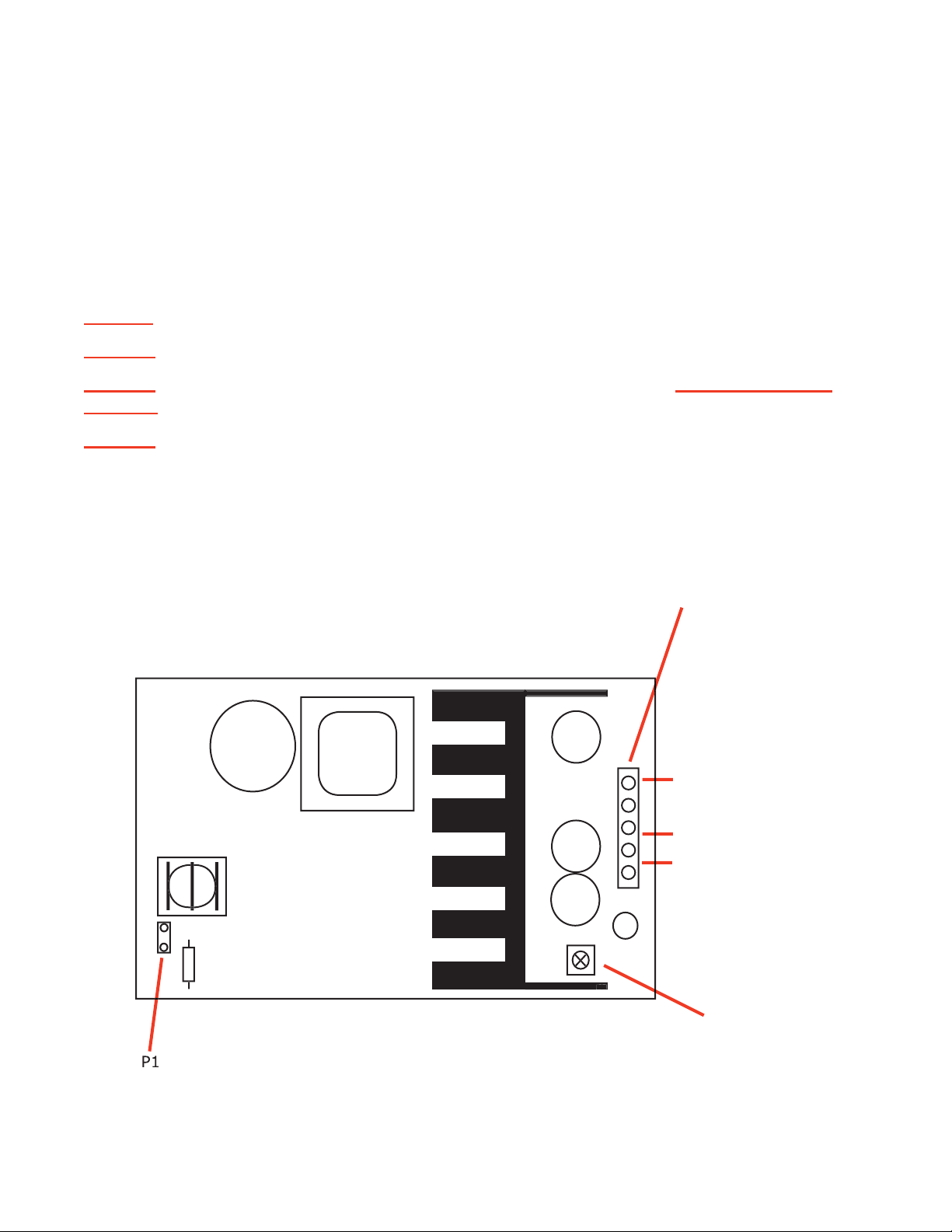
Problem Identifi cation By Component
P1
Incoming VAC power
from Fuse
R31-Poteniometer
+5 VDC adjust
P2-Power Supply Output
Wht = +12vdc
Red = +5vdc
BLK = Grnd
R31
F1
R31
R31
R31
R31
20
Sensors
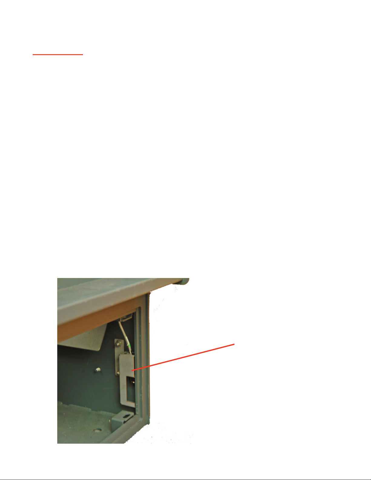
Door Sensor
The Door Sensor is located inside the unit, on the left side of the door frame.
Units with a serial # beginning with A91 have a different Door Sensor than all other TACC units.
Refer to the parts price list.
When the door locking bar engages the Door Sensor the
DOOR light will be off.
When the door locking bar is turned to the unlocked position, the DOOR light on the Control
Panel is illuminated.
If a customer complains of erratic door opening operations, the Door Sensor may be out of ad-
justment.
If the Door sensor is out of adjustment, you can usually shake door and see door light blink.
To adjust the Door Sensor, loosen the 2 screws at rear of bracket to and lower the
Door Sensor slightly.
DOOR light stays illuminated all the time
The Door Sensor may be broken or out of the bracket.
A visual inspection should reveal the problem.
If the Door Sensor appears to be properly secured in the bracket, operate the Door Sensor “fi n-
ger” manually and observe the DOOR light for a response.
a) If the DOOR light responds, the Door Sensor is probably out of adjustment.
b) If the DOOR light does not respond, the Door Sensor may be defective or discon-
nected from the Main PCB.
Warning:
Do not attempt to “splice” a replacement Door Sensor into the existing wiring har-
ness. Always replace the entire Door Sensor and cable.
Problem Identifi cation By Component
Door Bolt Sensor Mounting
21
Solenoid (Door)
The Door
Solenoid is operated by +12vdc.
Typically, when the solenoid energizes, a faint mechanical noise can be heard (the plunger be-
ing pulled into solenoid).
After the door opening delay time has expired, the DOOR light will illuminate on the Control
Panel. If the sound of the plunger being pulled in is not heard and the Door Bolt Key will not
operate, the solenoid may not be activating or the plunger may be bent.
Operation of the
plunger may be checked by simply moving the plunger up and down inside the
Solenoid.
If the plunger moves freely, the Solenoid or associated wiring may be the problem. The solenoid
can be checked by the following:
Connect the Solenoid to a known working Vend Motor terminal. Press the button corre-
sponding to the working Vend Motor terminal (Ready LED must be ON).
If the Solenoid operates, the Main PCB may be defective.
If the Solenoid does not operate, the Solenoid or associated wiring may be defec-
tive.
While the door is open (Door LED is ON), turn the Manager Key and release it. Within
30 seconds, check for +12vdc at the Solenoid quick-connect.
If voltage is present, the Solenoid may be defective.
If voltage is incorrect, the Main PCB or Power Supply may be defective (refer to
the Troubleshooting Guide in this manual).
1)
2)
Problem Identifi cation By Component
Door Solenoid
Door Bolt
Manager & Courier Keyswitches
Door Bolt Lock

22
Vending Components (Motors, Cradles and Timing Disks)
The gear on the Vend Motor shaft engages the gear on the Cradle to rotate the Cradles for
Vending
operations.
A Timing Disk is attached to the end of the Cradle post, which rotates through (2) Cradle Position
Sensors.
If the Vend motor runs but the Cradle doesn’t rotate, one of the
gears are usually stripped or
broken.
If the Vend motor runs a long cycle, but will not stop in the correct position, the Timing disk
may be broken or one of the Cradle Position Sensors may be dirty or defective.
To isolate the defective component, perform the following:
a) Perform a visual inspection of the Timing Disk.
b) Replace one of the Cradle Position Sensors. If the Porblem still exists, replace the other.
b) If the problem still exists, replace the Main PCB.
If a
Vend Motor will not run, the motor, Lower Sensor PCB, (A91 only), or Main PCB could be
defective.
To isolate the defective component, perform the following:
a) Connect the non-functional motor into a terminal for a working motor.
b) Press the button corresponding to the working motor.
c) If the motor does not run, the motor may be defective.
d) If the motor runs, the Lower Sensor PCB, (A91 only), or Main PCB may be defective.
A visual inspection of the Cradles and Timing Disks should reveal any defects.
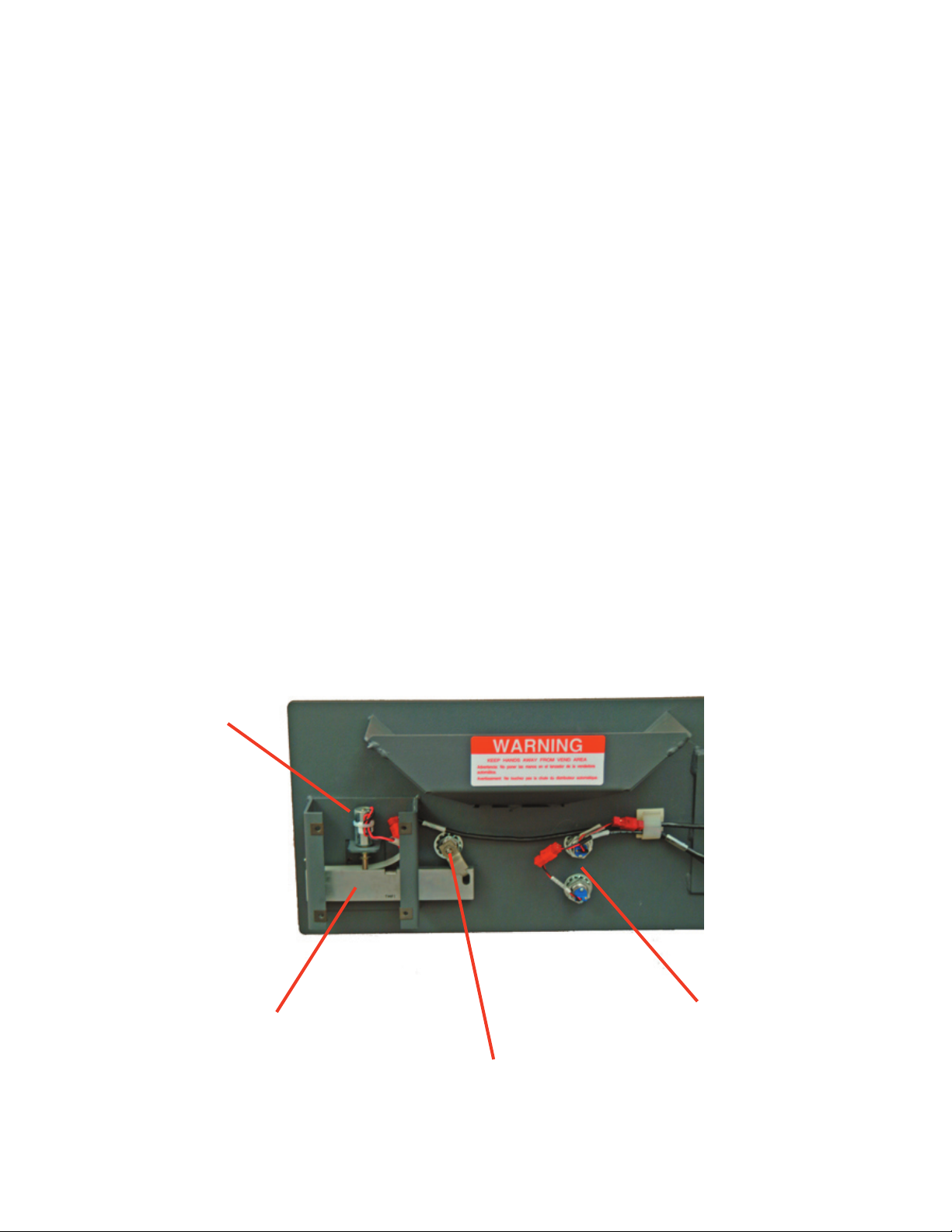
Problem Identifi cation By Component
Motors and Timing Disks
Other manuals for TACC-IIa
2
Table of contents
Other Tidel Safe manuals


Popular Safe manuals by other brands


SentrySafe
SentrySafe Master Lock Fire-Safe FPW082FS owner's manual

Dometic
Dometic XSAFE MDT400X Installation and operating manual

Rottner
Rottner Lettera Operating instruction

Hamilton
Hamilton 98RH Nighthead instruction sheet

Bunker Hill Security
Bunker Hill Security 61724 Owner's manual & safety instructions

lifelong
lifelong LLHSL08 user manual


