Tidland Maxcess Internal Element Shaft User manual

Tidland Internal Element Shaft
Installation, Operation and Maintenance Manual
EN
Ultrashaft™
MI 27L132426 1 S
TIDLAND WINDING SOLUTIONS


www.maxcessintl.com
Tidland UltrashaftTM
MI 27L132426 1 S
Page 3
IMPORTANT SAFETY INSTRUCTIONS
When using this Tidland product, basic safety precautions should always be followed to reduce the
risk of personal injury. Your company's safety instructions and procedures should always be followed.
When using this product with any other equipment or machinery, all safety requirements stipulated by
that equipment or machinery manufacturer must be followed. Compliance with local, state, and federal
safety requirements is your responsibility. No part of these or the following instructions should be
construed as conflicting with or nullifying the instructions from other sources. Be familiar with the
hazards and safety requirements in your work environment and always work safely.
Read and understand all instructions and shaft design application limits before operation.
Never use this product for a purpose or in a machine that it was not specifically designed for. See
Product Safety Data Sheet (PSDS).
Do not exceed the operation loads for this shaft as noted on its PSDS, Product Safety Data Sheet.
Follow all warnings and instructions marked on the product and on the PSDS.
Do not use fingers or other objects to deflate the shaft; Tidland recommends using the Tidland Air
Release Tool (see page 4).
Inspect the shaft for wear and/or other safety and functional deficiencies daily, before each use.
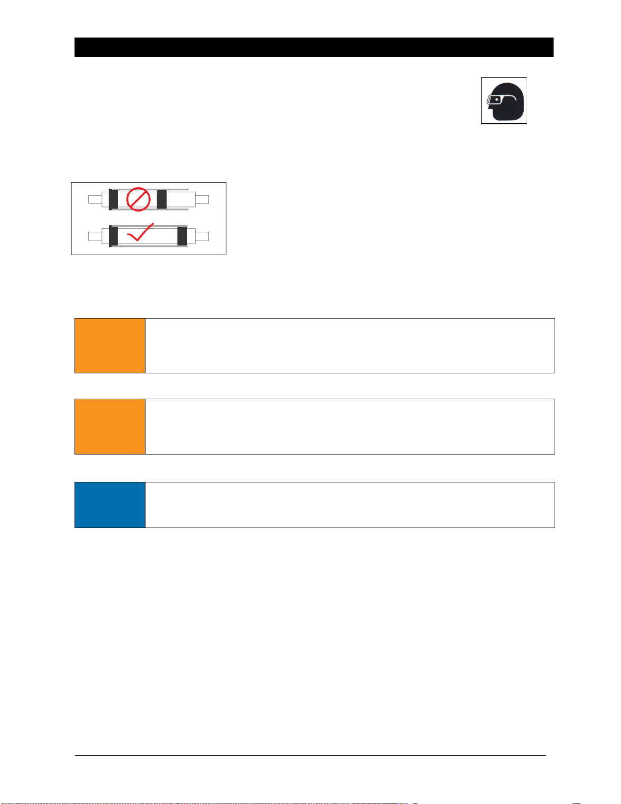
Wear safety glasses or proper eye protection when inflating or deflating or otherwise operating the air
system.
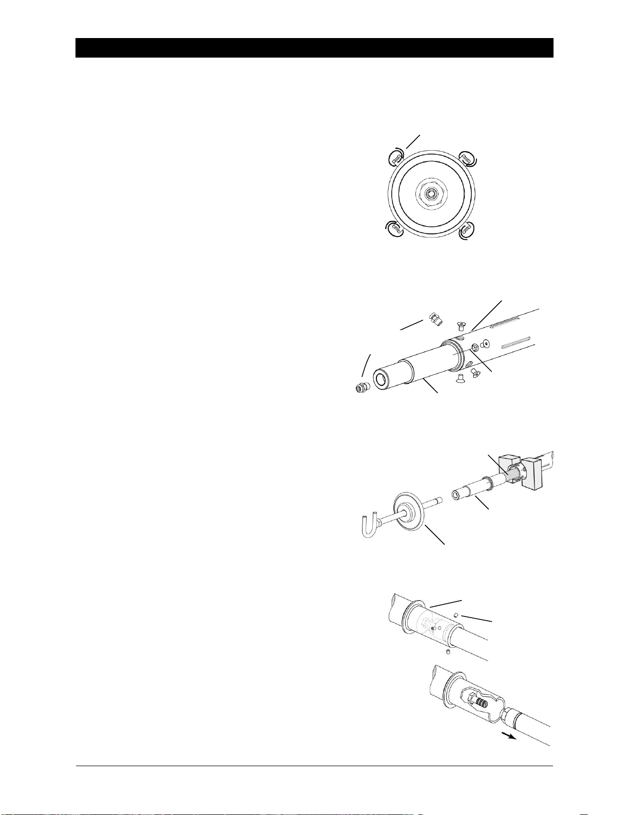
Do not remove or otherwise alter any setscrews or fastening devices prior to using this product.
Do not operate this product if any setscrews or fastening devices are missing.
Do not lift shaft manually if it is beyond your capacity. Loads over 1/3 your body weight may be
prohibitive. Consult your company safety policy.
When lifting a shaft, use proper lifting techniques, keeping back straight and lifting with the legs.
Do not carry or lift this product over wet or slippery surfaces.
Use appropriate mechanical lifting devices, such as a hoist or shaft puller, for heavier shafts.
When performing maintenance or repair procedures, do not pressurize the shaft if journal setscrews
are loose or missing.
When performing maintenance procedures, do not pressurize the shaft if the journal is missing.
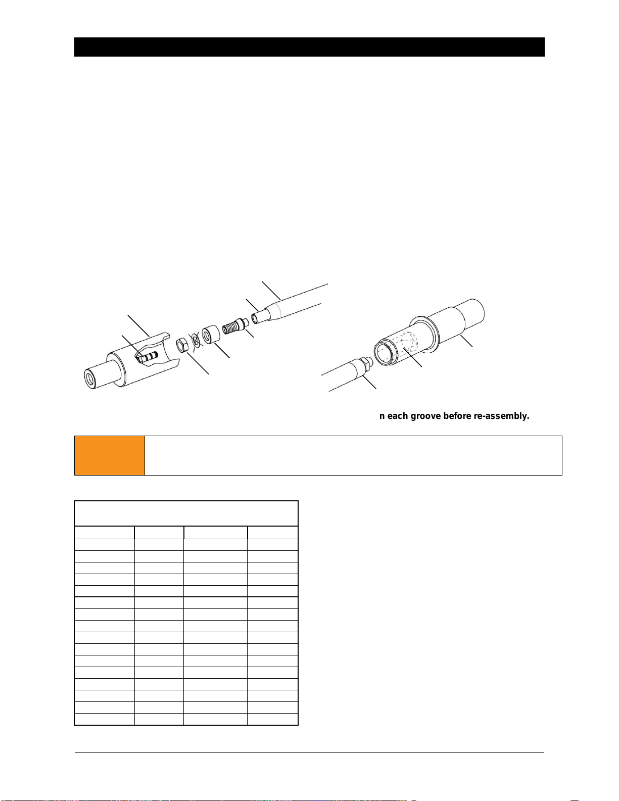
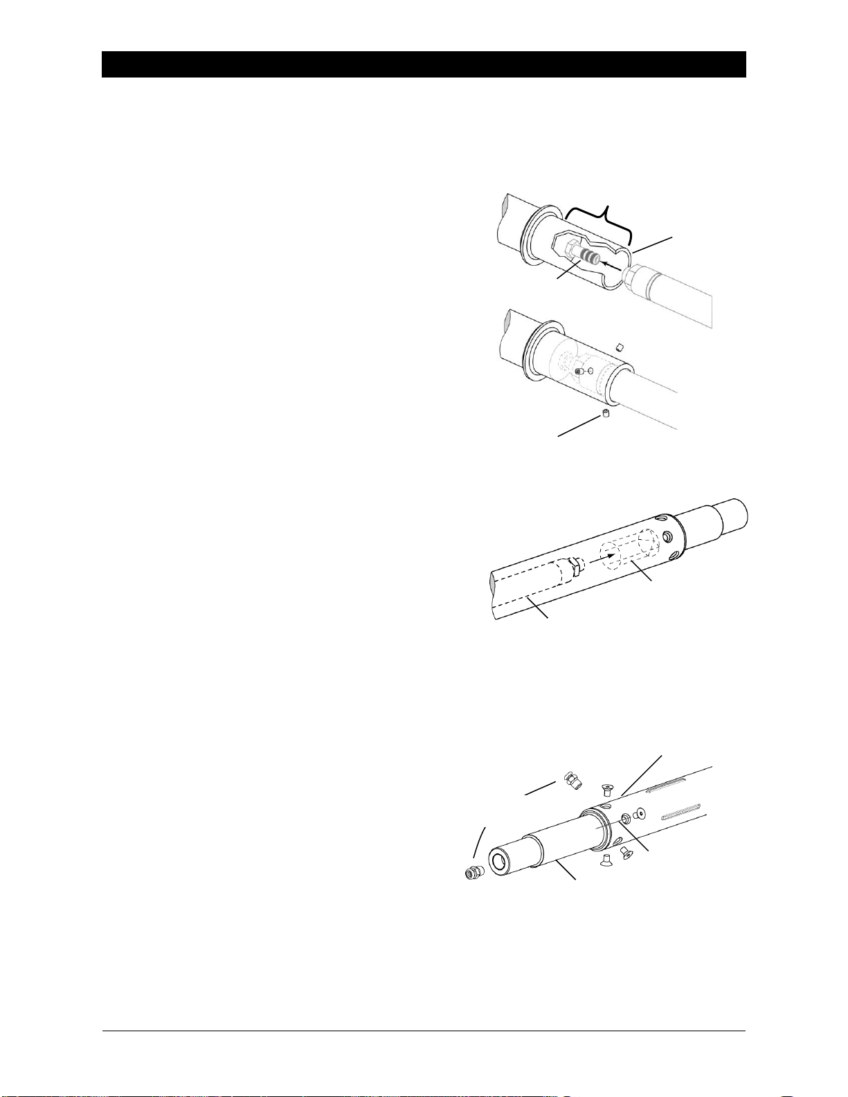
All replacement parts used on this product should be made to original Tidland specifications.
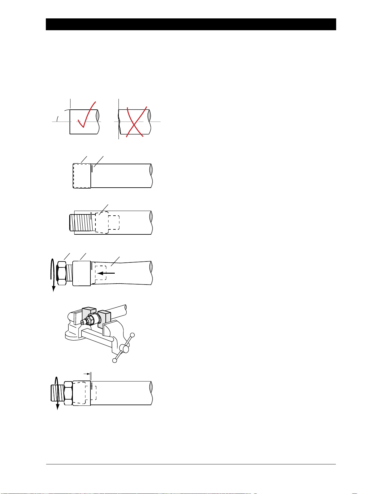
All maintenance and repair procedures performed on this product should be done to Tidland
specifications by qualified personnel.
NOTICE
If shafts with rubber air systems are stored longer than two weeks - store them
completely deflated, away from electric motors, away from direct sunlight or
florescent light, and in temperatures not exceeding 85ºF (29ºC).
When storing shafts with constant air pressure, the rubber air systems are subject to
distortion or cold flow.

www.maxcessintl.com
Tidland UltrashaftTM
MI 27L132426 1 S
Page 4
CONTENTS
Important Safety Information................................................................................................................... 3
Shaft Inspection Guidelines..................................................................................................................... 5
Caution .................................................................................................................................................... 6
Installation................................................................................................................................................ 7
Operation................................................................................................................................................. 7
To Inflate Shaft .............................................................................................................................. 7
To Deflate Shaft............................................................................................................................. 7
Maintenance............................................................................................................................................ 8
Rubber Tube Fitting Designs......................................................................................................... 8
Using the hose clamp with bulk rubber tube material............................................................. 9
Removing Rubber Tube Assembly ....................................................................................... 10
To Disassemble Rubber Tube Assembly.............................................................................. 11
Building the Rubber Tube Assembly..................................................................................... 12
Shaft Assembly Sequence with Complete Rubber Tube Assembly..................................... 13
Replacing Outer Lugs.................................................................................................................. 14
Replacing a Valve........................................................................................................................ 14
Troubleshooting..................................................................................................................................... 15
TIDLAND CUSTOMER SERVICE
+1.360.834.2345 www.maxcessintl.com
Visit the Maxcess Repair and Return Center online to review our return policies
or to submit an electronic Return Material Authorization Request.
www.maxcessintl.com/returns
RECOMMENDED TOOLS
Clean, dry, non-lubricated air supply: 80-120 psi for proper operation.
Tidland Inflation Tool (Part No. 27L128052)
Tidland Air Release Tool (Part No. 27L111630)
Pincers for removing hose clamps, if installed. See page 9.
Dow Corning Molykote®55 o-ring grease
Low-strength threadlocker (Loctite®222 or equivalent)
Thread sealant (Loctite® 545 or equivalent)
1/8” hex drive wrench
For more accessories to help with your winding processes, visit www.maxcessintl.com.

www.maxcessintl.com
Tidland UltrashaftTM
MI 27L132426 1 S
Page 5
SHAFT INSPECTION GUIDELINES
Upon Receipt
Before placing shaft in service, check visually for any damage due to shipping or mishandling. Track each
shaft individually by recording its serial number and when it went into service.
Before Each Use
Inspect the shaft daily for wear and/or other safety and functional deficiencies. Check for damaged or
missing fasteners.
Body
Visually check for any damage in fiberglass coatings: cuts greater than 1/16" (1.5 mm) deep and longer
than 1/2" (13 mm), gouges or excessive wear.
Check for cracks in metal sleeves.
Journal
Visually check for cracks or excessive wear.
If any of these problems are found, remove shaft from service and call Tidland Customer Service.
After One Year
Body –Ultrashaft™
Check for delamination of the fiberglass or cracks in the metal sleeve in and around lug slots and
fastener holes. If delamination or cracks are visible, remove shaft from service.
Body –All Shafts
Inspect lug slots or button holes for excessive wear. Check
elongation of button holes or for squaring out at the corners of the
lug slots where cracks can develop.
Journal
Check for reductions in transitional radii between journal diameter
steps. If wear is observed, check for cracks. Use magnetic-particle
or dye-penetrant, or an equivalent procedure, to detect surface
cracks. Measure diameters at those locations where journal, or
body, rides on bearings. Measure diameter at those locations where
the edges of mounted rolls ride on the shaft body, watching for
diameter reduction of 0.015" (0.4 mm) or more.
If any of these problems are found, remove shaft from service and call Tidland Customer Service.
These guidelines do not, in any way, extend or modify the Tidland Product Warranty.

www.maxcessintl.com
Tidland UltrashaftTM
MI 27L132426 1 S
Page 6
CAUTION
Wear eye protection when using tools or compressed air.
Never operate the shaft beyond the limits published in the PSDS and in this
document. Core shaft design and performance is influenced by many dynamic
variables. Load limit considerations: beam strength, deflection resistance, bearing
centers, beam section, web width, and other critical elements. For other information contact Tidland
Corporation.
When using chucks on this shaft, always locate chucks as
shown.
Improper placement of chucks will reduce life cycle
of the shaft.
Questions about installation, application or load calculations?
Call Maxcess Customer Service.
WARNING
Do not inflate rubber tube assembly outside of the shaft.
Tube fittings could disengage from assembly and become dangerous projectiles.
May result in serious injury.
WARNING
Do not inflate pad shafts unless all pads are under a core or web.
Pads can be ejected from the shaft when inflated.
May result in serious injury.
NOTICE
Removal or modification of components can affect shaft balance.
Call Tidland to confirm whether your shaft was factory-balanced
during manufacturing.

www.maxcessintl.com
Tidland UltrashaftTM
MI 27L132426 1 S
Page 7
INSTALLATION
Install shaft as required for your application.
When using chucks on this shaft, always locate chucks as
shown.
Improper placement of chucks will reduce life cycle of the
shaft.
OPERATION
Keep the Tidland Air Shaft clean and dry.
Make sure that there are no scratches or burrs on the shaft body.
Wear eye protection when using tools or compressed air.
Keep the shaft pressure above 80 psi (5.5 bar) to ensure
optimal safety and performance.
To Inflate Shaft
Do not inflate pad shafts unless all pads are under a core or web.
Pads can be ejected from the shaft when inflated.
1. Use the Tidland Inflation Tool. Push the air nozzle firmly into the valve receiver, depressing both the
valve button and the tip of the inflation tool.
2. Inflate the shaft until the line pressure air gauge indicates a minimum of 80 psi (5.5 bar). Do not
exceed the maximum air pressure of 120 psi (8.3 bar).
To Deflate Shaft
Only use the air release tool.
Do not use finger to release air.
Do not deflate while the shaft is spinning.
1. Using air release tool, push in the quick release air valve allowing the air to escape through the hole
in the center of the button.

www.maxcessintl.com
Tidland UltrashaftTM
MI 27L132426 1 S
Page 8
MAINTENANCE
Rubber Tube Fitting Designs
If your replacement rubber tube assembly looks
like this =================================>>>
Remove your old rubber tube assembly (page 10) and install
the new one, pushing the tube assembly firmly onto the o-ring
connector in the journal.
If you are using re-using your tube fittings with bulk rubber tube
material, see instructions starting on page 9.
If your replacement rubber tube assembly looks
like this =================================>>>
=== then it is directly interchangeable with older shaft designs.
There are fewer parts: rubber tube, tube fitting and hose clamp,
pictured at right.
Remove your old rubber tube assembly (page 10)and install
the new one, pushing the tube assembly firmly onto the o-ring
connector in the journal.
See page 9 for using the hose clamp design with bulk rubber
tube material.
If your replacement rubber tube assembly looks
like this =================================>>>
=== then the shaft has a hole bored in the journal to accept the
rubber tube assembly with a male o-ring connector, pictured at
right.
Remove your old rubber tube assembly (page 10) and install
the new one, pushing the tube assembly firmly into the socket
in the journal.
See page 9 for using the hose clamp design with bulk rubber
tube material.

www.maxcessintl.com
Tidland UltrashaftTM
MI 27L132426 1 S
Page 9
MAINTENANCE
Using the hose clamp with bulk rubber tube material
Removing the hose clamp
Tidland recommends the use of a pincer for safe and easy removal of the hose clamp.
Standard pincer Tidland Part No. 27L778957
Spring return pincer Tidland Part No. 27L778958
1. With the pincer, squeeze the tangs (1) on the hose clamp until you can lift the load retaining hook (2),
and then release the pincer.
2. Remove the fittings and use them again with new rubber tube material. (Remember to reinstall the tube
stiffener, if needed.)
3. To close the clamp, squeeze the tangs until you can snap the load retaining hook into place.

www.maxcessintl.com
Tidland UltrashaftTM
MI 27L132426 1 S
Page 10
MAINTENANCE
Removing Rubber Tube Assembly
Pad Shafts
1. Deflate shaft completely. Go to Step 4.
Lug Shafts
1. Inflate shaft to raise lugs.
Do not exceed 80 psi (5.5 bar).
2. Place retaining fasteners (e.g., paper clip)
in lugs to keep them in the expanded position.
This prevents the lugs from falling into the
shaft body when the rubber tube is removed.
3. Deflate shaft completely.
4. Remove valve.
5. Match mark shaft body to the valve journal flange.
6. Remove screws.
7. Lock the shaft in a vise with a round clamp to
protect the shaft body from damage.
8. Attach Tidland impact puller/slide-hammer to valve
journal end. Strike the weight against stop.
9. Remove the valve journal, pulling the rubber tube
assembly all the way out of the shaft.
Pad Shafts: The pads will fall inside the shaft body.
Remove them and reinstall after rubber tube
assembly has been replaced.
10. Loosen the three set screws that secure the rubber
tube assembly to the valve journal. Retain the set
screws for use during reassembly.
11. Pull the rubber tube assembly from the valve
journal.
CLIP TO RETAIN LUGS
VALVE JOURNAL
MATCH MARK
VALVE
(SIDE OR END)
SHAFT BODY
RUBBER TUBE ASSEMBLY
VALVE JOURNAL
IMPACT PULLER
SET SCREW
VALVE JOURNAL

www.maxcessintl.com
Tidland UltrashaftTM
MI 27L132426 1 S
Page 11
MAINTENANCE
To Disassemble Rubber Tube Assembly
This assembly consists of four parts: rubber tube element, tube fitting, end cap and jam nut. Some
assemblies also include tube stiffener.
Older assemblies may have a washer, which is no longer necessary if using Loctite 242 on tube
fitting hardware.
All fittings can be reused with new rubber tube material: if any parts are rusted or worn, Tidland
recommends replacing the entire air system.
Starting with shaft serial number 741576 (December 2011), three set screws were added to the
valve end journal to secure the rubber tube assembly. (Set screws are not illustrated here; see
page 10.)
1. Remove the nut from the valve end of the rubber tube assembly.
2. Pull the end cap off the tube.
3. Remove the tube fitting from the tube and disconnect the tube stiffener (if installed).
Note the difference in tube fittings
Valve-end fittings are bored through for air passage; non-valve fittings are solid.
Note: O-ring connector configurations vary. Make sure there is an o-ring in each groove before re-assembly.
Use this table when reassembling the rubber tube
assembly. See next page.
WARNING
Never inflate rubber tube assembly outside of the shaft.
Tube fittings could disengage from assembly and become dangerous projectiles.
Can result in serious injury.
Assembly Torque Requirements
for Standard Tube Fittings
Tube O.D.
Ft·lbs
Tube O.D.
Nm
11/16"
2-4
17 mm
3-5
3/4"
3-8
19 mm
4-11
7/8"
8-15
22 mm
11-20
1"
8-15
25 mm
11-20
1-1/8"
15-28
29 mm
20-38
1-1/4"
15-28
32 mm
20-38
1-3/8"
28-43
35 mm
38-58
1-1/2"
28-43
38 mm
38-58
1-5/8"
43-63
41 mm
58-85
1-7/8"
43-63
48 mm
58-85
2-1/8"
43-63
54 mm
58-85
2-3/8"
43-63
60 mm
58-85
3-3/8"
63-78
86 mm
85-106
4"
63-78
102 mm
85-106
4-3/8"
78-90
111 mm
106-122
4-1/2"
78-90
114 mm
106-122
VALVE JOURNAL
O-RING CONNECTOR
RUBBER TUBE
(TUBE STIFFENER)
TUBE FITTING
END CAP
NUT
RECESS (TUBE SOCKET)
NON-VALVE END ASSEMBLED THE SAME WAY
NON-VALVE JOURNAL

www.maxcessintl.com
Tidland UltrashaftTM
MI 27L132426 1 S
Page 12
MAINTENANCE
Building the Rubber Tube Assembly
When cutting rubber tube to length, it is very important to cut the ends square, without nicks or wavy
edges. Heavy tin snips work well. Any uneven cuts will not let the rubber tube seat properly in the
end cap, resulting in an unreliable assembly subject to failure under pressure.
Before assembly, clean ends of rubber tube inside and out to make sure all mold release agents or
other foreign coatings are removed. This will help prevent the rubber tube from squeezing out of the
cap when the retaining nut is tightened.
1. Cut rubber tube square at each end.
2. Install the end cap (1) on the rubber tube and mark its
position on the tube (2). Remove the end cap.
3. Insert the tube fitting (3) deep inside the rubber tube.
4. Fit the end cap (4) over the tube.
5. Squeeze the tube (5) to force the tube fitting back toward
the end.
6. Apply Loctite to the tube fitting threads and install the nut
(6). Do not tighten.
7. Secure the shaft in a round clamping fixture.
8. Tighten the nut to draw the tube fitting out until fully
seated in the end cap.
9. Tighten the nut to torque specified on page 11.
10. The end cap must be within 2 mm of the mark on the
rubber tube. Tube fitting threads should be perpendicular
to the rubber tube. If crooked, loosen the nut and repeat
the procedure.
11. Repeat the procedure for the non-valve end.
90°
2 mm
[1/16"]
2
3
6 4 5
1

www.maxcessintl.com
Tidland UltrashaftTM
MI 27L132426 1 S
Page 13
MAINTENANCE
Shaft Assembly Sequence with Complete Rubber Tube Assembly
Note:
O-ring connector configurations vary. Make sure there is an o-ring in each groove before re-assembly.
1. If replacing the o-ring connector, use a thread
sealant (liquid or pre-applied).
2. Apply o-ring grease to the o-rings on the o-ring
connector. Push the valve end tube fitting fully
over the o-ring connector in the valve journal.
You should feel a positive stop.
3. Install each of the set screws and tighten only
until they make contact with the tube cap.
4. Now torque all of the set screws to 60 in·lbs
(6 Nm).
5. Insert the non-valve end of the rubber tube
assembly into the shaft. Slide it all the way in
until it seats in the recess in the non-valve
journal.
6. Apply a light coating of o-ring grease to the fit
area of the valve journal.
7. Align the match marks on the valve journal and
the shaft body; tap the journal into place with a
rubber mallet.
8. Apply small amount of low-strength
threadlocker to threads of the journal screws.
Reinstall screws and torque to 20-25 ft·lbs
(27-34 Nm).
9. Reinstall the valve (use thread sealant unless
pre-applied) and torque to 8.8-10 ft·lbs
(12-13 Nm).
Pad Shafts: Push pads into slots from outside
the shaft. A very small amount of air in the
rubber tube will help keep the pads seated
during installation.
FIT AREA
VALVE JOURNAL
O-RING CONNECTOR
SET SCREWS
RUBBER TUBE ASSEMBLY
RECESS
VALVE JOURNAL
MATCH MARK
VALVE
(SIDE OR END)
SHAFT BODY

www.maxcessintl.com
Tidland UltrashaftTM
MI 27L132426 1 S
Page 14
MAINTENANCE
Replacing Outer Lugs
With the rubber tube removed (page 10), the outer lugs (at ends of shaft) can be replaced.
1. With the retainer clips in place, remove and replace one lug at a time. Install a retainer clip on
the new lug before proceeding to the next lug.
2. Install the rubber tube assembly (p. 13).
Note: Lugs will jam inside shaft body if clips are removed more than one at a time.
To Replace All Lugs: Tidland recommends returning the shaft for factory service.
Replacing a Valve
Shaft configurations vary. Valve may be installed in the end of the shaft or along its face.
1. Deflate the shaft. Remove all air.
2. Locate and remove the valve.
3. Apply thread sealant (according to manufacturer's directions) to the threads of the valve (unless
the sealant is pre-applied) and reinstall.
NOTE: Valves with pre-applied thread sealant are good for multiple uses. Always inspect the valve
threads for sufficient sealant; do not reuse more than six times.
4. Screw the valve into the shaft and torque to 8.8-10 ft·lbs (12-13 Nm).
RETAINER CLIPS IN LUGS
RETAINER CLIP
LUG
RUBBER TUBE ASSEMBLY
VALVE
(SIDE OR END)

www.maxcessintl.com
Tidland UltrashaftTM
MI 27L132426 1 S
Page 15
MAINTENANCE
Troubleshooting
Problem
Possible Cause
Recommended Solution
Shaft will not inflate or hold
air
Leaking rubber tube
assembly
Disassemble shaft and replace rubber tube
assembly
Valve leaking
Remove valve and apply a thread sealant*
according to manufacturer's directions.
Reinstall valve and torque to 8.8-10 ft·lbs
(12-13 Nm).
Replace valve if necessary.
Rubber tube fitting slips
off o-ring connector
O-ring connector configurations vary. Make sure
there is an o-ring in each groove of the connector.
Use o-ring grease.
Always use a thread sealant when replacing or
reinstalling o-ring connectors.
For shafts manufactured after Nov 2011, ensure
that there are three set screws installed in the
journal. See page 13.
Hose clamps not secure
Make sure the load retaining hook is locked (p. 9).
Lugs fall through slots
No tube stiffener
Call Maxcess for recommendation.
Rubber tube lies flat
when not inflated.
Cracked sleeves
Material fatigue
≤1.0" : Drill stop crack.
Call Tidland for procedure (1-360-834-2345)
>1.0" : Return sleeve for replacement.
Cores slipping
Low air pressure
Operate shaft at 80 psi minimum (5.5 bar) for
optimal performance.
Air leak
Check rubber tube assembly for leaks and replace
or repair as needed.
Remove valve and apply a thread sealant*
according to manufacturer's directions. Reinstall
valve and torque to 8.8-10 ft·lbs (12-13 Nm).
Replace valve if necessary.
Journals wear prematurely
High loads or speeds
Check PSDS specifications for your shaft
application.
Verify that journals are hardened.
Excessive shaft vibration
Shaft imbalance
Return shaft to Maxcess for dynamic balancing.
* Valves with pre-applied thread sealant (from manufacturer) can be re-used up to six times.

AMERICAS
Tel +1.360.834.2345
Fax +1.360.834.5865
sales@maxcessintl.com
www.maxcessintl.com
EUROPE, MIDDLE EAST
AND AFRICA
Tel +49.6195.7002.0
Fax +49.6195.7002.933
www.maxcess.eu
INDIA
Tel +91.22.27602633
Fax +91.22.27602634
india@maxcessintl.com
www.maxcess.in
JAPAN
Tel +81.43.421.1622
Fax +81.43.421.2895
japan@maxcessintl.com
www.maxcess.jp
© 2016 Maxcess
Table of contents
Other Tidland Industrial Equipment manuals
Popular Industrial Equipment manuals by other brands

Goiot
Goiot SLIM 6 installation instructions

Greenheck
Greenheck MAC-WK-S Installation, operation and maintenance manual

Baileigh Industrial
Baileigh Industrial MB-350 Operator's manual

Conductix-Wampfler
Conductix-Wampfler SingleFlexLine Program 0815 operating instructions

Wassermann
Wassermann Gobi-2 user manual

Vaillant
Vaillant 065 008 Instructions for installation